
Circuit Diagram
Index 1534
Gate Isolated Practical Driving Circuit
Published:2011/7/16 22:54:00 Author:nelly | Keyword: Gate Isolated, Practical
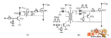
The gate isolated practical driving circuit shown in the picture applies the Pulse transformer. Picture(a) is the simple driving circuit which can control the power in the process of adjustable supply, and its duty circle is 50%. Picture(B) is the gate driving circuit which applies the PWM control, and its duty circle can be changed largely.
(a) simple driving circuit; (b)the driving circuit which has the adjustable duty circle.
Figure, gate isolated practical driving circuit (View)
View full Circuit Diagram | Comments | Reading(1446)
The Gate Isolated driving Circuit with Adjustable Duty Circle
Published:2011/7/16 23:03:00 Author:nelly | Keyword: Gate Isolated, driving, Adjustable, Duty Circle
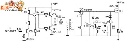
The gate isolated driving circuit shown in the picture applies the pulse transformer. This is the low-impedance output driving circuit which is composed of VT3 and VT4. In order to reduce the DC consumption, the isolated capacitor C1 is added to the circuit. VD1~VD4 selects the low drop voltage Schottky diode, VD4 and R1 are used to limit the negative peak voltage which is produced when the VF1 is limited.
Fig, The Gate Isolated driving Circuit with Adjustable Duty Circle (View)
View full Circuit Diagram | Comments | Reading(1003)
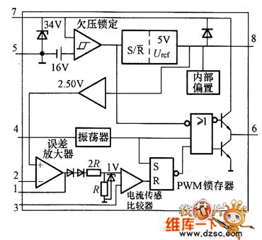
The Internal Equivalent Circuit Of UC3842 Switch Power Integrated Controller
Published:2011/7/16 23:56:00 Author:nelly | Keyword: Internal, Equivalent, Switch Power, Integrated Controller
View full Circuit Diagram | Comments | Reading(1159)
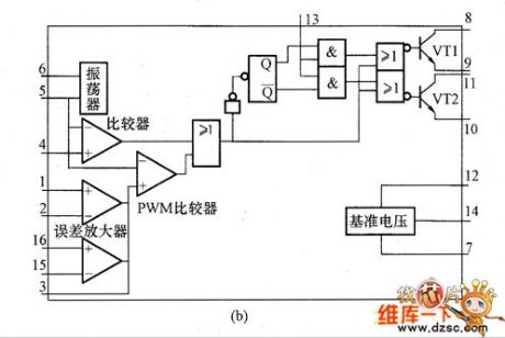
The Internal Equivalent Circuit of TL494 Switch Supply Integrated Controller
Published:2011/7/17 5:10:00 Author:nelly | Keyword: Internal Equivalent, Switch, Supply, Integrated Controller
View full Circuit Diagram | Comments | Reading(1141)
HV1205/HV2405E Internal Equivalent Circuit
Published:2011/7/17 5:14:00 Author:nelly | Keyword: Internal, Equivalent
The HV1205/HV2405E internal equivalent circuit is as shown: (View)
View full Circuit Diagram | Comments | Reading(641)
The Circuit of HIP5600 DC Output
Published:2011/7/17 5:15:00 Author:nelly | Keyword: DC Output
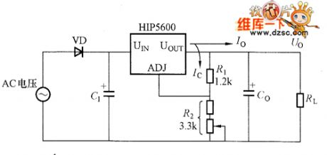
The(View)
View full Circuit Diagram | Comments | Reading(908)
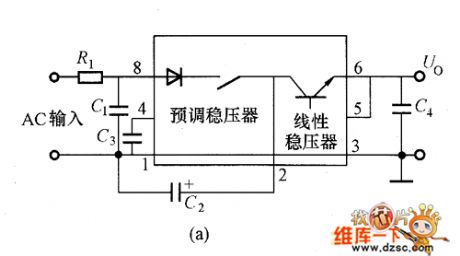
Adjustable voltage transmitting circuit
Published:2011/7/16 23:07:00 Author:nelly | Keyword: Adjustable, voltage transmitting
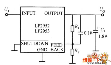
View full Circuit Diagram | Comments | Reading(554)
Unfired bricks moisture viewer 1
Published:2011/6/26 22:21:00 Author:Nicole | Keyword: Unfired brick, moisture, viewer
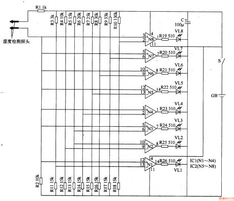
This unfired bricks moisture detector circuit is composed of humidity detector probe, operation amplifiers N1-N8(IC1, IC2), LEDs(VL1-VL8)and resistors R1-R26, it is shown in the figure 8-75.
After the power supply switch S is connected, the unfired bricks moisture detector circuit starts to work. When the humidity detector probe inserts the unfired bricks, it will produce a resistance value on the two sides of probe which changes with the water content of unfired bricks, this resistance value is amplified and processed by operation amplifiers N1-N8, the water content of unfired bricks is displayed by LEDs VL1-VL8 which is out-connected on the N1-N8 output terminal.
(View)
View full Circuit Diagram | Comments | Reading(627)
Ozone disinfector 11
Published:2011/6/30 1:28:00 Author:Nicole | Keyword: ozone disinfector

The push-pull oscillation circuit is composed of transistors V1, V2, oscillation transformer T2(W1-W3), pulse transformer T1, current limiting resistor R1, charge capacitor C3, two-way trigger diode VD5.
The half wave rectifier filter circuit is made of filter inductance coil L, rectifier diode VD1 and filter capacitors C1, C2.
The power supply is turned on, 220V AC voltage is filtered by L, it is rectifiered by VD1, it will produce about +280V voltage on the two sides of C1, it feeds to push-pull oscillation circuit.
When it is power on, V1 is turned on, due to C3's charge, two-way trigger diode VD5 is cut off.
(View)
View full Circuit Diagram | Comments | Reading(777)
Plane shaking table governor
Published:2011/7/1 1:05:00 Author:Nicole | Keyword: shaking table, governor
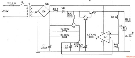
The plane shaking table governor circuit is composed of power supply input circuit and environment speed regulation control circuit, it is shown in the figure 9-159.
The power supply input circuit is made of fuse FU, power switch S, power transformer T, bridge rectifiers UR, filter capacitor C1, current limiting resistor R7 and power indication LED VL.
The speed regulation control circuit consists of resistors R1-R6, potentiometers RP1, RP2, capacitors C2, C3, diode VD, transistors V1-V3, operation amplifier IC and motor M.
(View)
View full Circuit Diagram | Comments | Reading(882)
Medical treat ventilator controller
Published:2011/7/1 1:21:00 Author:Nicole | Keyword: ventilator, controller
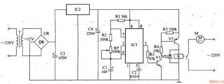
The medical treat ventilator controller circuit is composed of astable oscillator, control circuit and power supply circuit, it is shown in the figure 9-155.
The astable oscillator circuit is made of resistors R1, R2, potentiometer RP, capacitors C1, C2 and time base integrated circuit IC1.
The control circuit consists of resistors R3-R5, transistors V1, V2, diode VD and relay K.
The power supply circuit is composed of power transformer T, bridge rectifier UR rectifier, filter capacitors C3, C4 and there terminals steady voltage integrated circuit IC2.
(View)
View full Circuit Diagram | Comments | Reading(2845)
Electronic snore-ceasing equipment 2
Published:2011/6/27 3:57:00 Author:Nicole | Keyword: Electronic snore-ceasing equipment
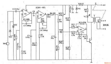
The snoring detection circuit is made of microphone BM, limiter diodes VD1, VD2, coupling capacitor C1 and selection frequency component R1, C2.
The preposition amplifier circuit consists of operation amplifier integrated circuit IC(N1-N3)internal operation amplifier N1, N2 and peripheral device.
The pulse generation circuit(belong to low frequency self-exciting oscillator)is composed of IC internal operation amplifier N3 and peripheral resistor capacitor components.
The pulse change circuit is made of switch tube V, boost transformer T and potentiometer RM.
(View)
View full Circuit Diagram | Comments | Reading(695)
Thermometer meter slinger 1
Published:2011/6/29 20:06:00 Author:Nicole | Keyword: thermometer, meter slinger
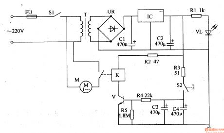
The thermometer meter slinger circuit is composed of power supply circuit and meter slinger timing control circuit, it is shown in the figure 9-134.
The power supply circuit is made of fuse FU, power supply switch S1, power transformer T, bridge rectifiers UR, filter capacitors C1, C2, there terminals steady voltage integrated circuit IC, current limiting resistor R1 and power supply indication LED VL.
After power supply switch S1 is turned on, 220V AC voltage is stepped down by T, it is rectified by UR, it is filtered by C1, it is stabilized by IC, it provides the timing control circuit with +12V voltage. +12V voltage is current limited and stepped down by R1, then it lights VL.
(View)
View full Circuit Diagram | Comments | Reading(775)
Motor protector 16
Published:2011/6/27 22:10:00 Author:Nicole | Keyword: Motor, protector
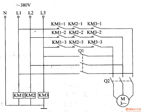
This motor protector circuit is made of AC contactor KM1, it is shown in the figure 8-52.
When 380V AC power voltage is normal, the AC contacts are all turned on, if knife switch Q2 is closed, then motor M runs.
Due to lightning or other reasons, the 380V AC voltage is lack-phase, one of KM1-KM3 AC contacts will not pull in or power failure and release, the motor M's power supply cirucit is cut off, then it protects the motor M. For example, when L2 phase line voltage disappears, AC contact KM2 releases, the normally open contact KM2-1-KM2-3 turns off.
(View)
View full Circuit Diagram | Comments | Reading(611)
Motor protector 15
Published:2011/6/27 21:53:00 Author:Nicole | Keyword: Motor, protector
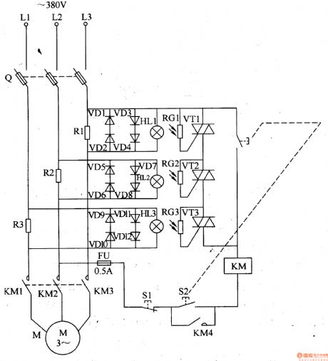
This motor protector circuit is current sampling detection circuit and optical control protection circuit, it is shown in the figure 8-51.
The current sampling detection circuit is made of sampling resistors R1-R3.
The optical control protection circuit consists of protection diodes VD1-VD12, small bulbs HL1-HL3, photosensitive resistors RG1-RG3 and thyristors VT1-VT3.
Q is fuse type knife switch, FU is fuse, S1 is stop button, S2 is starter button, KM is AC contactor.
When starter button S2 is pressed, KM pulls in, the normally open contact is turned on, motor M starts running, when the three-phase AC supply is normal, the both sides of sampling resistors R1-R3's voltage all drop to 1V.
(View)
View full Circuit Diagram | Comments | Reading(590)
Negative oxygen ion generator 6
Published:2011/6/28 2:01:00 Author:Nicole | Keyword: oxygen ion, generator
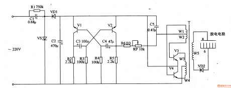
This negative oxygen ion generator circuit is composed of power supply circuit, multivibrator and high voltage circuit, it is shown in the figure 9-118.
The power supply circuit is made of capacitors C1, C2, resistor R1, steady voltage diode VS and rectifier diode VD1.
The multivibrator consists of transistors V1, V2, resistors R2-R5 and capacitors C3, C4.
The high voltage circuit is composed of capacitor C5, resistor R6, potentiometer RP, transistors V3, V4, high voltage transformer T, high voltage rectifier diode VD2 and high voltage discharge electrodes a, b.
(View)
View full Circuit Diagram | Comments | Reading(1541)
Negative oxygen ion generator 5
Published:2011/6/28 1:51:00 Author:Nicole | Keyword: oxygen ion, generator
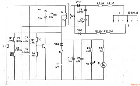
This negative oxygen ion generator circuit is composed of power supply circuit, multivibrator, high voltage discharge circuit and fan circuit, it is shown in the figure 9-117.
The power supply circuit is made of power supply switch S, battery GB, diode VD1, capacitors C1, C2, resistor R1 and LED VL.
The multivibrator consists of transistors V1, V2, resistors R3-R6, capacitors C3-C7, steady voltage diodes VS1, VS2 and windings W1, W2 of pulse transformer T.
The high voltage discharge circuit is composed of twice winding(W3) of T, diodes VD2, VD3, capacitors C8, C9, resistors R7-R10 and discharge electrode.
(View)
View full Circuit Diagram | Comments | Reading(2672)
Negative oxygen ion generator 4
Published:2011/6/28 1:33:00 Author:Nicole | Keyword: oxygen ion, generator
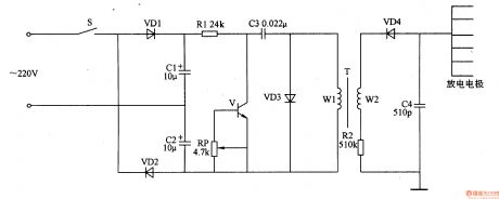
This negative oxygen ion generator circuit is composed of full wave dual voltage rectifier circuit, pulse oscillation circuit and negative high voltage generation circuit, it is shown in the figure 9-116.
The dual voltage rectifier circuit is made of diodes VD1, VD2, and capacitors C1, C2.
The pulse oscillation circuit consists of transistor V, resistor R1, potentiometer RP, capacitor C3, diode VD3 and once winding of boost transformer T.
The negative high voltage generation circuit is composed of twice winding of T, high voltage silicon rectifier stack VD4, resistor R2 and capacitor C4.
(View)
View full Circuit Diagram | Comments | Reading(5805)
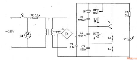
Medical ultrasonic atomizer 2
Published:2011/6/29 22:40:00 Author:Nicole | Keyword: ultrasonic atomizer
The medical ultrasonic atomizer circuit is composed of power supply circuit, atomization amount liquid level detection control circuit, ultrasonic oscillator and fan motor M, it is shown in the figure 9-111.
The power supply circuit is made of timer Q, fuses FU1, FU2, power transformer T, bridge rectifiers UR, resistors R1, R2, LED VL and filter capacitor C1.
The atomization amount/liquid level detection control circuit consists of resistor R3, potentiometers RP1, RP2, magnetic control water level switch SA(it is composed of float with magnetic ring and reed switch)and capacitor C2.
(View)
View full Circuit Diagram | Comments | Reading(4671)
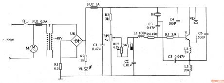
Medical ultrasonic atomizer 1
Published:2011/6/29 22:27:00 Author:Nicole | Keyword: ultrasonic atomizer
The medical ultrasonic atomizer circuit is composed of power supply circuit, ultrasonic oscillator and atomizer circuit, it is shown in the figure 9-110.
The power supply circuit is made of timer Q, fuse FU, current transformer T, bridge rectifiers UR, current limiting resistor R2, power supply indication LED VL and filter capacitor C4.
The ultrasonic oscillator circuit consists of transistor V, resistor R1, potentiometer RP, thermal resistor RT, capacitorS C2, C3 and inductors L1, L2.
The atomizer circuit is composed of piezoelectric ultrasonic transducer B, capacitor C1 and fan motor M.
(View)
View full Circuit Diagram | Comments | Reading(8071)
| Pages:1534/2234 At 2015211522152315241525152615271528152915301531153215331534153515361537153815391540Under 20 |
Circuit Categories
power supply circuit
Amplifier Circuit
Basic Circuit
LED and Light Circuit
Sensor Circuit
Signal Processing
Electrical Equipment Circuit
Control Circuit
Remote Control Circuit
A/D-D/A Converter Circuit
Audio Circuit
Measuring and Test Circuit
Communication Circuit
Computer-Related Circuit
555 Circuit
Automotive Circuit
Repairing Circuit