
Circuit Diagram
Index 1524
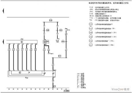
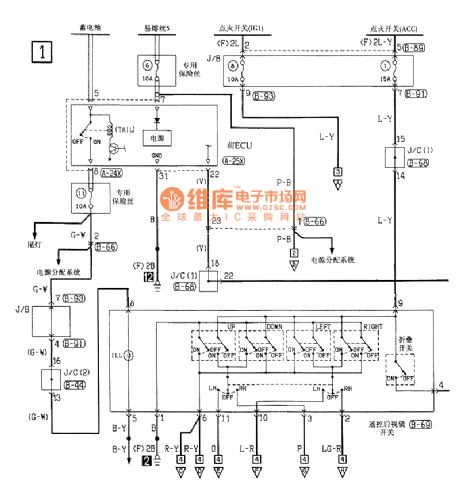
Altima A33-EC power steering pressure switch circuit
Published:2011/7/17 2:11:00 Author:Fiona | Keyword: power steering pressure switch
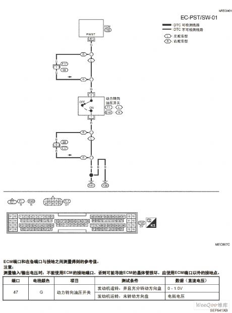
Altima A33-EC power steering pressure switch circuit is shown as above:
(View)
View full Circuit Diagram | Comments | Reading(962)
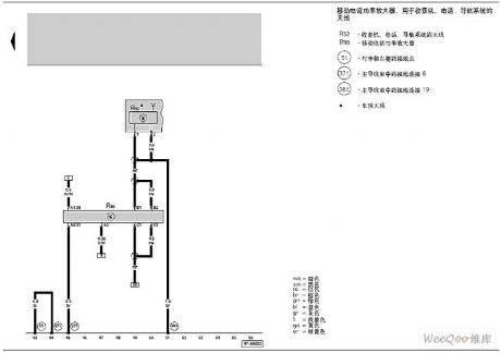
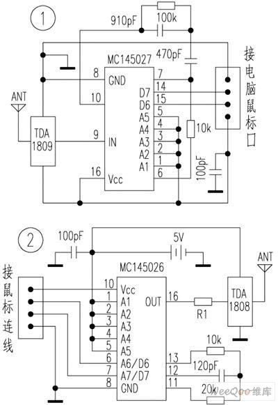
Audi A6-Mobile phone adapter device circuit Figure 2
Published:2011/7/15 2:33:00 Author:Fiona | Keyword: Mobile phone adapter device
View full Circuit Diagram | Comments | Reading(437)
Audi A6-Mobile phone adapter device circuit Figure 1
Published:2011/7/15 2:34:00 Author:Fiona | Keyword: Mobile phone adapter device
View full Circuit Diagram | Comments | Reading(422)
Audi A6-Mobile phone adapter device circuit
Published:2011/7/15 2:34:00 Author:Fiona | Keyword: Mobile phone adapter device
View full Circuit Diagram | Comments | Reading(523)
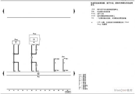
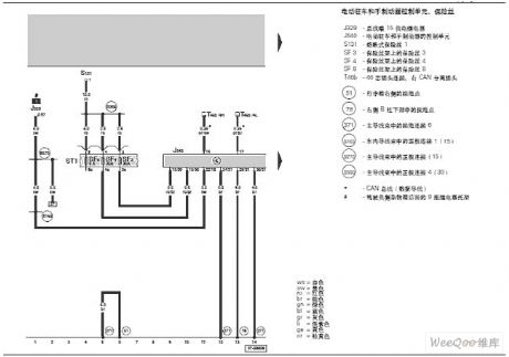
Audi A6-Electronic parking and hand brake circuit Figure 2
Published:2011/7/15 2:36:00 Author:Fiona | Keyword: Electronic parking, hand brake
View full Circuit Diagram | Comments | Reading(1372)
Audi A6-Electronic parking and hand brake circuit Figure 1
Published:2011/7/15 2:37:00 Author:Fiona | Keyword: Electronic parking, hand brake
View full Circuit Diagram | Comments | Reading(2353)
High-power electronics insect expelling device circuit
Published:2011/7/15 2:40:00 Author:Fiona | Keyword: electronics insect expelling device
High-power electronics insect expelling device circuit is shown sa above:
(View)
View full Circuit Diagram | Comments | Reading(504)
48 V input 12 V output DC step-down voltage circuit
Published:2011/7/16 4:23:00 Author:Fiona | Keyword: DC step-down voltage
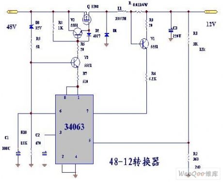
48 V input 12 V output DC step-down voltage circuit is shown as above:
(View)
View full Circuit Diagram | Comments | Reading(2031)
Crystal frequency stabilization FM circuit
Published:2011/7/16 6:05:00 Author:Fiona | Keyword: frequency stabilization, FM
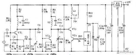
Crystal frequency stabilization FM circuit is shown as above: (View)
View full Circuit Diagram | Comments | Reading(821)
The circuit using NPN tube and voltage-regulator tube to realize the control of constant voltage and constant current
Published:2011/7/16 6:16:00 Author:Fiona | Keyword: NPN tube and voltage-regulator tube, the control of constant voltage and constant current
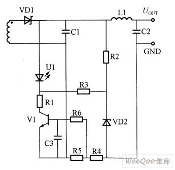

The circuit using NPN tube and voltage-regulator tube to realize the control of constant voltage and constant current is shown as above:
(View)
View full Circuit Diagram | Comments | Reading(916)
control of constant voltage and constant current circuit composed of PNP tube and voltage-regulator tube
Published:2011/7/16 6:19:00 Author:Fiona | Keyword: control of constant voltage and constant, PNP tube and voltage-regulator tube
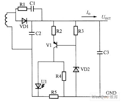
control of constant voltage and constant current circuit composed of PNP tube and voltage-regulator tube is shown as above:
(View)
View full Circuit Diagram | Comments | Reading(1072)
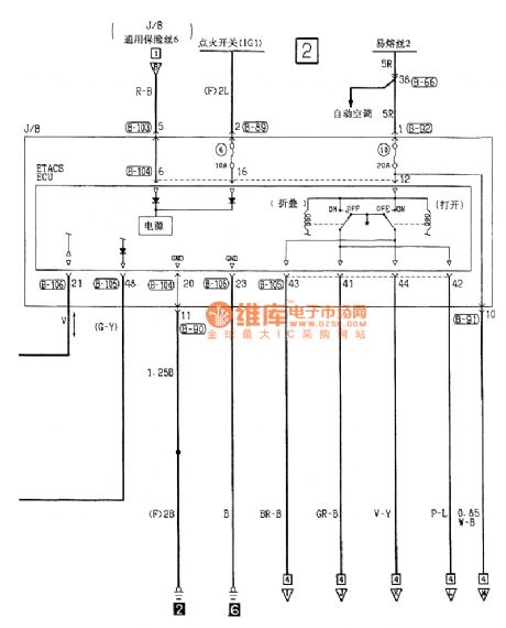
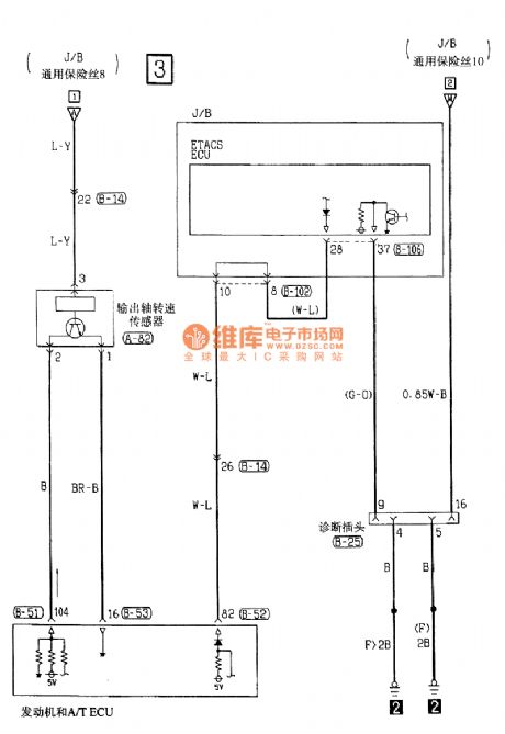
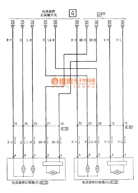
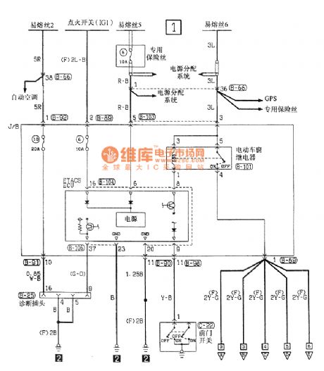
Southeast Soveran electric folding remote control mirror electric system circuit
Published:2011/7/12 8:27:00 Author:John | Keyword: electric folding remote control mirror, electric system
View full Circuit Diagram | Comments | Reading(967)
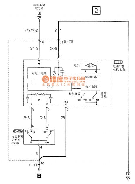
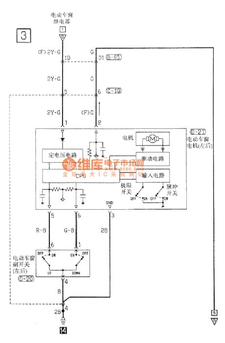
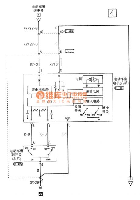
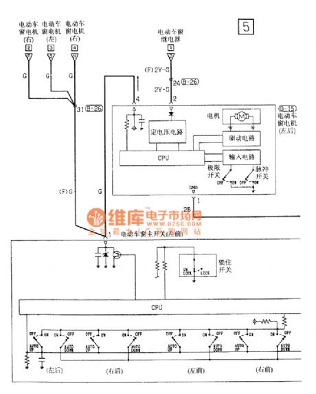
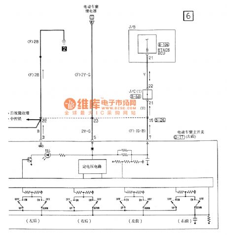
Southeast Soveran power window electrical system circuit
Published:2011/7/12 8:30:00 Author:John | Keyword: power window, electrical system
View full Circuit Diagram | Comments | Reading(974)
Control of constant voltage and constant current circuit composed of current amplifier
Published:2011/7/18 2:51:00 Author:Fiona | Keyword: current amplifier, constant voltage and constant current
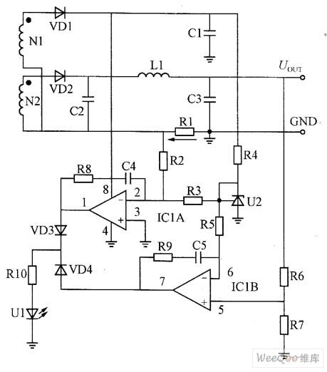
Constantvoltage circuit working principle:U2,ICIB,R6,R7,VD4,R10 and U1 form the voltage control loop. U2 (TL431) is a precision voltage regulator, cathode K and the control electrode R directly shorts circuit to form the precision 2.5V reference voltage. R4 is U2's current-limiting resistor.2.5V reference voltage is sent to the inverting input ICIB (6 pin) by the resistor R5; and non-inverting input (5 pin) is set by R6, R7's partial pressure ratio.If the output voltage rises,the UR7's voltage rises too,this voltage compares to the negative terminal 2.5V reference voltage,7-pin outputs error signal,and then becomes into a current signal through the VD4 and RIO,inflows the optocoupler's LED, and then through the feedback control and network control to make the primary side PWM output duty cycle,so that the output voltage is in the constant state.
(View)
View full Circuit Diagram | Comments | Reading(3038)
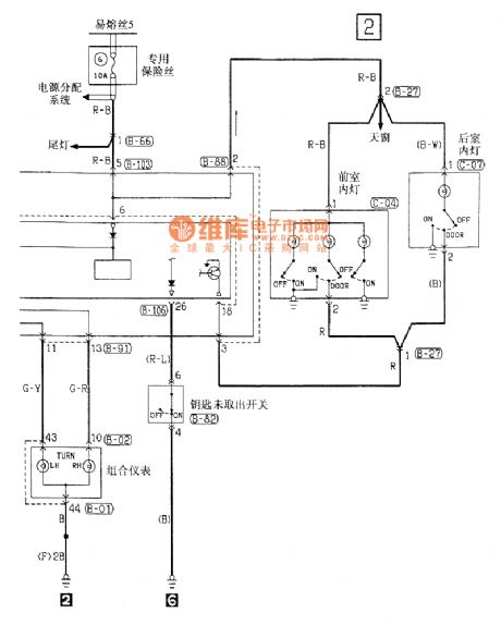
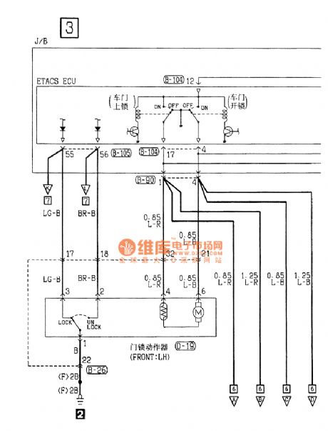
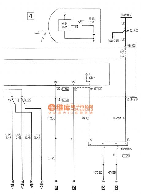
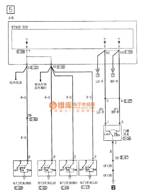
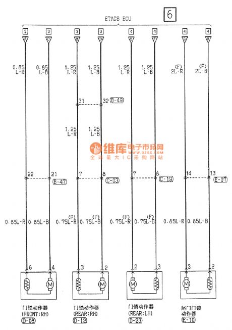
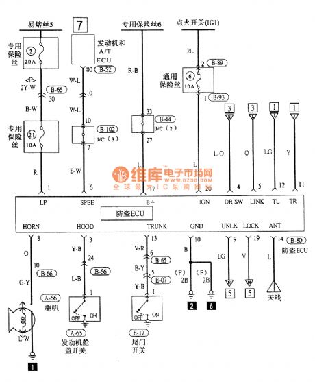
Southeast Soveran central locking and alarming electrical system circuit
Published:2011/7/12 8:34:00 Author:John | Keyword: central locking, alarming, electrical system
View full Circuit Diagram | Comments | Reading(867)
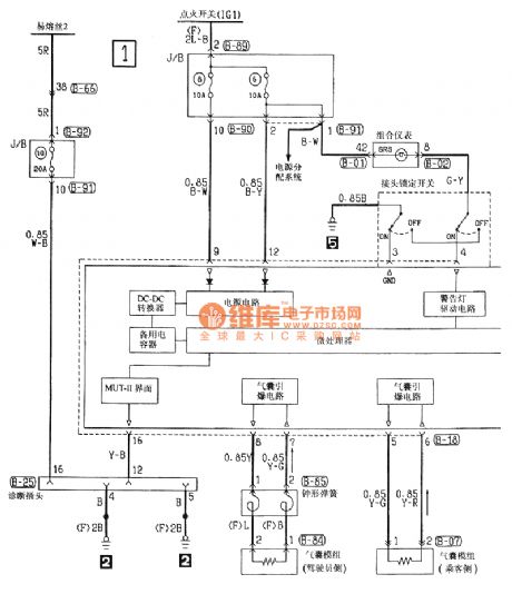
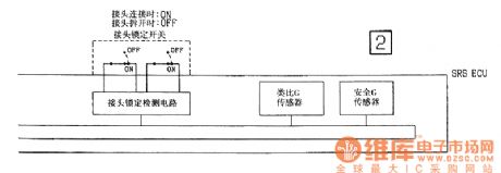
Southeast Soveran airbag electrical system circuit
Published:2011/7/12 8:36:00 Author:John | Keyword: airbag, electrical system
View full Circuit Diagram | Comments | Reading(1042)
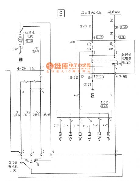
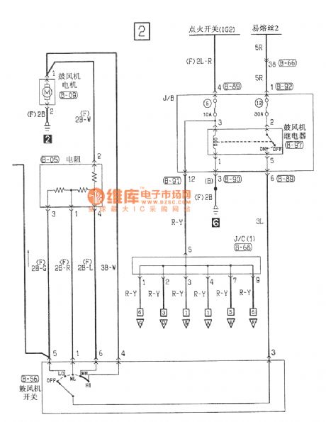
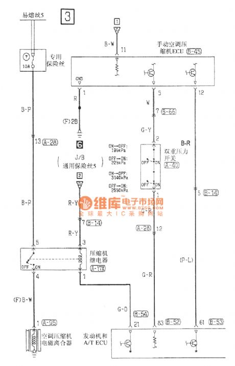
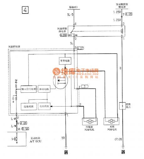
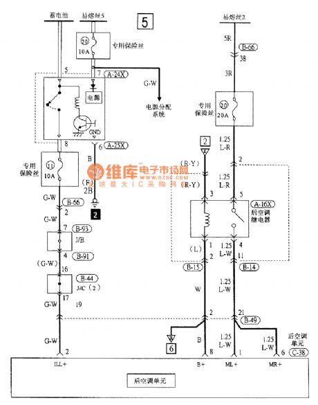
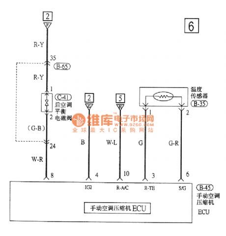
Southeast Soveran manual air-conditioning electrical system circuit
Published:2011/7/12 8:39:00 Author:John | Keyword: manual air-conditioning, electrical system
View full Circuit Diagram | Comments | Reading(904)
A simple without transformer converter circuit
Published:2011/7/16 7:24:00 Author:Fiona | Keyword: without transformer, converter
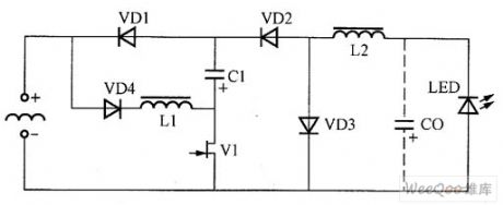
A simple without transformer converter circuit is shown as above.Input rise and fallvoltage level circuit is composed of VD4,L1,C1,VD1 in series,the output reduction voltage level is composed of the L2,VD3,VD2,CO.The two levels of conversion level common using power is decided by MOSFI tube's V1.Input rise and fallvoltage level circuit works in Intermittent mode(DCM); when the output level works,the working is in continuous mode (CCM).
(View)
View full Circuit Diagram | Comments | Reading(766)
1000W LED adjustable output voltage driver power circuit
Published:2011/7/16 8:04:00 Author:Fiona | Keyword: adjustable output voltage, driver

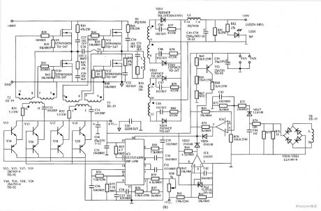
Figure (a) is 1000W LED adjustable output voltage driver PFC and auxiliary power supply circuit,including input rectifier filter circuit,EMI suppression circuit, power factor correction circuit and auxiliary power supply circuit; Figure (b) is l000W LED adjustable output voltage drive full-bridge converter circuit, including full-bridge driver circuit,full-bridge converter circuit,the output rectifier filter circuit,PWM control circuit and various protection circuits.
(View)
View full Circuit Diagram | Comments | Reading(4929)
Shanghai Buick engine control part circuit
Published:2011/7/16 8:06:00 Author:Fiona | Keyword: engine control

Shanghai Buick engine control part circuit is shown as above:
(View)
View full Circuit Diagram | Comments | Reading(405)
| Pages:1524/2234 At 2015211522152315241525152615271528152915301531153215331534153515361537153815391540Under 20 |
Circuit Categories
power supply circuit
Amplifier Circuit
Basic Circuit
LED and Light Circuit
Sensor Circuit
Signal Processing
Electrical Equipment Circuit
Control Circuit
Remote Control Circuit
A/D-D/A Converter Circuit
Audio Circuit
Measuring and Test Circuit
Communication Circuit
Computer-Related Circuit
555 Circuit
Automotive Circuit
Repairing Circuit