
Circuit Diagram
Index 1523
Two-phase servo drive circuit
Published:2011/7/12 10:22:00 Author:John | Keyword: Two-phase servo drive
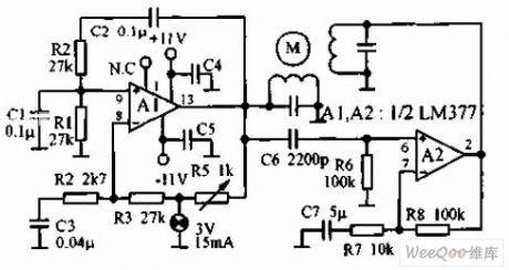
Two-phase servo drive circuit is as shown, which utilizes two components of an integrated power amplifier LM377. These two components, respectively, produce power of 3W to drive small 60Hz two-phase servo motor. The motor winding is of 8Ω, which is tuned to 60Hz with the shunt capacitor. The light bulb is used in steady ring circuit.
(View)
View full Circuit Diagram | Comments | Reading(706)
Servo position remote control circuit
Published:2011/7/12 10:28:00 Author:John | Keyword: remote control, Servo
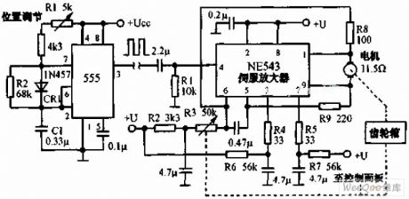
Servo position remote control circuit is shown. The system includes three components, which are named the square wave generator, servo amplifier and servo. Appropriate square wave is added to input end of the amplifier through wires. The position’s regulation potentiometer of the square wave generator can decide the servo motor’s position.
(View)
View full Circuit Diagram | Comments | Reading(629)
Small capacitance and long duration timer circuit
Published:2011/7/12 9:46:00 Author:John | Keyword: timer
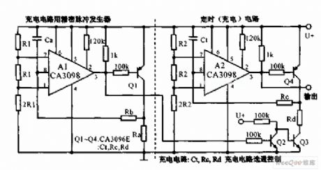
Small capacitance and long duration timer circuit is as shown. When a few hours of delay is needed, two dual-input precision level detectors CA3098 can be used. It is not necessary to use the high-capacity and low-leakage capacitor. If Rc = 22MΩ, RD = 100KΩ, 4 hours’ delay timer can be achieved as long as the CTK is 16μF.
(View)
View full Circuit Diagram | Comments | Reading(1301)
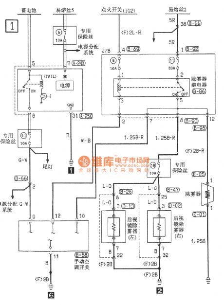
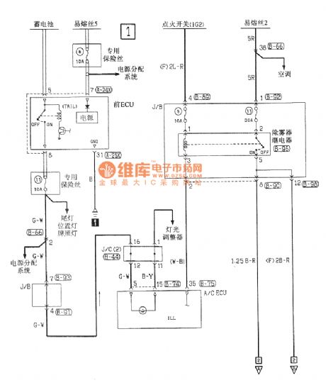
Southeast Soveran manual air conditioning demisting electrical system circuit
Published:2011/7/12 8:40:00 Author:John | Keyword: manual air conditioning, demisting electrical system
View full Circuit Diagram | Comments | Reading(818)
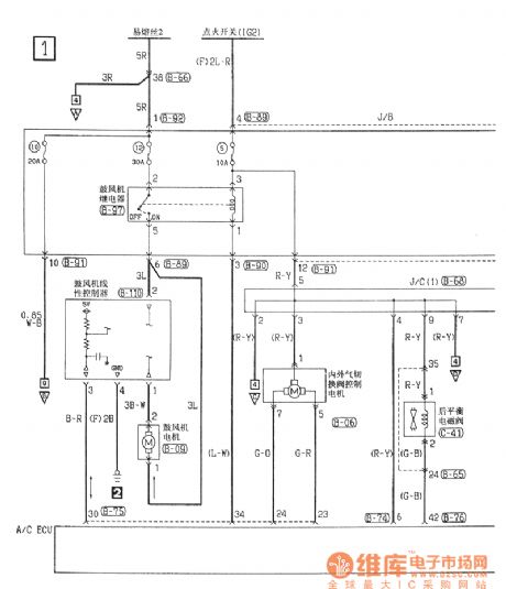
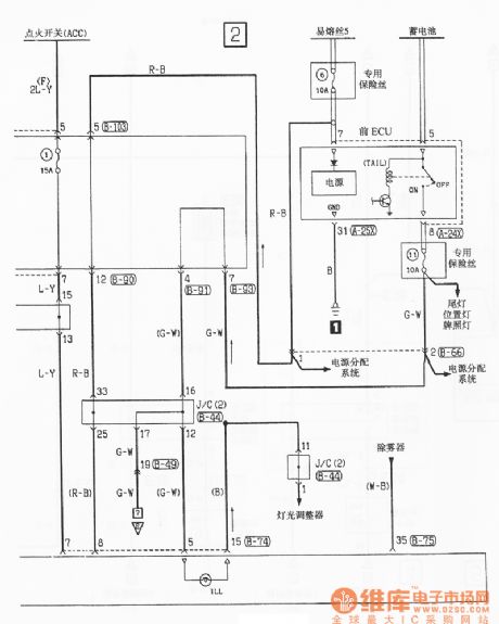
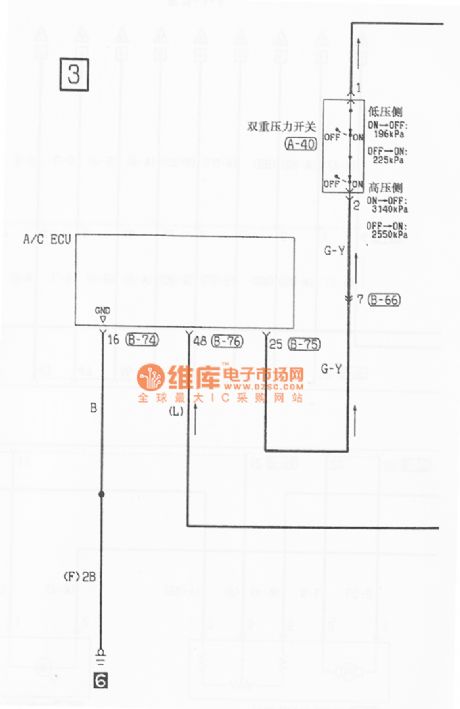
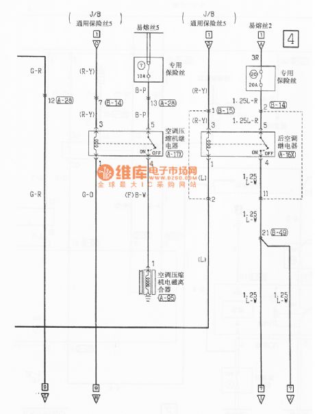
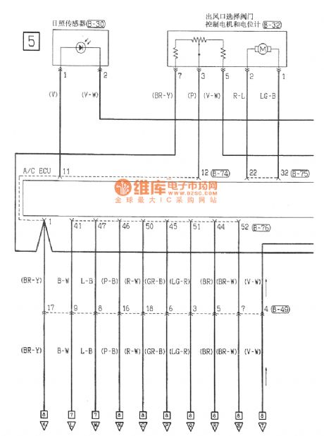
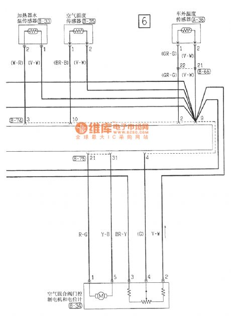
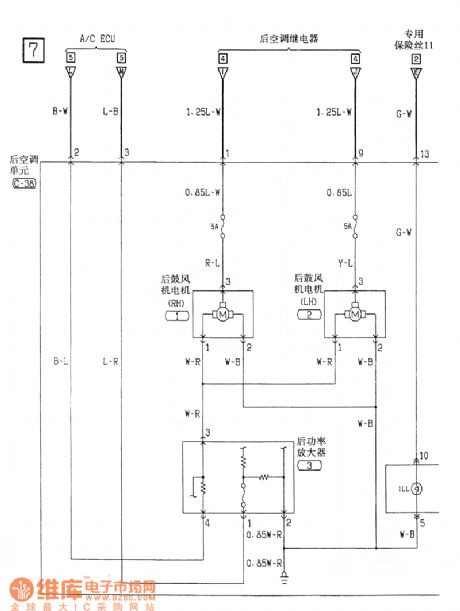
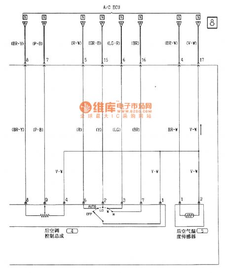
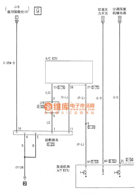
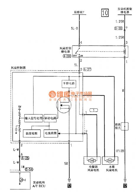
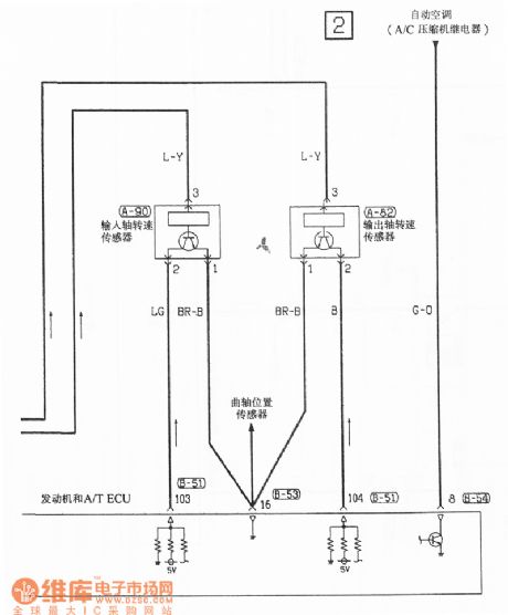
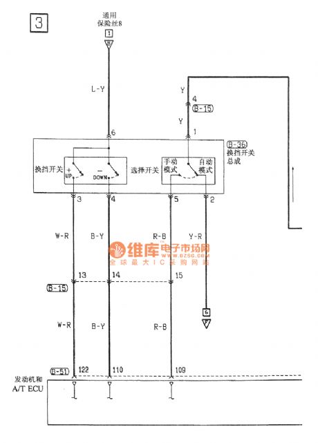
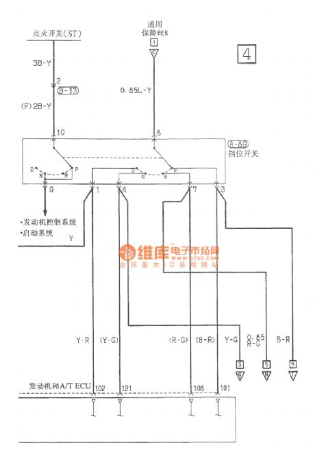
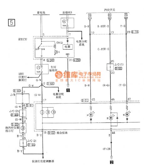
Southeast Soveran automatic air conditioning electrical system circuit
Published:2011/7/12 9:15:00 Author:John | Keyword: automatic air conditioning, electrical system
View full Circuit Diagram | Comments | Reading(933)
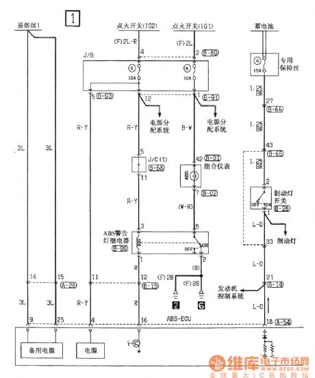
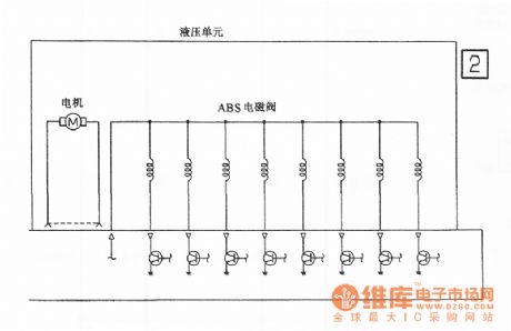
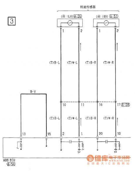
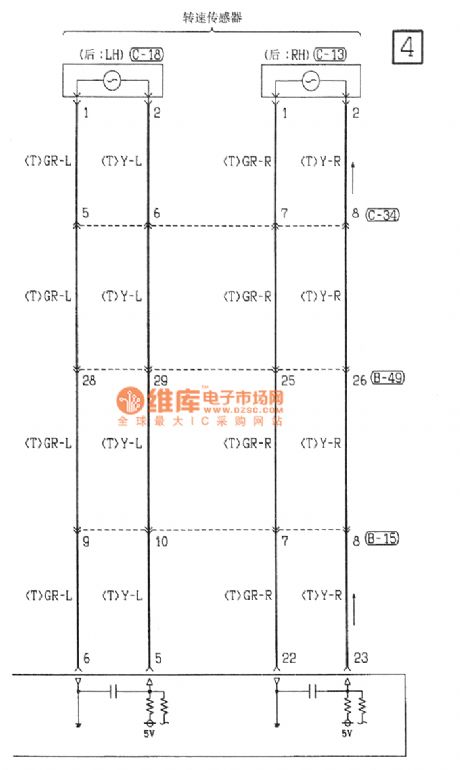
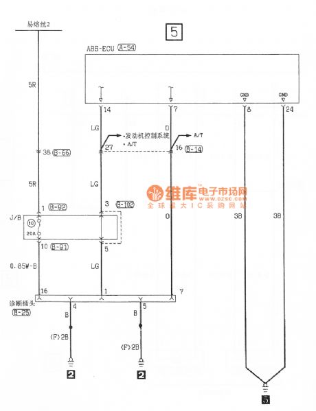
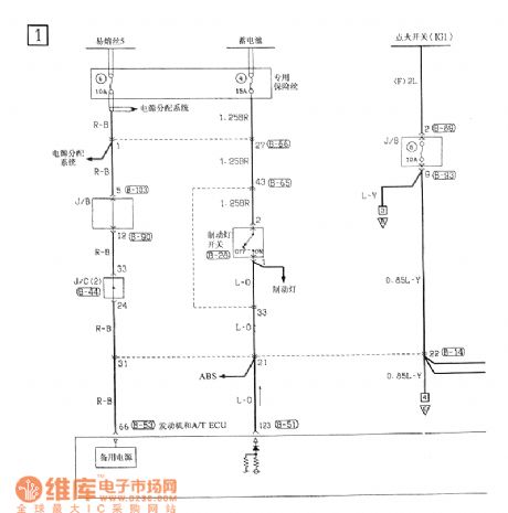
Southeast Soveran ABS chassis circuit
Published:2011/7/12 9:18:00 Author:John | Keyword: ABS chassis
View full Circuit Diagram | Comments | Reading(878)
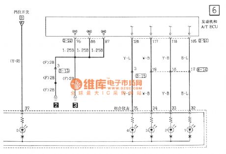
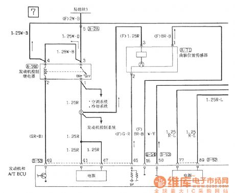
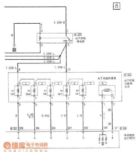
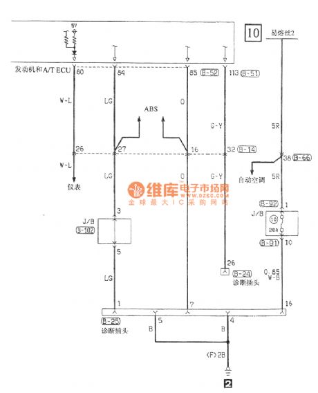
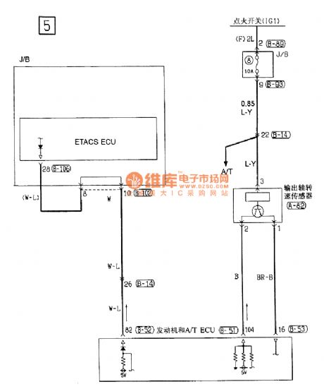
Southeast Soveran INVES-II 4A / T chassis circuit
Published:2011/7/12 9:23:00 Author:John | Keyword: chassis
View full Circuit Diagram | Comments | Reading(769)
Southeast Soveran charging system circuit
Published:2011/7/12 9:37:00 Author:John | Keyword: charging system
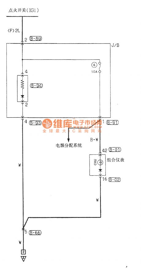
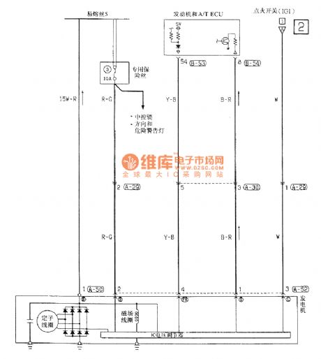
View full Circuit Diagram | Comments | Reading(824)
oil crop roaster controller
Published:2011/7/16 19:46:00 Author:chopper | Keyword: roaster controller
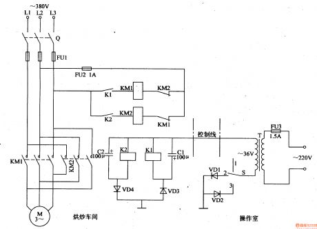
This example describes the oil crop roaster controller, which can achieve the long-distance control to roasted devices. The principle of circuit The oil crop roaster controller circuit is actual a motor single-track and remote positive and negative rotary-controlling circuit,which is shown in Figure 4-130.
Fuse FU3,power transformer T,the control switch S and diodes VD1,VD2 are installed in controller circuit of the operating room; motor M,knife switch Q, fuses FU1,FU2,AC contactors KM1,KM2,relays K1,K2,capacitors C1,C2 and diodes VD3,VD4 are installed in the blender of roaster drive circuit of roasting truck; the controller and the blender of roaster drive circuit are connected through a control line.
(View)
View full Circuit Diagram | Comments | Reading(698)
three-phase motor phase-shifting starter
Published:2011/7/15 21:05:00 Author:chopper | Keyword: phase-shifting starter
Three-phase AC motor usually requires to install phase-shifting capacitor to start when it uses 220V voltage.As for the three-phase AC motor whose power is 2-3KW,it needs the phase-shifting capacitor whose capacity is over 2OOμF,and the capacitor size is bigger,the price is higher.This example describes the three-phase motor phase-shifting starter,which can replace the phase-shifting capacitor,and make the three-phase AC motor in 220V AC supply voltage easier to start, and more reliable than phase-shifting capacitor.
(View)
View full Circuit Diagram | Comments | Reading(748)
substitutive motor centrifugal switch circuit(2)
Published:2011/7/16 20:04:00 Author:chopper | Keyword: centrifugal switch
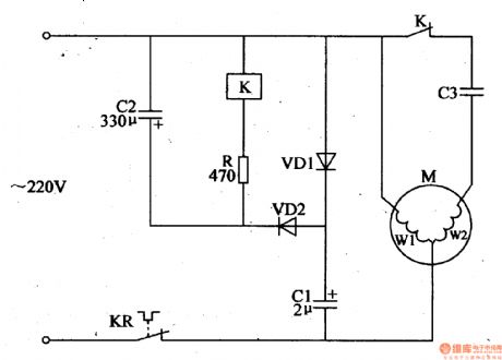
The principle of circuit The substitutive motor centrifugal switch circuit is formed by the capacitors C1,C2,resistor R,the relay K, the diodes VD1,VD2 and thermal relay KR,which is shown in Figure 4-126. After the power supply is turned on,one of the 220V AC voltage is added to the main winding of motor M(W1) through thermal relay KR,and the other is added to the starter circuit composed of the capacitor C3 and secondary winding (W2) of motor Mthrough normal closed contact of relay K,and then the motor M will start.
(View)
View full Circuit Diagram | Comments | Reading(2231)
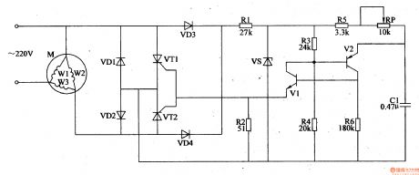
substitutive motor centrifugal switch circuit
Published:2011/7/16 19:55:00 Author:chopper | Keyword: centrifugal switch
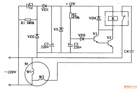
The principle of circuit The substitutive motor centrifugal switch circuit is formed by the power supply circuit and delay control circuit,which is shown in Figure 4-125. The power supply circuit is formed by the capacitor C1,discharge resistor R1,rectifier diodes VD1,VD2,filter capacitor C2 and voltage-regulator diode VS. Delay control circuit is formed by the resistor,capacitor C3,diodes VD3,VD4,transistors V1,V2,and the relay K. 20V AC voltage is dropped by C1,rectifiered by VD1 and VD2,filtered by C2 and regulated by VS,and then offer the delay circuit +12V operating power supply.
(View)
View full Circuit Diagram | Comments | Reading(3637)
Southeast Soveran windshield wiper and washer electrical system circuit
Published:2011/7/12 7:58:00 Author:John | Keyword: electrical system, windshield wiper, washer


View full Circuit Diagram | Comments | Reading(858)
crops automatic frost prevention controller(2)
Published:2011/7/15 20:55:00 Author:chopper | Keyword: frost prevention
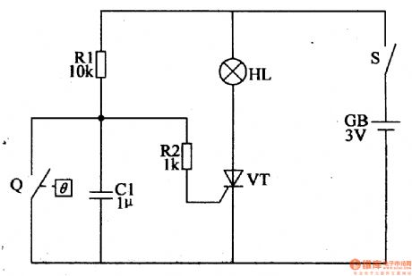
The principle of circuitThe crops automatic frost prevention controller circuit is formed by electric contact mercury thermometer Q,the control circuit and ignition device and other components, which is shown in figure 4-108.
What's the difference between the electric contact mercury thermometer and normal mercury thermometers is that in this mercury thermometer there are two platinum electrodes,and one is inserted in the contact electrode of the upper mercury warehouse,the other is inserted in the control electrode of temperature scale which is required control. It should set the measurement temperature (smoke combustion temperature) at +1 ℃ when it is in usage. (View)
View full Circuit Diagram | Comments | Reading(626)
Southeast Soveran windshield and mirror defogger electrical system circuit
Published:2011/7/12 8:24:00 Author:John | Keyword: windshield, mirror defogger, electrical system
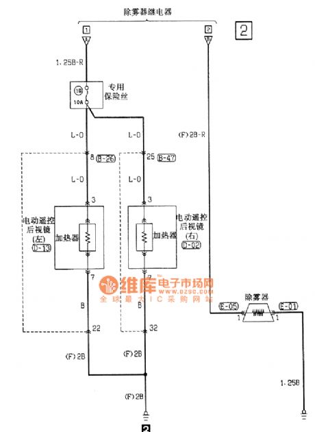
View full Circuit Diagram | Comments | Reading(930)
Nissan A32-AT circuit
Published:2011/7/17 2:19:00 Author:Fiona | Keyword: A32-AT
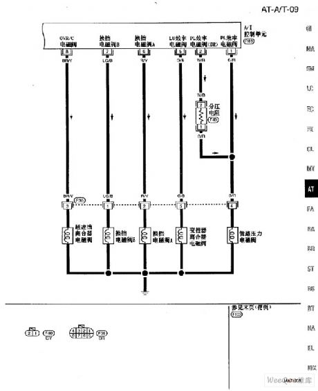
Nissan A32-AT circuit is shown as above:
(View)
View full Circuit Diagram | Comments | Reading(811)
Altima A33-EC VIAS circuit
Published:2011/7/17 2:16:00 Author:Fiona | Keyword: VIAS
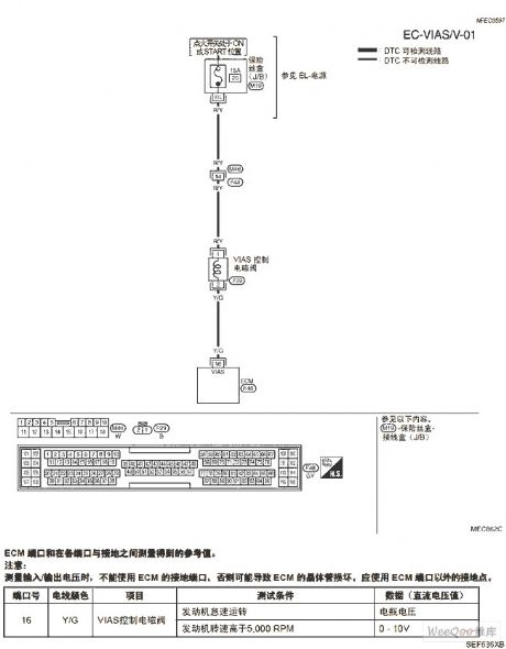
Altima A33-EC VIAS circuit is shown as above:
(View)
View full Circuit Diagram | Comments | Reading(807)
Altima A33-EC fuel pump circuit
Published:2011/7/17 2:15:00 Author:Fiona | Keyword: fuel pump
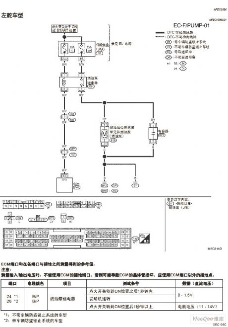
Altima A33-EC fuel pump circuit is shown as above:
(View)
View full Circuit Diagram | Comments | Reading(896)
zeropassage examination phase shifting trigger drive circuit
Published:2011/7/17 7:27:00 Author:Fiona | Keyword: zeropassage examination, phase shifting
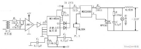
Zeropassage examination phase shifting trigger drive circuit is shown as above: (View)
View full Circuit Diagram | Comments | Reading(852)
Altima A33-EC refrigerant pressure sensor circuit
Published:2011/7/17 2:13:00 Author:Fiona | Keyword: refrigerant pressure sensor
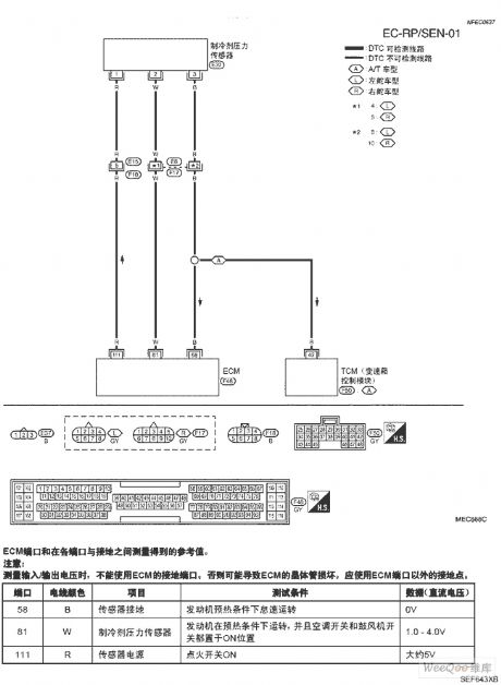
Altima A33-EC refrigerant pressure sensor circuit is shown as above:
(View)
View full Circuit Diagram | Comments | Reading(1305)
| Pages:1523/2234 At 2015211522152315241525152615271528152915301531153215331534153515361537153815391540Under 20 |
Circuit Categories
power supply circuit
Amplifier Circuit
Basic Circuit
LED and Light Circuit
Sensor Circuit
Signal Processing
Electrical Equipment Circuit
Control Circuit
Remote Control Circuit
A/D-D/A Converter Circuit
Audio Circuit
Measuring and Test Circuit
Communication Circuit
Computer-Related Circuit
555 Circuit
Automotive Circuit
Repairing Circuit