
Circuit Diagram
Index 1522
BA2181 touching stepping dimmer circuit
Published:2011/7/18 19:22:00 Author:Lucas | Keyword: touching stepping dimmer
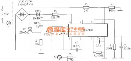
The touching steppingdimmer circuit shown as the chart uses BA2181 dimming ASIC, and it has the features of low power consumption, high anti-interference ability, stable and reliable, security work.
(View)
View full Circuit Diagram | Comments | Reading(587)
CS7232 touching stepless dimming light circuit (2)
Published:2011/7/18 19:01:00 Author:Lucas | Keyword: touching, stepless dimming light
In the circuit shown as the chart, it adds a metering circuit,which can be used totransform an ordinary lamp intospecial eye protection high-dimming lamp.
(View)
View full Circuit Diagram | Comments | Reading(675)
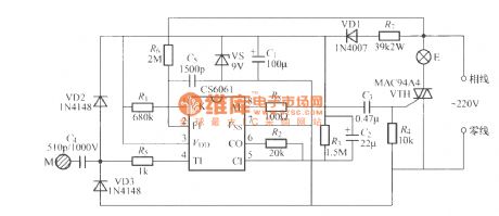
CS6061 touching stepping dimmer circuit
Published:2011/7/18 6:12:00 Author:Lucas | Keyword: touching stepping dimmer
View full Circuit Diagram | Comments | Reading(1007)
eyes care lamp(2)
Published:2011/7/17 20:36:00 Author:chopper | Keyword: care lamp
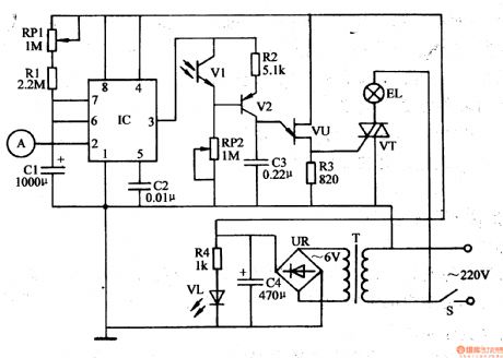
This example describes the eyes care lamp with functions like touch-sensitive light and turn off timing,and it can dim the light level according to the intensity of indoor light level automatically. The principle of circuitThe eyes care lamp circuit is formed by the power circuit, touch/timing control circuit and metering and dimming circuit,which is shown in Figure 1-19 The power circuit is formed by the power switch S,the power transformer T,bridge rectifier UR,filter capacitor C4,current limiting resistor R4 and the power indicative light-emitting diode VL.
(View)
View full Circuit Diagram | Comments | Reading(687)
eyes care lamp(1)
Published:2011/7/17 20:16:00 Author:chopper | Keyword: care lamp
This example describes the eyes care lamp, which has functions like automatic metering and manual dimming.when light is dim, the red LED lights, indicating that the light is not suitable for reading and writing, and it should increase the light level; and when the light is bright,the green LED lights to indicate that the area under the lamp is suitable for reading and writing. The principle of circuitThe eyes care lamp circuit is formed by the light metering/light intensity indication circuit and the light dimming circuit,which is shown in Figure 1-190.
(View)
View full Circuit Diagram | Comments | Reading(636)
crops automatic frost prevention controller(1)
Published:2011/7/15 20:42:00 Author:chopper | Keyword: frost prevention
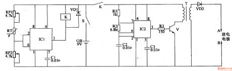
The principle of circuitThe crops automatic frost prevention controller circuitis formed by the temperature detection control circuit and high-voltage ignition circuit, which is shown in figure 4-107. Temperature detection control circuit is formed by the time-base integrated circuit IC1,potentiometers RP1,RP2,diode VD1, relay K and capacitor C1. High-voltage ignition circuit is formed by the time-base integrated circuit IC2, resistors R1-R3, capacitors C2,C3,transistor V, high-voltage transformer T,high-voltage rectifier diode VD2 and discharge electrodes A,B.
(View)
View full Circuit Diagram | Comments | Reading(585)
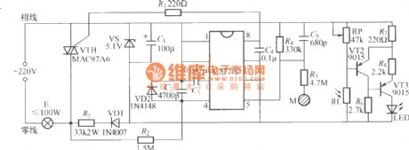
infrared remote control dimmable lamp
Published:2011/7/15 20:18:00 Author:chopper | Keyword: infrared, dimmable lamp
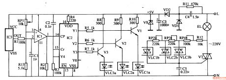
This example describes the infrared remote control dimmable lamp, which can use infrared remote controller of household appliances(such as televisions,DVD players,VCRs, etc.) to control,and it can open, turn off the light and dim(strong, medium, Weak 3 files) easily. The principle of circuit The infrared remote control dimmable lamp circuit is formed by the power supply circuit, infrared receiver amplification and dimming control circuit, which is shown in figure 1-201.
The power supply circuit is formed by the capacitor C4,discharge resistor Rll,rectifier diodes VD1,VD2,filter capacitor C3 and voltage-regulator diode VS.
(View)
View full Circuit Diagram | Comments | Reading(916)
seeder spray pipe water break alarm (3)
Published:2011/7/17 19:59:00 Author:chopper | Keyword: water break, alarm
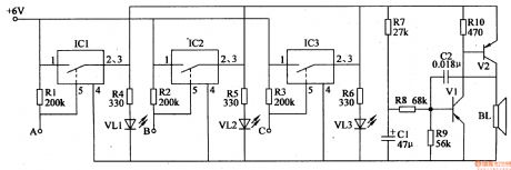
The principle of circuitThe seeder spray pipe water break alarm circuit is formed by the water break detection circuit and the sound and light alarm circuit,which is shown in Figure 4-1M The water break detection circuit is formed by the electronic switch integrated circuits IC1-IC3,and resistors R1-R3. Ends A-C are connected to 3 water pipes respectively. The sound and light alarm circuit is formed by the light-emitting diodes VL1-VL3,resistors R4-R10,capacitors C1,C2,transistors V1,V2,and the speaker BL. R4-R6 and VL1-VL3 compose of LED indicator circuit;the V1,V2,and C1,C2,R7-R10 form audio oscillator circuit.
(View)
View full Circuit Diagram | Comments | Reading(606)
wireless remote control dimmable lamp(2)
Published:2011/7/17 20:50:00 Author:chopper | Keyword: dimmable lamp, remote control
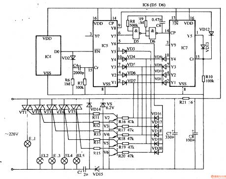
This example describes the wireless remote control dimmable droplight,which can control the working state of droplightat will.It not only cancontrol a certain lamp (or all lamps) to turn on or turn off, but also can make the various incandescent lamps in the droplight lighted in order circularly to produce the effect like water light . The principle of circuitThe wireless remote control dimmable droplight circuit is formed by the wireless remote control transmitter circuit and wireless remote control receiver circuit. Wireless remote control transmitter circuit is formed by the pulse encoder circuit and wireless transmitter circuit,which is shown in Figure 1-199
(View)
View full Circuit Diagram | Comments | Reading(611)
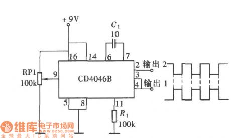
using CD4046 for composing symmetrical square-wave with contrast phase circuit
Published:2011/7/18 5:50:00 Author:John | Keyword: symmetrical square-wave, contrast phase
View full Circuit Diagram | Comments | Reading(4180)
Stable function generator circuit
Published:2011/7/18 5:55:00 Author:John | Keyword: function generator
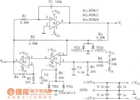
This circuit is a function generator, just as shown. Its square-wave output has a faster rise time and amplitude is not sensitive to temperature; In addition, its triangular output waveform has exactly the same changing rate in the whole range.
(View)
View full Circuit Diagram | Comments | Reading(580)
Generic function generator circuit
Published:2011/7/18 6:02:00 Author:John | Keyword: Generic function generator
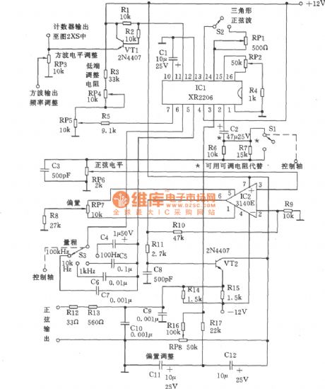
Signal generator can be divided into three parts. They are the sine wave and triangular wave generator, the counter and the pulse and ramp generator. As shown, XR2206 uses s voltage-controlled oscillator, whose frequency adjustment can be achieved by potentiometer RP5 (10k). It is easy to adjust the frequency to be within one-thousandth of the frequency or less. If you change the resistance of the fixed resistor R3, the resistance of RP5 can also be changed. Sine wave and triangular wave circuit is similar to other similar instruments. The different attenuation switch Sl only changes the amplitude of the signal, but can not affect the bias voltage.
(View)
View full Circuit Diagram | Comments | Reading(3516)
Single precision function generator ICL8038 application circuit (b)
Published:2011/7/18 6:06:00 Author:John | Keyword: Single precision function generator, application circuit
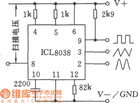
View full Circuit Diagram | Comments | Reading(951)
Single precision function generator ICL8038 application circuit (c)
Published:2011/7/18 6:07:00 Author:John | Keyword: Single precision function generator, application circuit
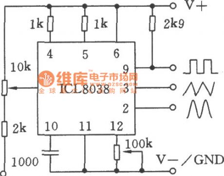
View full Circuit Diagram | Comments | Reading(2705)
NE566V generated sawtooth circuit
Published:2011/7/18 19:27:00 Author:John | Keyword: sawtooth, NE566V

View full Circuit Diagram | Comments | Reading(502)
Relay control for up-and-down slope circuit
Published:2011/7/12 9:54:00 Author:John | Keyword: Relay, up-and-down slope
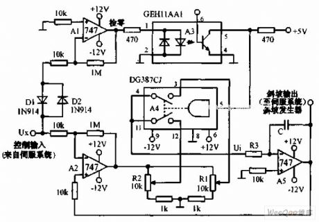
Relay control for up-and-down slope circuit is as shown, for which the DG387 CJ solid state relay has been used to achieve the switch from the upper slope to the lower slope. When the servo is at the new zero position, it slows down. The slope rate depends on the regulation position between R1 and R2. The circuit is with a low cost but to ensure the best response of the servo system. When input signal detected by A1 is not zero, the optical isolator A3 is started to drive the A4 to do the switch. Positive slope generated by A5 drives the system load to move towards the desired position. Thus, the control input voltage of servo feedback is driven to reduce input power.
(View)
View full Circuit Diagram | Comments | Reading(1529)
eyes care lamp(3)
Published:2011/7/17 20:36:00 Author:chopper | Keyword: care lamp
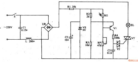
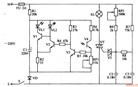
This example describes the eyes care lamp,which can dim the light level based on the intensity of indoor light level automatically. And it can protect the eyes and it is suitable for reading and writing. The principle of circuitThe eyes care lamp circuit is formed by the power circuit and optical control circuit,which is shown in Figure 1-192. Power supply circuit is formed by the power switch S, filter capacitors C1,C2,inductor L,bridge rectifier UR, current limiting resistor R1 and diode voltage regulator VS. The optical control circuit is formed by the photosensitive resistor RC, resistors R2-R4, potentiometer RP, capacitor C3, transistor V1,and dual-track trigger diode V2 and thyristor VT.
(View)
View full Circuit Diagram | Comments | Reading(654)
Video switch using MC1545 circuit
Published:2011/7/12 10:02:00 Author:John | Keyword: Video switch

Video switch using MC1545 circuit is as shown. MC1545 is the gated broadband amplifier, which is used as a video switch. The input is with differential mode. The door switch is used to convert two amplifiers A and B. A is selected to high electricity level and B is for low one. The output is also with differential output terminals. Gate input signal refers to TTL level, whose gated conversion time can be 20ns. When the gate signal is at high level, the video input signal is taken as an output signal. When the gate signal is at low level, the amplifier A is at the off state.
(View)
View full Circuit Diagram | Comments | Reading(637)
Video switch circuit
Published:2011/7/12 10:06:00 Author:John | Keyword: Video switch
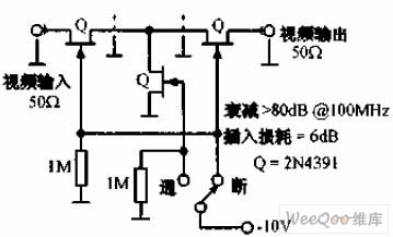
Video switch circuit is as shown. 2N4391 FET provides the circuit with only 30Ω induction -resistance and less than 0.2pF pinch-off is capacitance. This performance can be comparable with that of the ideal high-frequency switch. The attenuation for 100MHz circuit is more than 80dB and the insertion loss is about 6dB.
(View)
View full Circuit Diagram | Comments | Reading(757)
DPDT FET switch circuit
Published:2011/7/12 10:13:00 Author:John | Keyword: DPDT FET switch, FET
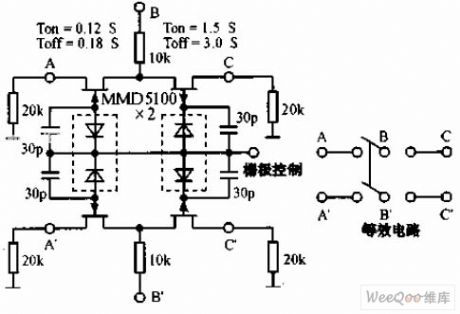
DPDT FET switch circuit is as shown. When the FET is inducted, the resistance of the drain channel can be up to thousands of MΩ. Therefore, FET can constitute an ideal low-frequency switch. Capacitance of ends of the FET is not good to do isolation for high-frequency signals. Thus, response time can be increased and maximum operating frequency can be limited.
(View)
View full Circuit Diagram | Comments | Reading(1298)
| Pages:1522/2234 At 2015211522152315241525152615271528152915301531153215331534153515361537153815391540Under 20 |
Circuit Categories
power supply circuit
Amplifier Circuit
Basic Circuit
LED and Light Circuit
Sensor Circuit
Signal Processing
Electrical Equipment Circuit
Control Circuit
Remote Control Circuit
A/D-D/A Converter Circuit
Audio Circuit
Measuring and Test Circuit
Communication Circuit
Computer-Related Circuit
555 Circuit
Automotive Circuit
Repairing Circuit