
Circuit Diagram
Index 1535
Motor light load energy saver 2
Published:2011/6/30 0:59:00 Author:Nicole | Keyword: motor, light load energy saver
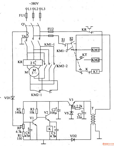
The motor light load energy saver circuit is composed of power supply circuit, current sampling detection circuit and control circuit, it is shown in the figure 8-2.
The power supply circuit is made of power transformer T, voltage regulation tube VS, rectifier diode VD2, resistor R4 and filter capacitors C1, C2.
The control circuit consists of power supply switch Q, stop button S1, starter button S2, transistors V1, V2, relay K, time relay KT, AC contactor KM1, KM2.
(View)
View full Circuit Diagram | Comments | Reading(1273)
Ozone disinfector 12
Published:2011/6/30 1:36:00 Author:Nicole | Keyword: ozone disinfector
The ozone disinfector circuit is composed of hand control/optical control convert circuit, delay control circuit, oscillator and high voltage generator circuit, it is shown in the figure 9-109.
The hand control/optical control convert circuit is made of photosensitive diode VD1, transistor V1, transfer switch S2, hand control button S1, resistor R1.
The delay control circuit consists of six not gates integrated circuit IC, resistor R3, capacitors C2, C3 and diodes VD2, VD3.
The oscillator circuit is composed of IC and resistors R2, R4, potentiometer RP, capacitor C4.
(View)
View full Circuit Diagram | Comments | Reading(929)
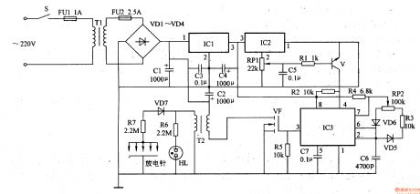
Music socket circuit diagram with infrared sensor application-specific integrated circuit using KC778B
Published:2011/5/17 3:17:00 Author:Ecco | Keyword: Music socket, application-specific integrated circuit , infrared sensor
The chart shows the music socket circuit diagram with infrared sensor specific integrated circuit using KC778B. KC778B is a type of infrared sensor specific integrated circuit which is supported to use with pyroelectric infrared sensors, and they could be used as automatic lights, automatic doors, automatic electric fans, air conditioning, automatic release device and security alarm system. (View)
View full Circuit Diagram | Comments | Reading(1648)
Ozone disinfector 10
Published:2011/6/30 1:16:00 Author:Nicole | Keyword: ozone disinfector
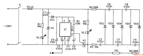
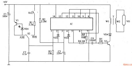
The ozone disinfector circuit is composed of delay circuit, power supply circuit, double-pressure ozone generation circuit and some correlative components, it is shown in the figure 9-107.
The delay circuit is made of time base integrated circuit IC and capacitors C2, C4.
The power supply circuit consists of steady voltage diode VS, rectifier diode VD1, capacitors C1, C0.
The double-pressure ozone generation circuit is composed of rectifier diode VD2-VD6, capacitors C5-C9, resistor R6, ozone tube VG.
(View)
View full Circuit Diagram | Comments | Reading(990)
The control circuit diagram of optical coupler electrical heating
Published:2011/5/9 21:25:00 Author:Ecco | Keyword: control circuit, optical coupler , electrical heating
The pulse output from pulse oscillator reachesthe positive electrode of the light-emitted diode in the solid by LED. The luminous intensity of LEDis changed with pulse duty factor. Then the breakover degree of photo-thyristor is changed to realize the purpose of constant temperature control.
The pulse oscillator is composed of trigger circuit and constant temperature control circuit of solid relay. The pulse oscillator in the circuitry is a type of oscillator with steady frequency and adjustable pulse duty factor. To regulate the charging and discharging time of convertibility capacitance C1 by changing RP, then the pulse duty factor is changed. While needing to raise heat temperature, the RP can be turned right in the chart to relay the charging time of C1; Or the RP can be turned left may decrease the discharging time of C1. The period of surge in the circuitry is 1255, and account for the range of O. 4%~99. 6% in adjustable pulse duty factor. (View)
View full Circuit Diagram | Comments | Reading(602)
Ozone disinfector 9
Published:2011/6/30 1:08:00 Author:Nicole | Keyword: ozone disinfector
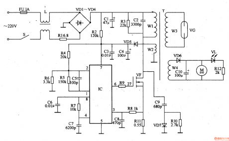
The ozone disinfector circuit is composed of power supply input circuit, switch oscillation circuit, fan circuit and ozone generator circuit, it is shown in the figure 9-106.
The power supply input circuit is made of fuse FU, power supply switch S, filter inductor L, current limiting resistor R1, rectifier diodes VD1-VD4 and filter capacitor C1.
The switch oscillation circuit consists of PWM switch power supply control integrated circuit IC, resistors R2-R11, capacitors C2-C9, diodes VD5, VD7, FET VF and the W1, W2 winding of switch pulse transformer T.
(View)
View full Circuit Diagram | Comments | Reading(3624)
The low-light amplifier circuit diagram
Published:2011/5/13 4:13:00 Author:Ecco | Keyword: low-light amplifier
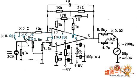
This circuitry is usedas the amplifier circuitry that the range is 21X and 20 IX, if the range is higher than 200 IX, it can be settled by paralleling connecting resistance by a header directly. In order to assure linear feature, when it measures a 20 IX tick, the burdenof 2 CR diminishes because of paralleling connecting resistor in 3.9 K Ω, and the error is about ±4%; The stability changes ±endless% annually, but it is effected by temperature, and increasing 1 ℃ JF each time, the value will enlarge 1%.
(View)
View full Circuit Diagram | Comments | Reading(709)
The status indicating circuit diagram of serial interface of computer
Published:2011/5/9 21:31:00 Author:Ecco | Keyword: status indicating circuit, serial interface, computer
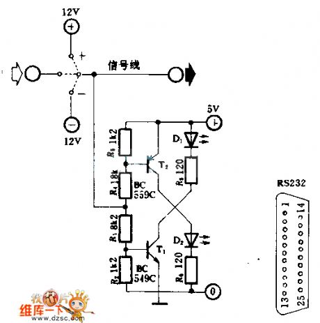
The construction of circuitry is simple, and there are only 6 resistances, 2 transistors and 2 light-emitted diodes, used as status indicating of serial interface of computer RS-232. When D1 is lit, it means the logic is 0 , the connecting voltage is about 4.5~5.5V; When geting semaphore, the power cost is about 27mA.
(View)
View full Circuit Diagram | Comments | Reading(557)
Negative oxygen ion generator 3
Published:2011/6/28 1:23:00 Author:Nicole | Keyword: oxygen ion, generator
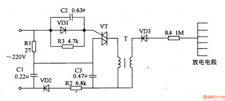
This negative oxygen ion generator circuit is composed of TRIAC VT, diodes VD1-VD3, resistors R1-R4, capacitors C1-C3, boost transformer T and electrode pad, it is shown in the figure 9-115.
The bleeder circuit is made of R1 and C1, the phase shift trigger circuit consists of VD1, C2, R3.
At the negative half-cycle of AC, rectifier diode VD2 turns on, after rectifying, the pulse DC voltage charges to C3 by R2, when the both sides of C3's voltage reaches peak value, VT is triggered and turned on. When the AC passage zero, due to C2's phase shift action, C2's voltage also can make VT turned on.
(View)
View full Circuit Diagram | Comments | Reading(2972)
74 series digital circuit of 74L51 and 74LS51 2 input/3 output and-nor gate
Published:2011/5/17 3:23:00 Author:Ecco | Keyword: digital circuit, 2 input, 3 output, and-nor gate
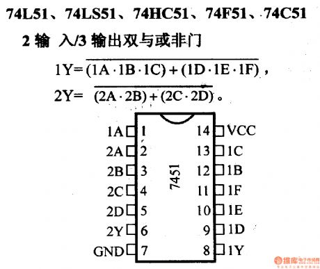
74L51, 74LS51, 74HC51, 74F51, 74C51 2 and-nor gate
(View)
View full Circuit Diagram | Comments | Reading(949)
Pulse shaping circuit composed of gate circuit(CD4069)
Published:2011/5/17 4:00:00 Author:Ecco | Keyword: Pulse shaping circuit , gate circuit
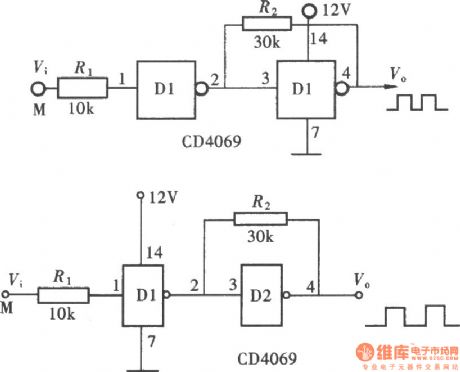
As CMOS gate having a fixed threshold level, the part lower than the threshold of the signal pulse has no responding to the input end of gate circuit. Using this feature, it can be directly used in the pulse shaping. In practical electronic circuits, integrated gate circuit is one of the most practical one. It's used as a control gate, also used to form the clock pulse generator. As an integrated gate circuit often contains several independent gates, so there are always some spare parts besides the main structure of the circuits. And they can use these extra parts to make the pulse shaping, RP, amplifier and so on. For some high demanding circuits, the direct use of plastic gate can not meet the requirements, but it will form a Schmitt trigger gate, the using of Schmitt trigger hysteresis make the pulse shaping circuits meet the requirements, this structure of the circuit is shown as the chart. (View)
View full Circuit Diagram | Comments | Reading(1595)
Multi-function refrigerator controller composed of 555
Published:2011/5/12 2:20:00 Author:Ecco | Keyword: Multi-function , refrigerator , controller , 555
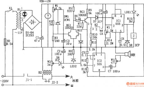
The chart shows the multi-function refrigerator controller. The controller consists of over voltage, under voltage sampling circuit, delay-start circuit, sound and light alarm circuit, buck rectifier circuit. Buck rectifier circuit provides DC voltage for the entire controller. Delay start circuit consists of IC1 (555) and C6, R14, W3, etc, when turning on or getting power after power failure, the terminal voltage of C6 can not be mutated, 555 occurs resetting as pin ⑥ being in high potential, with the charging, C6 makes the potential of pin 2 be less than 1/3VDD, the 555 occurs setting, high output of pin③ makes the relay pull in. The corresponding delay is td = 1.1 (Rw3 + R14) C6, the icon corresponding delay parameter is about 4 to 10 minutes. Overvoltage, undervoltage and overcurrent detection, switch circuit consists of W1, R2, R3, DW1, BG1, BG2, BG3 and so on. When occurring overvoltage, undervoltage or over-flow, BG3 is off, its collector is in high potential, the potential is added to the pin ⑥ of IC1, and 555 resets, the low output of pin ③ makes the relay J release, contact J2-2 cut off, the power of the refrigerator cut off, while LED1 is lit; the other way, the partial pressure passing the R10, R1 added to the pin ④, of IC2, IC2 starts oscillation. (View)
View full Circuit Diagram | Comments | Reading(2072)
Zero-voltage motor open-phase protection circuit diagram
Published:2011/5/17 3:31:00 Author:Ecco | Keyword: Zero-voltage, motor, protection circuit, open-phase

Figure 141 shows the Zero-voltage motor open-phase protection circuit diagram. When running motor occurs single-phase outage, the protection device can automatically cut off power to avoid motor occuring open-phase running. Working principle: when normal operation, the potential of the three-phase power balance point E is zero.
(View)
View full Circuit Diagram | Comments | Reading(1708)
Infrared sensing automatic door control circuit diagram with KC778B
Published:2011/5/17 3:16:00 Author:Ecco | Keyword: Infrared sensing , automatic door , control circuit
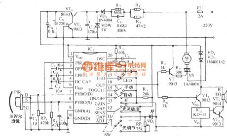
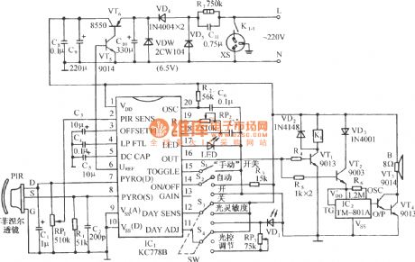
The circuit is shown as the chart. It is a control circuit which composed of infrared specific integrated circuit KC778B and KC778B is the center of the circuit. It’s surrounded by a pyroelectric infrared sensor head PIR, light control and light control adjustment circuit, a three-state select control, automatic restart function and manual control block status sensing functions and so on. (View)
View full Circuit Diagram | Comments | Reading(4178)
Mobile detector
Published:2011/5/13 4:27:00 Author:Ecco | Keyword: Mobile, detector

The up circuit is ultrasonic receiver and signal processing circuit, the transmitting circuit is as below. (View)
View full Circuit Diagram | Comments | Reading(1307)
Negative oxygen ion generator 2
Published:2011/6/28 1:07:00 Author:Nicole | Keyword: oxygen ion, generator
This negative oxygen ion generator circuit is composed of power supply circuit, humidity detection circuit, oscillator and high voltage generator, it is shown in the figure 9-114.
The power supply circuit is made of power supply switch S, fuse FU1, FU2, power transformer T1, rectifier diodes VD1-VD4, fliter capacitors C1-C3, there terminals integrated regulator IC1.
The humidity detection circuit consists of integrated circuit IC2, control tube V, potentiometer RP1, resistor R1 and capacitor C5.
The oscillator is composed of time base integrated circuit IC3 and peripheral devices.
(View)
View full Circuit Diagram | Comments | Reading(2151)
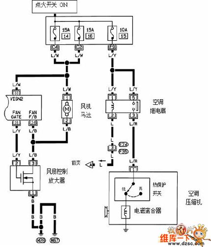
Nissan T30 air conditioning system circuit diagram--petrol and diesel engine circuit diagram
Published:2011/5/9 21:26:00 Author:Ecco | Keyword: air conditioning system, petrol engine, diesel engine
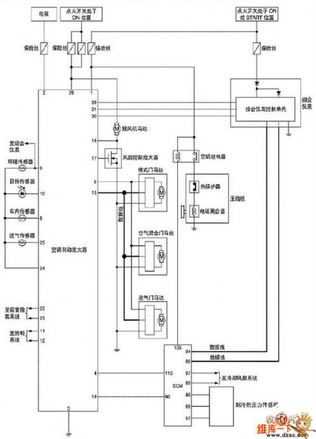
Nissan T30 air conditioning system circuit diagram--petrol and diesel engine circuit diagram is as below:
(View)
View full Circuit Diagram | Comments | Reading(928)
Dong Feng Nissan photic air-condition system circuit diagram
Published:2011/5/9 21:28:00 Author:Ecco | Keyword: photic air-condition
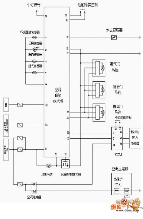
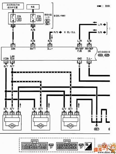
Dong Feng Nissan photic air-condition system circuit diagram is as below:
(View)
View full Circuit Diagram | Comments | Reading(560)
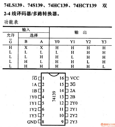
74 series digital circuit of 74LS139 and 74S139 2-4 line decoder/multi-channel converter
Published:2011/5/17 3:18:00 Author:Ecco | Keyword: digital circuit , 2-4 line decoder, multi-channel converter
View full Circuit Diagram | Comments | Reading(2898)
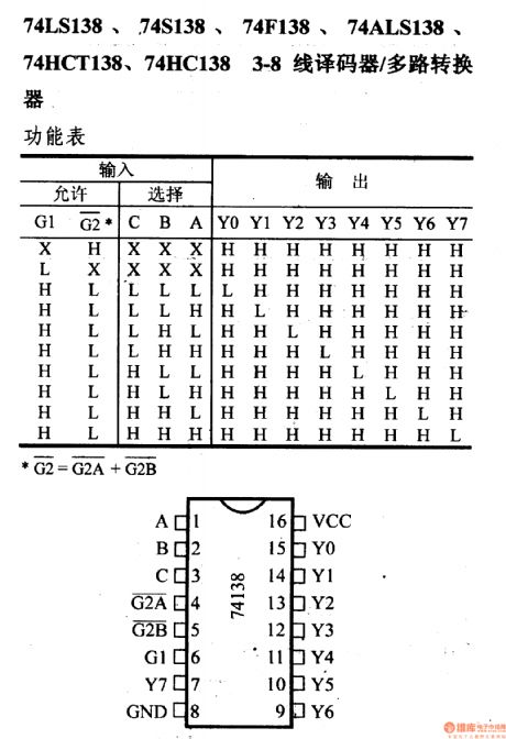
74 series digital circuit of 74LS138 and 74S138 3 - 8 line decoder/multiplexer
Published:2011/5/17 3:19:00 Author:Ecco | Keyword: digital circuit, 3 - 8 line decoder, multiplexer
View full Circuit Diagram | Comments | Reading(4424)
| Pages:1535/2234 At 2015211522152315241525152615271528152915301531153215331534153515361537153815391540Under 20 |
Circuit Categories
power supply circuit
Amplifier Circuit
Basic Circuit
LED and Light Circuit
Sensor Circuit
Signal Processing
Electrical Equipment Circuit
Control Circuit
Remote Control Circuit
A/D-D/A Converter Circuit
Audio Circuit
Measuring and Test Circuit
Communication Circuit
Computer-Related Circuit
555 Circuit
Automotive Circuit
Repairing Circuit