
Circuit Diagram
Index 1518
Charger Circuit of BP2002
Published:2011/7/16 10:18:00 Author:Michel | Keyword: Charger Circuit
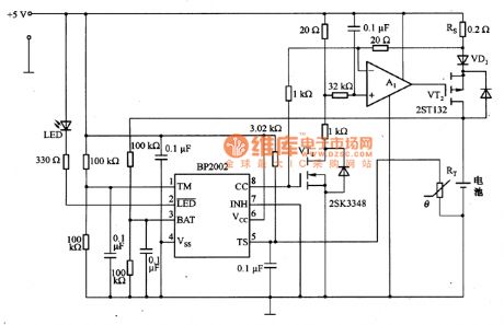
Picture 9 is charger circuit of BP2002.When the longest charging time is 160 minutes,the timer acts.Thermistors RT is used to test the temperature of the battery charging and it is close to the surface of charging batteries. When the temperature of the battery is 60 ℃,the battery stops charging.When it is fast charging, the current flows through the Rs is 490 mA. It produces 98 mV voltage drop and produces 0.2V voltage drop on VD1.After fast charging,it compensates for the charging for 16O minutes and then it continuously supplements the charging in C/64 rate. (View)
View full Circuit Diagram | Comments | Reading(757)
Charger Circuit of LM317
Published:2011/7/16 11:03:00 Author:Michel | Keyword: Charger Circuit
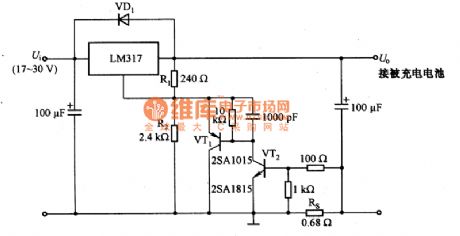
The above picture is charger picture of LM317.It adopts LM317 constant current to charge and its input voltage Ui is +17~+30V and the output voltage is U.The largest voltage is 3.8V and largest current is 1A.The output voltage is same with termination voltage of charged battery,they are set by dividing resistor R1 and R2.RS tests output current and VT1 and automatically adjust the LM317,thus output voltage is consistent with battery terminal voltage.And it outputs constant current which is about 1 A.RS resistance obeys the following formula, namely RS = UBE / 1 A = 0.7 V / 1 A ≈ 0.7 Ω and it chooses 0.68Ω in the circuit (View)
View full Circuit Diagram | Comments | Reading(3277)
The MOSFET drive circuit
Published:2011/7/17 22:33:00 Author:Borg | Keyword: MOSFET drive
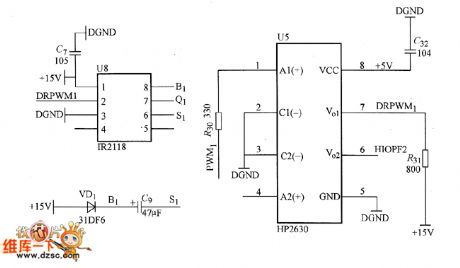
The drive core is MOSFET specialized drive core IR2118 which is produced by IR Corp., it is a single line drive; the photoelectric clutch, which can separate the electricity from light and improve the voltage function, is the HP2630 which is produced by HP Corp. The PWM output by DSP is driving IR2118 after it is separated by the photoelectric coupler HP2630, and then the signal output by IR2118 is driving MOSFET. Notes: only when the voltage is over 9.5V, does IR2118 regard it as the high LEV, or it is the low LEV, the circuit is shown in the figure.
(View)
View full Circuit Diagram | Comments | Reading(1287)
The dashboard circuit of Buick-Regal (4)
Published:2011/7/17 22:57:00 Author:Borg | Keyword: dashboard, Buick-Regal
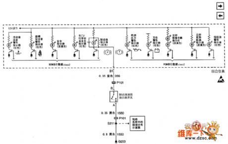
Figure 1:The dashboard circuit of Shanghai GM Buick-Regal (4) (View)
View full Circuit Diagram | Comments | Reading(494)
The dashboard circuit of Buick-Regal (5)
Published:2011/7/17 22:54:00 Author:Borg | Keyword: dashboard, Buick-Regal
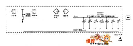
Figure 1:The dashboard circuit of Shanghai GM Buick-Regal (5) (View)
View full Circuit Diagram | Comments | Reading(419)
The burglarproof alarm circuit of Buick-Regal
Published:2011/7/17 23:00:00 Author:Borg | Keyword: burglarproof alarm circuit
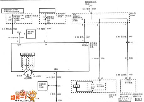
figue 1:Theburglarproof alarmcircuitofShanghaiGMBuick-Regal (View)
View full Circuit Diagram | Comments | Reading(461)
The eye lens system circuit of Buick-Regal
Published:2011/7/17 23:07:00 Author:Borg | Keyword: eye lens system, Buick-Regal
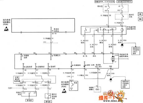
Figure 1: The eye lens system circuit ofShanghai GM Buick-Regal--3.0L (View)
View full Circuit Diagram | Comments | Reading(530)
The backup assisting system circuit of Buick-Regal
Published:2011/7/17 23:03:00 Author:Borg | Keyword: backup assisting system, Buick-Regal
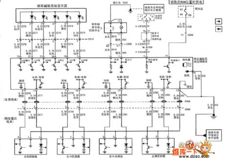
figure: The backup assisting system circuit of Buick-Regal--3.0L (View)
View full Circuit Diagram | Comments | Reading(523)
Automatically Charging Circuit of Battery
Published:2011/7/16 11:25:00 Author:Michel | Keyword: Battery Charging Circuit
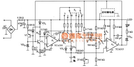
The above picture is automatically charging circuit of battery.This circuit consists of constant current circuit and automatically cut-off the circuit etc.A1 makes both ends of RL keep the same,which ensures constant charging current IZ.VDZ1 provides 18 V benchmark voltage for the base of VDZ1,It produces constant voltage drop on R2, the voltage drop is added to phase input terminal of A1.After the comparison of A1 and RL voltage drop,IZ keeps constant value.When RL is in short-circuit, resistance R3 of the output end will cut off VT3 base current and charging current IZ will be cut off sequently to protect the circuit.Functions of VD4 and VD5 are that prevent batteries discharging via VT3 when the charger cuts off. (View)
View full Circuit Diagram | Comments | Reading(1112)
Isolation Regulated Power Supply Circuit of NE555
Published:2011/7/16 21:55:00 Author:Michel | Keyword: Regulated Power Supply Circuit
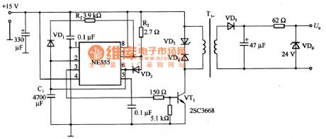
The picture is isolation regulated power supply circuit of NE555.In the circuit,R1 and R2 adjust and drive the conduction and off time of VT1.When R1 = R2,feet 3 of NE555 outputs rectangular wave with 50% dutyfactor but actually VT1 conduction is a little late, thus it needs to be adjusted lightly.VT1 conduction time is determined by R2 and C1 and the deadline depends on C1 and R1.When output voltage is high PWL,the charging time is t1 and the dischrging time is t2 when it is low PWL and t1=0.693R2C1(s),t2=0.693R1C1(s). (View)
View full Circuit Diagram | Comments | Reading(1410)
The 4T65E auto speed changer circuit of Shanghai GM Buick-MPV (2)
Published:2011/7/18 21:00:00 Author:Borg | Keyword: auto speed changer, Buick-MPV
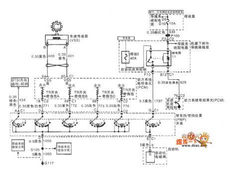
The 4T65E auto speed changer circuit of Shanghai GM Buick-MPV (2)
(View)
View full Circuit Diagram | Comments | Reading(485)
The 4T65E auto speed changer circuit of Shanghai GM Buick-MPV (3)
Published:2011/7/18 21:01:00 Author:Borg | Keyword: auto speed changer, Buick-MPV
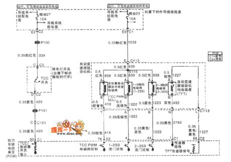
The 4T65E auto speed changer circuit of Shanghai GM Buick-MPV (3)
(View)
View full Circuit Diagram | Comments | Reading(1213)
The auto speed changer circuit of Shanghai GM Buick-Regal (1)
Published:2011/7/18 20:58:00 Author:Borg | Keyword: auto speed changer, Buick-Regal
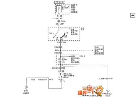
Figure 1. The auto speed changer circuit of Shanghai GM Buick-Regal (1) (View)
View full Circuit Diagram | Comments | Reading(441)
The auto speed changer circuit of Shanghai GM Buick-Regal (2)
Published:2011/7/18 20:56:00 Author:Borg | Keyword: auto speed changer, Buick-Regal
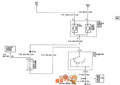
Figure 1. The auto speed changer circuit of Shanghai GM Buick-Regal (2) (View)
View full Circuit Diagram | Comments | Reading(464)
The auto speed changer circuit of Shanghai GM Buick-Regal (3)
Published:2011/7/18 20:54:00 Author:Borg | Keyword: auto speed changer, Buick-Regal
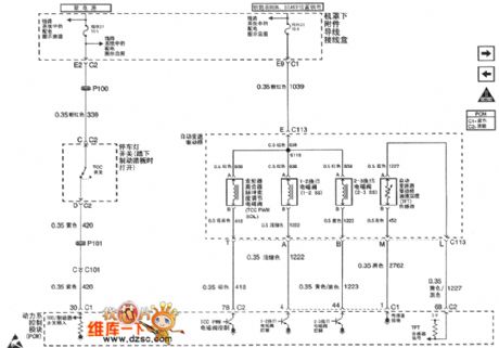
Figure 1. The auto speed changer circuit of Shanghai GM Buick-Regal (3) (View)
View full Circuit Diagram | Comments | Reading(446)
Regulated Power Supply Circuit with 42V/500mA Output
Published:2011/7/16 22:40:00 Author:Michel | Keyword: 42V/500mA Output, Regulated Power Supply Circuit
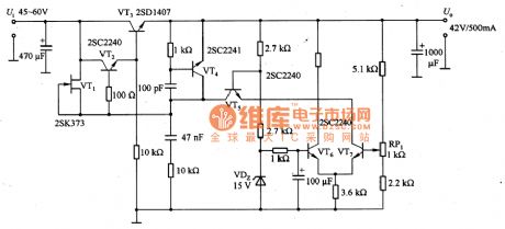
The above picture is regulated power supply Circuit with 42V/500mA output.In the circuit, VT1 adopts UDS = 1 of OOV mosfet 2 SK373 to constitute a high voltage constant current source.Besides the field effect tube,constant current diode E-202 is also avaliable.Largest work voltage of E-202 is 1OOV and its rated power is 3 OmW.VT6 and VT7are error amplifiers and they use the UcEo. 2SC2240 is 12OV high pressure transistor and VT5 constitutes cascode amplifier to improve frequency characteristics of the error amp. (View)
View full Circuit Diagram | Comments | Reading(1642)
The auto speed changer circuit of Shanghai GM Buick-Regal (4)
Published:2011/7/18 20:52:00 Author:Borg | Keyword: auto speed changer, Buick-Regal
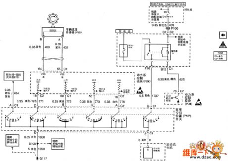
Figure 1. The auto speed changer circuit of Shanghai GM Buick-Regal (4) (View)
View full Circuit Diagram | Comments | Reading(431)
The ABS GND and ABS/traction control unit circuit of Shanghai GM Buick-MPV (GL8)
Published:2011/7/18 20:45:00 Author:Borg | Keyword: ABS, GND, Buick-MPV
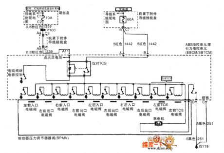
The ABS GND and ABS/traction control unit circuit of Shanghai GM Buick-MPV (GL8)
(View)
View full Circuit Diagram | Comments | Reading(539)
The auto speed changer circuit of Shanghai GM Buick-Regal (5)
Published:2011/7/18 20:50:00 Author:Borg | Keyword: auto speed changer, Buick-Regal
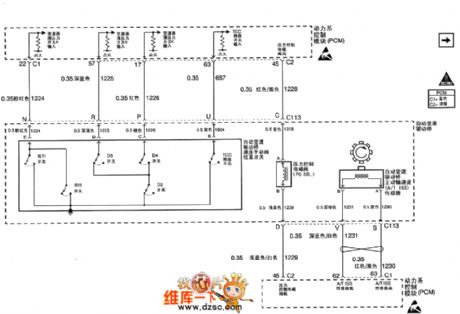
Figure 1. The auto speed changer circuit of Shanghai GM Buick-Regal (5) (View)
View full Circuit Diagram | Comments | Reading(403)
Regulated Voltage Power Supply Circuit of MC33363
Published:2011/7/17 5:23:00 Author:Michel | Keyword: Regulated Voltage, Power Supply Circuit
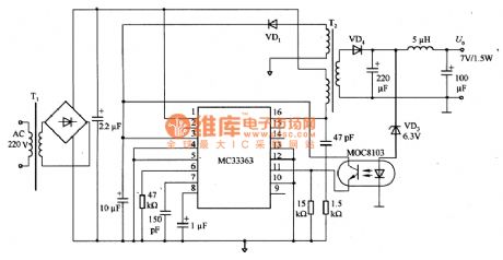
The picture 54 is regulated voltage power supply circuit of MC33363.MC33363 in the circuit is intergrated controller with gradual pulse current tester.In this application circuit,feet 10 (feedback) reaches the ground and the intergrated controller can work when it is the biggest dutyfactor(50%).When the primary level reaches the maximum limit,each output pulse is cut off.The biggest advantage of thr controller is that it can control the peak value and oscillation frequency.
(View)
View full Circuit Diagram | Comments | Reading(1490)
| Pages:1518/2234 At 2015011502150315041505150615071508150915101511151215131514151515161517151815191520Under 20 |
Circuit Categories
power supply circuit
Amplifier Circuit
Basic Circuit
LED and Light Circuit
Sensor Circuit
Signal Processing
Electrical Equipment Circuit
Control Circuit
Remote Control Circuit
A/D-D/A Converter Circuit
Audio Circuit
Measuring and Test Circuit
Communication Circuit
Computer-Related Circuit
555 Circuit
Automotive Circuit
Repairing Circuit