
Circuit Diagram
Index 1569
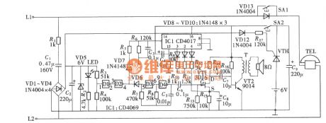
Visitor Identified Doorbell Circuit
Published:2011/7/8 1:07:00 Author:Joyce | Keyword: Visitor Jdentified , Doorbell
Here, a visitor could be a family member, an acquaintance or a stranger. The reason why the doorbell can differentiate the identity of visitors is not only due to the special design of the circuit structure, but also taking advantage of the psychology and the common habits of people. The doorbell can be divided into three groups: single button, two buttons and three buttons. To strangers who don’t know the inside well, he won't press two or three buttons at the same time, but he will press one of buttons, which will not trigger the doorbell. (View)
View full Circuit Diagram | Comments | Reading(913)
Transceiver module of the telephone wireless ringing circuit composed of RCMlA/RCMlB
Published:2011/7/8 5:57:00 Author:TaoXi | Keyword: Transceiver module, telephone, wireless ringing circuit
The transmitter directly connects to the telephone line in parallel mode, and this device does not need the external power supply. The isolation effect of the capacitance C1 makes the launcherdo not affect the normal work of the telephone.
(View)
View full Circuit Diagram | Comments | Reading(735)
Fan remote control speed regulation circuit TX315B1
Published:2011/7/8 5:57:00 Author:TaoXi | Keyword: Fan speed, remote control, speed regulation
Fan remote control speed regulation circuit TX315B1
(View)
View full Circuit Diagram | Comments | Reading(837)
Remote control discoloration droplight TDC1808/TDC1809
Published:2011/6/14 2:52:00 Author:TaoXi | Keyword: Remote control, discoloration, droplight
Each time when you press the button, the mute signal output terminal MUTE will output the low-level voltage to make the external light emitting diode to flash one time as the output instruction. The coded signal is sent out by the MK5087's TONE port and this signal gets to the launch component TDC1808 through resistance R2; in the receiving circuit, the receiving & demodulation output signal of the TDC1809 receiving component is decoded by the YN9102 DTMF decoder, the binary code that is sent out by the D1~D4 ports (corresponding to the launch instruction encoding phase) can be controlled by the SCR, then SCR controls the 4 kinds of color of colored lights.
(View)
View full Circuit Diagram | Comments | Reading(896)
70MHz Paralleled Crystal Oscillator Circuit
Published:2011/6/30 4:18:00 Author:Joyce | Keyword: 70MHz , Paralleled, Crystal Oscillator
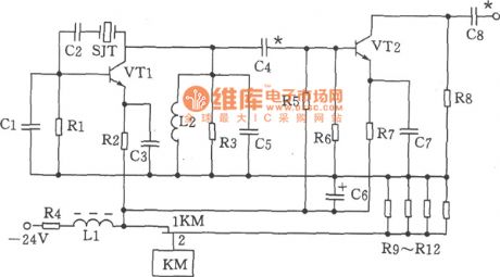
As shown in the figure is the 70MHz paralleled crystal oscillator circuit. The oscillator is mainly composed of transistor VT1, crystal SJT ,capacitance C1、 C5 and other components.
Choices of components:
Capacitance C1 is 20p, C2 is 100p, C3, C7 is 820p, C4 is 56p, C5, C8 is 47p, and C6 is 47u F / 50V. Inductance DLL for μ22 H (color code inductance), L2 is 0.3 μH. Resistance R1 is 1.6 kΩ ,R2 is
1kΩ, R3 is 750Ω and R4 is 180Ω,1W, R5 is 1.3 Ω , R6 is 3kΩ ,R7 is 360Ω, R8 is 470 Ω, R9 ~ R12 is 300Ω, 2W . Choices for transistor VT1, VT2 could be 3DG828 ,65≤β≤115. Crystal SJT could use model JA98-70MHz. Relays KM is JUC - 1M. (View)
View full Circuit Diagram | Comments | Reading(670)
48MHz HCMOS Oscillator Circuit
Published:2011/6/30 4:17:00 Author:Joyce | Keyword: 48MHz , HCMOS , Oscillator

As shown in the figure is a 48MHz crystal oscillator composed of HCMOS integrated circuit. The fundamental frequency of the crystal is 16MHz, but the oscillator is compelled to work on triple frequency harmonic. The importance of harmonic oscillator is to inhibit the fundamental frequency of the crystal. The parallel resonant circuit in the graph will resonate on the basis of the fundamental frequency of the crystal, when it is connected with crystal and SJT in series, the impedance to the fundamental frequency will be the highest, thus it can effectively refrain the fundamental frequency from oscillation and ensure the oscillation of the triple frequency harmonic. (View)
View full Circuit Diagram | Comments | Reading(873)
Power Amplifier Circuit Made of LM317
Published:2011/7/8 0:40:00 Author:Joyce | Keyword: Power Amplifier
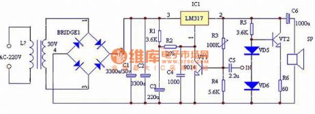
This circuit is Pure Class A, and using a low noise tube as its voltage amplifier, so the THD, NF indexs are quite good. Its output power can reach 30 W. As shown in the figure, VT1 transistor is used as voltage amplifier, because the input impedance of the integrated circuit IC1 is high, the working current of 0.6 mA is enough. R1, C3 are power decouplings, and C4 is used to prevent parasitic oscillation. R3, R4 will divide pressure to provide offset and ac/dc feedback to VT1 to improve the linearity and dc stability. VT2, R5, R6 and diode form a constant flow source, which is used to improve the efficiency and output power of the circuit, and increase the output dynamic range. (View)
View full Circuit Diagram | Comments | Reading(4832)
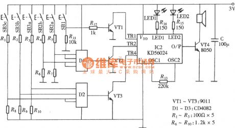
Sirens Generator Circuit Composed of Gate Circuit
Published:2011/7/8 8:36:00 Author:Joyce | Keyword: Sirens Generator, Gate Circuit
A multivibrator with sirens composed of gate circuit can drive LEDs to generate a great amount of changing colors. Pulse output through multivibrator can drive the speaker to produce sound. Signals with one frequency can make the speaker produce sound with single frequency; Signals with several frequencies can make it produce different sounds. According to this principle, one can have a mix of signal sources with different frequency to obtain the various sounds needed. As shown in the figure l is the siren generator composed of gate circuit. (View)
View full Circuit Diagram | Comments | Reading(1071)
The High confidentiality electronic lock circuits T630 and T631
Published:2011/6/14 2:50:00 Author:TaoXi | Keyword: High confidentiality, electronic lock
You can use the jump yard decoding circuit to form the high confidentiality electronic lock that can be used in the safety deposit box, the confidential file cabinet, the confidential room applications to ensure their safety. The high confidentiality electronic lock circuit which is composed of the jump yards decoding circuit (ACM1330E/ACM1550D) and the long-wave remote control transmitter / receiver circuit (T630/T631) is as shown in the figure. (a) is the coded excitation circuit; (b) is the receiving decoder circuit.
(View)
View full Circuit Diagram | Comments | Reading(802)
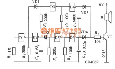
Twitter Generator Circuit Composed of CD4046
Published:2011/7/8 1:04:00 Author:Joyce | Keyword: Twitter, Generator
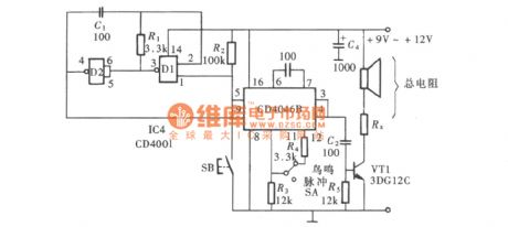
As shown in the figure is the twitter generator circuit composed of CD4046 (View)
View full Circuit Diagram | Comments | Reading(3166)
The Multichannel wireless remote control circuits F36-F and F36-J
Published:2011/6/14 2:50:00 Author:TaoXi | Keyword: Multichannel, wireless remote control
This circuit uses the multichannel wireless remote control circuit which is composed of the F36-F and F36-J. In the transmission circuit, we use the DTMF coding & decoding circuit to change the launch button input signal into the 4-bit binary code and then input this signal to the F36-F to send out. In the receiving circuit, the F36-J receives the remote control signal and changes this signal into the 4-bit binary code, then changes this 4-bit binary code into the channel control signal through a four-sixteen line decoder to control the corresponding circuit.
Theremote controltransmission circuit:
The receiver decoding circuit:
(View)
View full Circuit Diagram | Comments | Reading(832)
Phase Shift Alarm Generator Circuit Composed of CD4046
Published:2011/7/8 1:03:00 Author:Joyce | Keyword: Phase Shift , Alarm , Generator
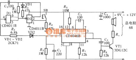
As shown in the circuit is the phase shift alarm generator circuit composed of CD4046 (View)
View full Circuit Diagram | Comments | Reading(1840)
Alarm Generator Circuit Composed of CD4046
Published:2011/7/8 1:03:00 Author:Joyce | Keyword: Alarm , Generator
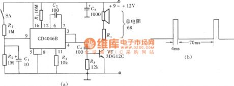
The voltage-controlled oscillator installed within CD4046 has very good practicability. Though its internal circuit structure is very complex, the usage is quite simple. While using CD4046, through regulating the control voltage of its foot ⑨, one can make the oscillation frequency of the vco varies in a wide range. And controlling its feet⑤ can make it start or stop oscillation easily. This structure of the circuit gives it a unique advantage in all kinds of alarm circuit. As shown in the figure is the alarm generator composed of CD4046. (View)
View full Circuit Diagram | Comments | Reading(4719)
The Children lost warning devices NE555 and TDA7000
Published:2011/6/14 2:50:00 Author:TaoXi | Keyword: Children lost, warning device
The FM transmitter circuit has two parts: the low frequency modulation oscillator and the carrier frequency oscillator transmitter circuit, as the figure (a) shown.
The receiving circuit is as shown in figure (b).
(View)
View full Circuit Diagram | Comments | Reading(652)
Circuit of Telephone with Increasing Volume
Published:2011/7/8 0:40:00 Author:Joyce | Keyword: Telephone , Increasing Volume
The circuit of telephone with increasing volume is an auxiliary device attached to the telephone externally, which would produce the needed bell signal, while the bell ring sent by telephone lines works only as the control signal of the circuit . In this circuit, the bell signal is generated by the multivibrator composed of gate circuit CD4069, and the amplification and output of the volume of oscillator is controlled by a field effect transistor through its transconductance of the change of Gm. And the change of the Gm is realized by the times of bell ring sent by telephone lines going through CD4017`s shift function. The composition of the circuit is as shown. (View)
View full Circuit Diagram | Comments | Reading(798)
The DTMF coding sixteen-channel remote control circuit
Published:2011/6/14 2:50:00 Author:TaoXi | Keyword: DTMF, coding, sixteen-channel, remote control
Transmitter circuit:
Receiving circuit:
(View)
View full Circuit Diagram | Comments | Reading(909)
The DTMF seven-channel remote controllers MK5087 and TDA7010
Published:2011/6/14 2:50:00 Author:TaoXi | Keyword: DTMF, seven-channel, remote controller
The transmitter circuit which is composed of the DTMF encoder MK5087 and the coding keyboard:
The receiving circuit:
(View)
View full Circuit Diagram | Comments | Reading(1049)
50W Thick Film Power Amplifier Circuit Composed of STK084G
Published:2011/7/8 0:38:00 Author:Joyce | Keyword: 50W, Thick Film, Power Amplifier
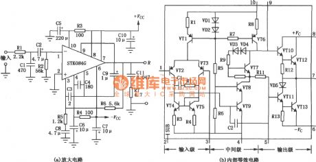
Figure (a) is a 50 W output power amplifier circuit composed of STK084G thick film power amplifier. STK084G is a thick-film integrated chip whose distortion rate is 0.01% in 20 kHz, 50 W. Its internal equivalent circuit is as shown in figure (b) .The input stage is a current mirror circuit composed of VT4 and VT5, which will transform the differential motion output to single-ended output to get a larger gain. VT8 uses ground connection to reduce the influence of Miller effect on its high frequency characteristics. VT1 and VT6 are constant current offset circuits,and they can restrain the influence of power change on the circuit. VT7 is used to output transistor offset. (View)
View full Circuit Diagram | Comments | Reading(1918)
The TV remote controller 21
Published:2011/6/14 2:51:00 Author:TaoXi | Keyword: TV, remote controller
TV remote controller 21
(View)
View full Circuit Diagram | Comments | Reading(754)
56~512kHz High-frequency Oscillator Circuit
Published:2011/6/30 4:17:00 Author:Joyce | Keyword: 56~512kHz, High-frequency , Oscillator
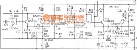
As shown in the figure is 56 ~ 512 kHz high-frequency oscillator circuit. It consists of high frequency oscillators and an alarm circuit.
1. The technique data:
(1) Frequency range: 56 ~ 512 kHz;
(2) output level: + 5.5± 1dB;
(3) frequency accuracy: no more than ± 20Hz;
(4) Alarm signal: when it stops oscillating, the alarm will light send out an alarm call.
(5) working temperature: it can guarantee index between 0 to + 45 ℃, and work reliably between - 10 to 0 ℃ and + 45 to + 50 ℃
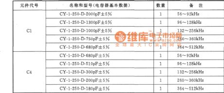
Choice of components :
audion VTl~VT4:3DG101C、β=65 ~ 85, VT5 ~ VT6:3DG1308, β= 85 ~ 115. Quartz crystal SJT: 101 quartz crystal with foot stand t namely GZC7 - F. Choices for capacitor C1 and C4 are shown in the table attached.
(View)
View full Circuit Diagram | Comments | Reading(863)
| Pages:1569/2234 At 2015611562156315641565156615671568156915701571157215731574157515761577157815791580Under 20 |
Circuit Categories
power supply circuit
Amplifier Circuit
Basic Circuit
LED and Light Circuit
Sensor Circuit
Signal Processing
Electrical Equipment Circuit
Control Circuit
Remote Control Circuit
A/D-D/A Converter Circuit
Audio Circuit
Measuring and Test Circuit
Communication Circuit
Computer-Related Circuit
555 Circuit
Automotive Circuit
Repairing Circuit