
Circuit Diagram
Index 1566
555 Power Supply Circuit that Changes from Single-supply to Dual-supply
Published:2011/7/5 0:11:00 Author:Zoey | Keyword: 555 Power Supply Circuit, Single-supply, Dual-supply
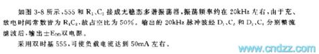
As shown in the figure3-8, the astable multi-vibrator consists of a 555, R1 and C2and its oscillation frequency is about 20kHz. As both the charge and discharge time constant are R1C2, the duty cycle is 50%. After the 20kHz pulse wave output have been filtered by D1, C3 and D2, C4 respectively, dual power supply ±EDDis output.
The application of dual time base helps load current to reach 50mAeven more.
(View)
View full Circuit Diagram | Comments | Reading(957)
555 Voltage-controlled Oscillator with an Adjustable Duty Cycle Period
Published:2011/7/5 0:10:00 Author:Zoey | Keyword: 555 Voltage-controlled Oscillator, Adjustable Duty Cycle Period
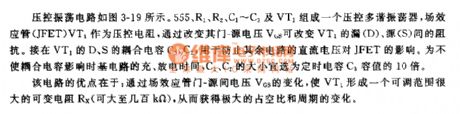
The voltage-controlled oscillation circuit has been shown in picture3-19. 555, R1, R2, C1~C3 and VT1 constitute a voltage-controlled multi-vibrator. As a voltage-controlled resistance, JFET can change the impedance between D/S. The coupling capacitance of D and S is used to eliminate the effect of other direct voltage on JFET. Timing capacitance of C1 and C2 should be selected as large as 10 times of C3.
Advantage of this circuit is that, an adjustable and changeable resistance can be formed by changing VGS, so as to obtain a large duty cycle and a changeable period.
(View)
View full Circuit Diagram | Comments | Reading(1153)
555 Low power consumption Monostable circuit
Published:2011/7/4 23:58:00 Author:Zoey | Keyword: Low power consumption, Monostable, circuit
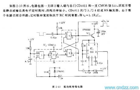
As shown in the picture 2-10, the circuit is composed of a four-two input terminal, a non-pin CD4011 and a CMOS-type 555, therefore, no matter in a stable state or in a state of outputting high-level pacification, it consumes little power. Pin 3 and pin 4 of CD4011 constitute an RS trigger. As the whole circuit is a closed loop, the time pulse width is determined by RC’s time constant, that is, td=1.1R1C1.
Picture 2-10 Low power-consuming Single stable circuit (View)
View full Circuit Diagram | Comments | Reading(1097)
Four Basic Circuits of 555 Monostable Trigger
Published:2011/7/5 Author:Zoey | Keyword: Basic Circuits, 555 Monostable Trigger
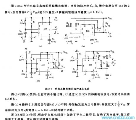
The circuit in the picture 2-8(a) is a typical monostable circuit. When external pulse is added to pin 2 of 555 via differential circuit C1 and R1, positive pulse will force 555 to set, temporarily stable pulse width that pin 3 outputs td is 1.1 RC.
Circuit in picture (b) has two output terminals. C discharges through R, and it takes longer for it to recover than that of (a).
Pin 2 and 6 in circuit of picture (c) joint a positive pulse, temporarily stable pulse is negative and the width is 1.1RC. They can output two circuits simultaneously.
Circuit in picture (d) has a faster charge ratio and higher work efficiency and can output two circuits simultaneously
(View)
View full Circuit Diagram | Comments | Reading(1647)
555 Linear Voltage/Frequency Converter circuit Four
Published:2011/7/4 23:57:00 Author:Zoey | Keyword: 555 Linear Voltage, Frequency Converter, circuit
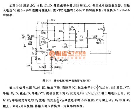
As shown in the picture5-37, IC1, R1, C1 and D1 constitute an integrator, 555, R2 and C2 constitute a monostable trigger, if input voltage Vi ranges from 0 to 10V, VFC circuit will have a conversion factor of 1kHz/V,which can be converted to frequency of 0~10kHz.
When signal voltage Vin is available, IC1 output will decline, andas soon asit declines to trigger level of IC2(<1/3VDD), 555 will set, VT2 will conduct,D2 and D3 will cease to work, D1 will conduct, VT1 will offer constant current to discharge to C1(If>Iin),output voltage on IC1 output terminal will rise. Then, monostable time capacitor C2 charges, when capacitance reaches to 2/3 VDD threshold level, 555 will reset, VT2 will cease to work, D2 and D3 will conduct, and D1 will cease to work. Therefore, move in cycles, voltage input is converted to oscillation that has various frequencies.
(View)
View full Circuit Diagram | Comments | Reading(1120)
The Bora phone electric control unit, aerial, microphone circuit
Published:2011/7/10 10:44:00 Author:Seven | Keyword: Bora, electric control unit, microphone
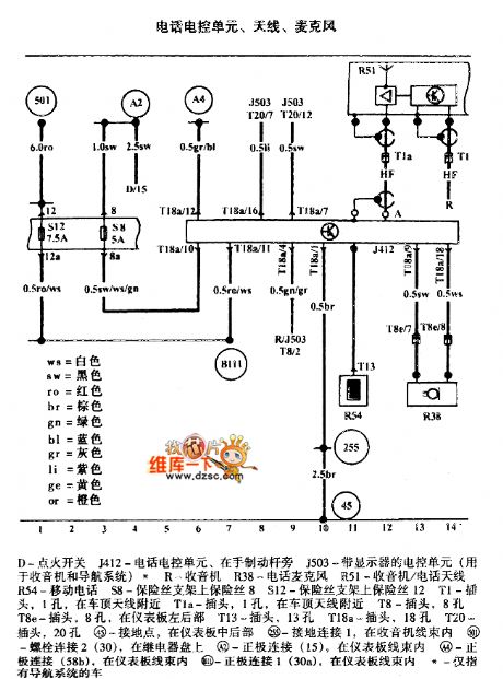
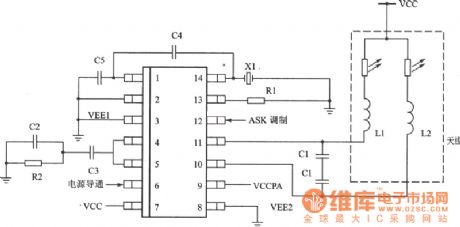
The Bora phone electric control unit, aerial, microphone circuit is shown as above.
D-igniting switch J412-phone control unit, at the side of the brake J503-the control unit with the display(used in radios and guided system) R-radio R38-phone microphone R51-radio/phone aerial R54-cell phone S8-fuse on the holder 8 S12-fuse on the holder 12 T1-plug, 1 hole, near the car ceiling aerial T1a-plug, 1 hole, near the car ceiling aerial T8-plug, 8 holes T8e-plug, 8 holes, in the rear part of the instrument T13-plug, 13 holes T18a-plug, 18 holes T20-plug, 20 holes (View)
View full Circuit Diagram | Comments | Reading(710)
Intelligent Single Pendulum Cycle Tester (89C2051, CD40106) Circuit Diagram
Published:2011/7/7 8:26:00 Author:Vicky | Keyword: Intelligent Single Pendulum Cycle Tester
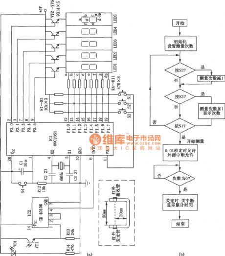
Intelligent single pendulum cycle tester circuit is shown in the picture. It is used in experiment of testing the cycle of single pendulum. The circuit is of high testing accuracy to centisecond. It can be done without human work of counting and timing. Therefore it only needs settings of the testing numbers. (View)
View full Circuit Diagram | Comments | Reading(1993)
ASK/FM 433/315MHz Emitter Circuit Diagram
Published:2011/7/10 6:05:00 Author:Vicky | Keyword: ASK/FM 433/315MHz Emitter
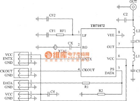
TH71072 applied circuit
TH71072 is a monolithic emitter chip which reaches standards of EN 300 220 and the analogs. It is available for keyless entering system, remote control/remote measuring system, data communication sysytem and security sysetem etc.
Main technical features are as follows:
·Work frequency range: 310~440 MHz;
·ASK modulation mode;
·ASK is conducted by interior power amplifier/gained by closing keying
·FM which makes use ofvariode which is connected externally
·Voltage of power supply: 2.2~5.5 V;
·Work current: 4.8~11.5 mA;
·Output power: -151~-1 dBm. (View)
View full Circuit Diagram | Comments | Reading(940)
ASK 320~290MHz Emitter Circuit Diagram
Published:2011/7/7 8:26:00 Author:Vicky | Keyword: ASK 320~290MHz Emitter
KESTX02 is a monolithic ASK emitter chip which meets therequirment of the basic power of FCC part l5 and harmonic suppression and is suitable for application of underpower wireless.
Main technical features are listed as follows:
·Operating frequency: 290~320 MHz;
·Complete integration of VC0, PLL and power amplifier;
·Low dissipation of current and improve of battery usage duration;
·Voltage of power supply: 3.5~6.5 V;
·Regulation of output power;
·Maximum work current: l2 mA, low power mode current: 0.7μA;
·Cheap exterior fittings.
Applied circuit of KESTX02
(View)
View full Circuit Diagram | Comments | Reading(773)
Current-Flowing-Direction Demonstrator Circuit Diagram
Published:2011/7/7 8:27:00 Author:Vicky | Keyword: Current-Flowing-Direction Demonstrator
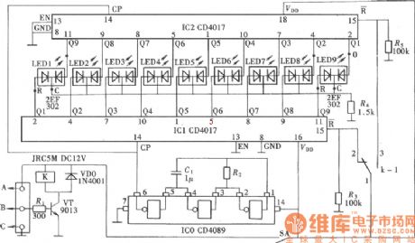
The circuit in the first picture adopts a transistor VT as input signal amplifier. VT is also used to drive a relay K. It drives the reset mode of pulse output circuit IC1& IC2’s reset end R by the changing of the relay’s contact, and thereby changes the lightening state of two-color luminous diodes to indicate the different flowing direction of the current.
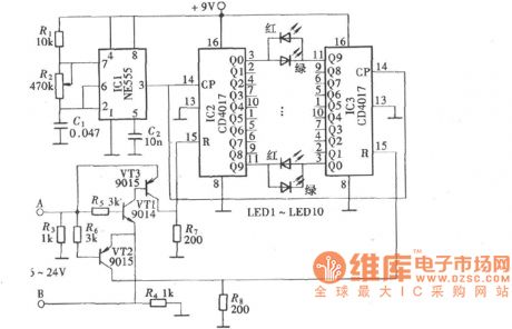
The second picture is an analog demonstrating conducted by a little instrument made of CMOS digital circuit. The circuit used decimal counter/pulse distributor CD4017, together with two-color luminous diode (the colors are red and green) to constitute a analog current-flowing-direction demonstrator.
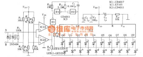
The circuit in the third picture uses work power voltage of 6V. If the work voltage needs to be changed, the resistance value of the resistance network should be re-calculated and the voltage of end R6 is 0.5V and must be lower than the voltage drop of VD2; the voltage of upper end of R5 is 0.5 and must be lower the voltage drop of VD1. (View)
View full Circuit Diagram | Comments | Reading(730)
wireless remote control doorbell circuit
Published:2011/7/9 9:42:00 Author:Lena | Keyword: wireless, remote control, doorbell
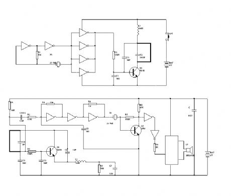
In the figure, these A、B inverter of hex inverter 406 and crystal X1 form a 32.768kHz signal generator, then inverters C, D, E, F are in parallel to modulate high frequency signal generator which is with Q1 as the core, then the generator outputs high frequency modulated wave, Q1 etc elements in figure 2 form a super regeneration receiving circuit, the circuit receives high frequency signal sent from emitter and modulates it to a 32.768kHz signal. The signal is amplified and shaped through C4, R3 and inverter A, B, C, then is filtered via crystal X1, Q2 trigger ding-dong music film to send out doorbell “ding-hu”.
(View)
View full Circuit Diagram | Comments | Reading(2595)
wireless remote control electric fan speed governor
Published:2011/7/9 8:58:00 Author:Lena | Keyword: wireless, remote control, electric fan, speed governor
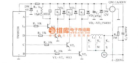
The speed regulating of desk-top electric fan usually adopts musical instrument keys mutual-lock switch controlling inductor spindle head on or off to realize. If we adopt remote control circuit, controlling relay and changing inductance spindle head access or alteration can obtain the same function as the musical instrument keys, and control speed regulating remotely. The remote control transmitting circuit of this electric fan speed governor adopts finished product component TWH9236, which is not shown in the figure. Remote control receiving circuit uses TWH 9238, and data output end A is idle.
(View)
View full Circuit Diagram | Comments | Reading(1417)
wireless remote control massor circuit
Published:2011/7/8 23:32:00 Author:Lena | Keyword: wireless, remote control, massor
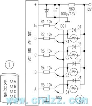
This remote control massor is used to knead waist, shoulder damage, and it has effectivity on health care and curing the injury. Because of small bulk, you can take with it anytime. Gently press a emitter key, the point can have abundant rubdown. Now introduce the manufacture method of this remote control massor, somebody interested in this can try it.
Figure 1 is a keychain multi-way wireless remote control emitter, and has A, B, C, D four keys.
(View)
View full Circuit Diagram | Comments | Reading(603)
SAAl293 (TV) single chip microprocessor
Published:2011/7/8 9:26:00 Author:Lena | Keyword: single chip, microprocessor
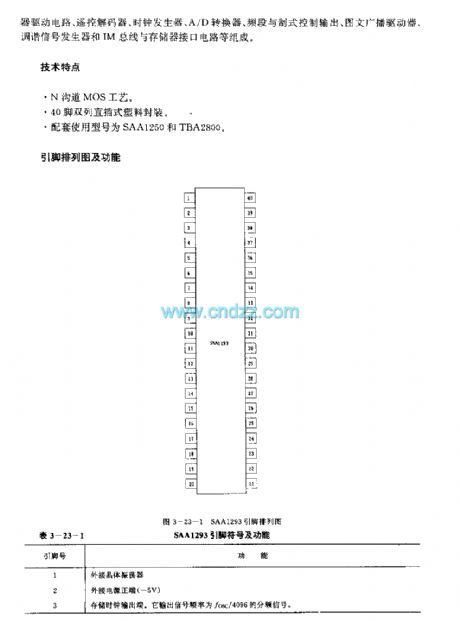
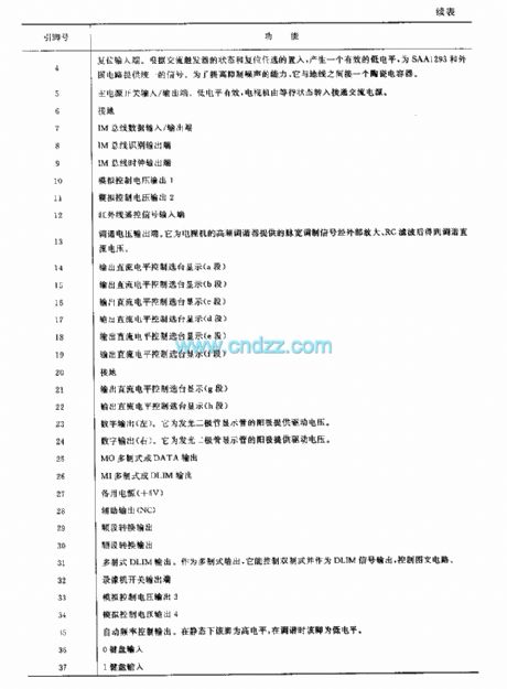
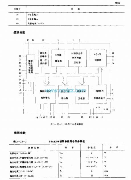
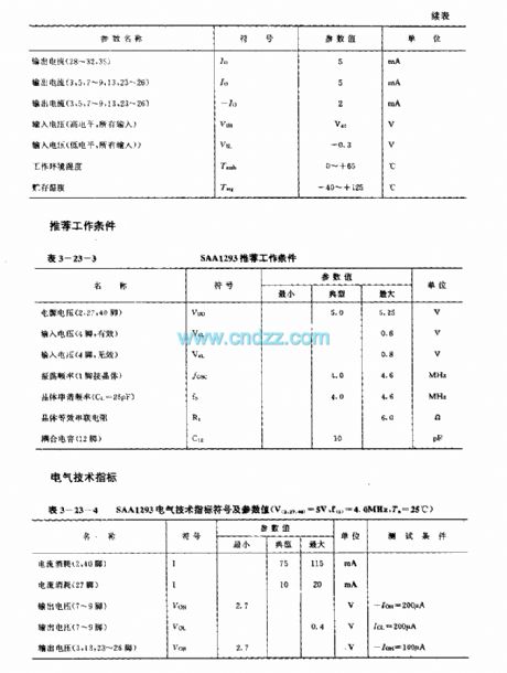
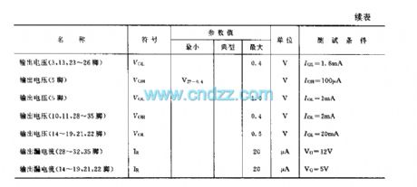
SAA1293 is a single chip microprocessor applied to high/middle TV remote control system. Internal circuit consists of keyboard input and display drive circuit, remote control decoder, clock generator, A/D converter, video and system control output, picture and text driver, coordination signal generator and IM bus line and register interface circuit etc.
Technology characteristicN-channel MOS technics40-pin dual-in-line plastic packageSupporting types are SAA1250 and TBA2800
(View)
View full Circuit Diagram | Comments | Reading(654)
BA8207K(Fan) infrared remote control receiving control circuit
Published:2011/6/13 22:05:00 Author:Lena | Keyword: infrared, remote control, receiving
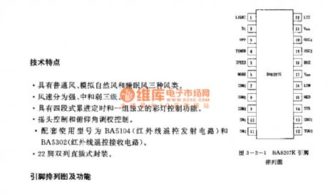
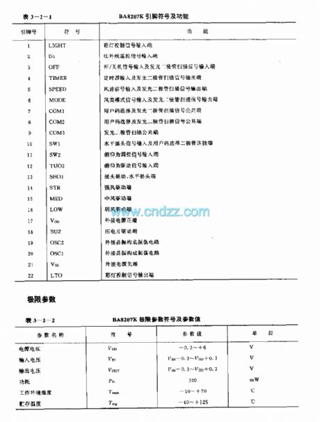
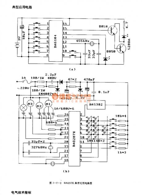
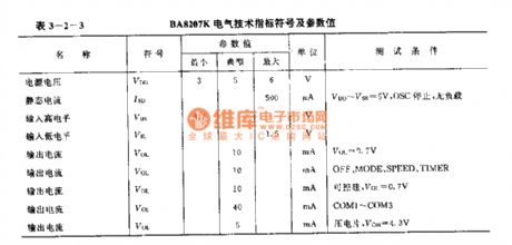
Technology characteristicThree sort: common wind, simulation natural wind and sleep wind.Wind speed is classified to strong, middling and weak.Four-flight progressive timing and a set of absolute color light control function.Pioting control and longitudinal attitude adjust control.Related types are BA5104(infrared remote control transmitting circuit)and BA5302(infrared remote control receiving circuit).22-pin dual-in-line package.
(View)
View full Circuit Diagram | Comments | Reading(739)
Gree KYTA-30B remote control electric fan circuit
Published:2011/7/8 19:36:00 Author:Lena | Keyword: remote control, electric fan
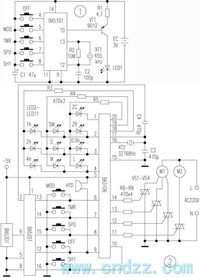
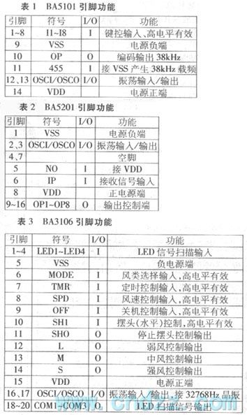
Gree KYTA-30B is a multi-function infrared electric fan, which is with a programmable control circuit BA3106 as the core, and coordinates with a pair of infrared remote control code/encoder BA5101/BA5201. It has the following features: strong, middle, weak wind speed control; common, nature, sleep wind class selection; sleep wind can be auto pre-set in 4 hours; 7.5 hours four-segment progressive timing; a set of independency electric shake function; correct input buzzer prompt and uses 32768Hz crystal oscillator as the time base.
(View)
View full Circuit Diagram | Comments | Reading(787)
adding computer control circuit for common fan
Published:2011/7/8 19:28:00 Author:Lena | Keyword: computer control, common fan
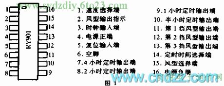

The popular “computer fan” or “electric programmable control fan” on the market, are mostly combinative production of integrated circuit controller and old-fashioned fan. This circuit uses a selling special integrated circuit RY901, refitting a common fan to a multifunction senior fan, suited for wireless hobbyist to make and refit.
The main feature of new type IC is: It brings together switch, timing, adjust speed and simulate nature wind, and has less periphery elements, simple circuit, simple facture.
(View)
View full Circuit Diagram | Comments | Reading(687)
TOSHIBA 2500XH pincushion correction circuit
Published:2011/7/8 20:09:00 Author:Lena | Keyword: pincushion correction
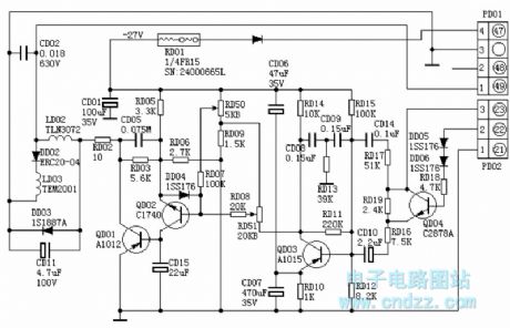
Circuits which are the same as TOSHIBA 2500XH pincushion correction circuits have the following types: TOSHIBA 2506XH, 2800XH, 2806XH etc.Field saw tooth wave voltage is sent to B pole of QD03 by (3) pin of PD02, RD17, CD 14, RD 16, RD19 and CD10. QD04 is a 50Hz/60Hz switch electronic on-off, when it is at 50Hz, QD04 is cut-off, when at 60 Hz, QD04 is conducted, then RD19 becomes a short circuit, the extent of saw tooth wave sent to QD03B pole is augment.
QD03 is a field parabolic wave voltage forming tube, at C pole, the tube outputs a sunken parabolic wave voltage, which is added to B pole of QD02 after accommodated amplitude by RD51, QD02 and QD01 are parabolic wave amplifier tube, RD50 is a row extent regulation potentiometer.
(View)
View full Circuit Diagram | Comments | Reading(923)
infrared remote control time-lapse lamp circuit
Published:2011/7/8 20:45:00 Author:Lena | Keyword: infrared, remote control, time-lapse lamp
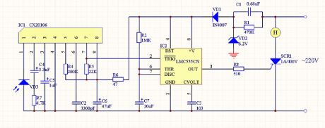
Infrared remote control time-lapse lampInfrared remote control time-lapse lamp is applied to casual situation in night. This illumination will not need to be turned off by remote controller, and will auto be turned off by set delayed circuit in internal circuit. Delayed time usually can be set as 1-2MIN, the operation can adopt infrared remote control emitter without modulation signal to realize.Circuit principle:This circuit can consist of infrared receiver, Uni-stable state delayed circuit and controlled silicon circuit.
(View)
View full Circuit Diagram | Comments | Reading(1037)
White LED Current Control Circuit of Charge-pump
Published:2011/6/28 5:26:00 Author:Michel | Keyword: White LED, Current Control, Circuit, Charge-pump
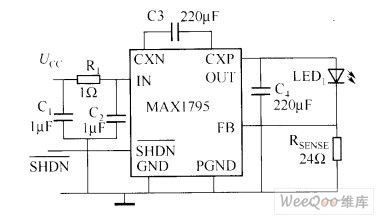
White LED Current Control Circuit of Charge-pump (View)
View full Circuit Diagram | Comments | Reading(911)
| Pages:1566/2234 At 2015611562156315641565156615671568156915701571157215731574157515761577157815791580Under 20 |
Circuit Categories
power supply circuit
Amplifier Circuit
Basic Circuit
LED and Light Circuit
Sensor Circuit
Signal Processing
Electrical Equipment Circuit
Control Circuit
Remote Control Circuit
A/D-D/A Converter Circuit
Audio Circuit
Measuring and Test Circuit
Communication Circuit
Computer-Related Circuit
555 Circuit
Automotive Circuit
Repairing Circuit