
Circuit Diagram
Index 1563
Cumulative Timer
Published:2011/7/4 10:20:00 Author:Felicity | Keyword: Cumulative Timer

work of the circuit
The circuit consists of resistor R1-R4, capacitor C, diode VD1-VD5, transistor V1, V2 and the crystal OSC BC. (It is showed in picture 8-144.)
Turn on the power switch of the electronic instrument and the 220V voltage is limited by R1 and R2 and rectified by VD1-VD4. It produces 2.07V DC voltage on C. The timing begins. When the power switch of the electronic instrument is turned off, the voltage on C disappears. The frequency division circuit stops vibrating. But the frequency division circuit remains in the condition. When you turn on S next time, it begins to time again. (View)
View full Circuit Diagram | Comments | Reading(653)
Ultrasonic Therapeutic Equipment (the 1st)
Published:2011/7/7 9:56:00 Author:Felicity | Keyword: Ultrasonic Therapeutic Equipment, the 1st
Work of the circuit
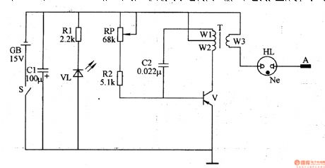
The circuit consists of power circuit, ultrasonic vibration circuit and outputting circuit. (It showed in picture 9-17.)
Turn on the power switch S and the ultrasonic vibration circuit works. Pulse voltage of 5KV is produced on winding W3 of T. when you use the instrument, use pole A to touch the tissue with focus nidus. The tissue produces sight massage and proper heating to reduce inflammation and ease pain.
Change the value of RP to change the vibration frequency of the ultrasonic therapeutic equipment. (View)
View full Circuit Diagram | Comments | Reading(787)
Magnetism pulse Therapeutic Equipment (the 2nd)
Published:2011/7/7 9:57:00 Author:Felicity | Keyword: Magnetism pulse Therapeutic Equipment, the 2nd
Work of the circuit
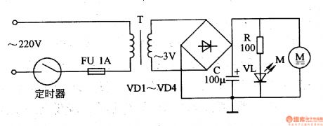
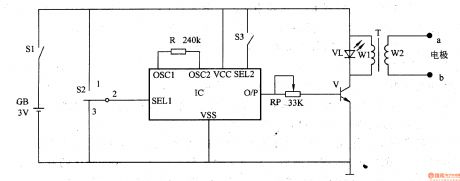
The circuit consists of timer, fusible cut-out FU, mains transformer T, rectifier diodeVD1-VD4, filtering capacitor C, limiting resistor R, power indicating diode VL and motor M. (It is showed in picture 9-16.)
Set the regular time and turn on the power. The 220V AC voltage is adjusted and produces 3v voltage. The DC voltage is M’s working voltage and lightens VL.
When M is working, permanent magnetisms of driver 4 is revolving. It produces moving revolving magnetic field. When you use the equipment, you need to use it to point the treating position.
When the regular time is reached, the switch withen the timer is cut-off. The power of the whole circuit is cut-off and VL stops shines. (View)
View full Circuit Diagram | Comments | Reading(550)
Voltage Regulator (the 1st)
Published:2011/7/7 9:46:00 Author:Felicity | Keyword: Voltage Regulator, the 1st
Work of the circuit
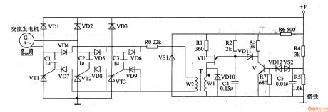
The circuit consists of sampling detection control circuit and relaxation oscillator circuit. (It is showed in picture 7-141.)
Sampling detection control circuit consists of resistors R3-R7, capacitor C5, voltage regulator diode VSI, VS2, diodes and transistors V VDl2.
Relaxation oscillator circuit consists of resistors Rl, R2, capacitor C4, diode VDlO, single-junction transistors VU and isolation transformer T.
Three-phase alternating generator exports pulsating DC voltage +V. The voltage is adjusted by R4 and R5 and added to the negative pole of VS2. The voltage separates into two parts. One is limited by R6 and works as the working voltage of sampling detection control circuit and relaxation oscillator circuit. C4 is charging by R2. When the pressure over C4 reaches the highest value of VU, VU is transmitted. At this time C4 is discharging through VU. When the voltage over C4 is lower than a certain value, C4 begins to charge and discharge. The process repeats and the relaxation oscillator circuit is under the condition of oscillating. The rectifier exports current. (View)
View full Circuit Diagram | Comments | Reading(521)
Electrical Pulse Therapeutic Apparatus (the 12th)
Published:2011/7/7 9:43:00 Author:Felicity | Keyword: Electrical Pulse Therapeutic Apparatus, the 12th
Work of the circuit
The circuit consists of oscillation frequency divider, triangle wave forming circuit, pulse amplifier and booster circuit. (It is showed in the picture 9-12.)
Oscillation frequency divider consists of internal oscillator divider circuit timing IC and capacitor Cl, resistor RlO, Rll, potentiometer RPl.
Triangle wave forming circuit consists of IC and resistors Rl-R8.
Pulse amplifier consists of switch Sl, resistor R9, Rl2, capacitor C2, transistor Vl and working mode selection switch S2.
Booster circuit consists of output amplifier tube V2, step-up transformer T and potentiometer RP.
(View)
View full Circuit Diagram | Comments | Reading(607)
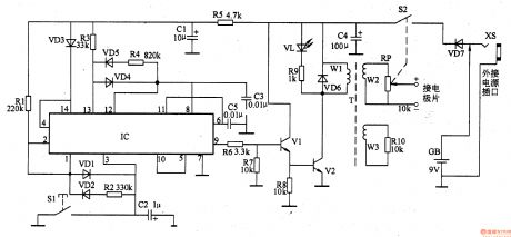
Electrical Pulse Therapeutic Apparatus (the 11th)
Published:2011/7/7 9:44:00 Author:Felicity | Keyword: Electrical Pulse Therapeutic Apparatus, the 11th
Work of the circuit
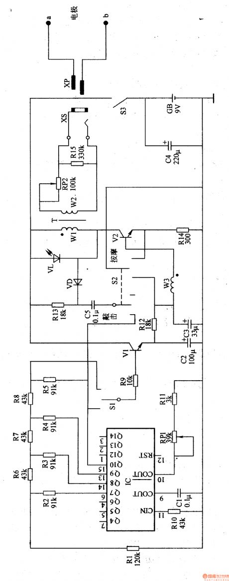
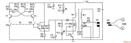
The circuit consists of power supply circuit, a square wave pulse oscillator, control circuit, pulse peak oscillator and pulse voltage output circuit. (It is showed in the picture 9-11.)
Power supply circuit consists of Source switch Sl, battery GB, filter capacitor C3, current limiting resistor Rll and the power indicator LED VL1.
Square wave pulse oscillator consists of Resistors Rl-R4, capacitor Cl, C2 and transistors Vl, V2.
Control circuit consists of Control switch S2 (S2a, S2b), the transistor V3 and resistors R5-R7.
Pulse peak oscillator consists of resistors R5-R8, capacitor C4, C5, LED V ashamed, diode VD, transistors V4 and pulse transformer T, winding Wl, W2.
Pulse voltage output circuit consists of T’s winding W3, resistors R9, RlO, potentiometer RP, output jack XS, XP and plug electrodes a, b. (View)
View full Circuit Diagram | Comments | Reading(632)
Electrical Pulse Therapeutic Apparatus (the 9th)
Published:2011/7/7 9:44:00 Author:Felicity | Keyword: Electrical Pulse Therapeutic Apparatus, the 9th
Work of the circuit
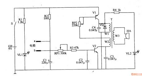
The circuit consists of sound generator and the electrical pulse generator circuit. (It is showed in the picture 9-9.)
Sound generator circuit consists of sound IC IC, resistor R and the control switch S2, S3 components. Electrical pulse generating circuit by the potentiometer RP, transistor V, light-emitting diode VL, step-up transformer T and the electrode a, b.
Change the value of RP to change the Electrical pulse’s stimulus intensity.
You can choose four kinds of sound sources through S2 and S3. They have different effects of electrical stimulation. (View)
View full Circuit Diagram | Comments | Reading(658)
Electrical Pulse Therapeutic Apparatus (the 8th)
Published:2011/7/7 9:45:00 Author:Felicity | Keyword: Electrical Pulse Therapeutic Apparatus, the 8th
Work of the circuit
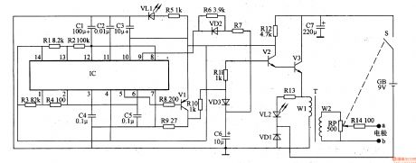
The circuit consists of power supply circuit, self-excited oscillator and electrical pulse generator circuit. (It is showed in the picture 9-8.)
Self-excited oscillator consists of Dual time-base integrated circuit IC, resistors Rl-R4 and capacitors Cl-C5.
Electrical pulse generator circuit consists of transistor Vl-V3, resistors R6-R14, capacitor C6, diode VDl-VD3, light-emitting diode VL2, pulse transformer T, potentiometer RP and electrodes a, b.
Change the value of RP to change the Electrical pulse’s stimulus intensity. (View)
View full Circuit Diagram | Comments | Reading(626)
Electronic Points Probing Instrument (the 2nd)
Published:2011/7/7 9:57:00 Author:Felicity | Keyword: Electronic Points Probing Instrument, the 2nd
Work of the circuit
The circuit consists of probing circuit, OSC, acousto-optic indicating circuit and power circuit. (It is showed in picture 9-39.)
Turn on the switch S. put one pole in the tester’s hand. And use the other one to probe the acupoint near the ears. The 9V voltage of GB makes the OSC work. It also drives HA to make sound. If the electric resistance of the acupoint is small, the frequency of the OSC is higher. The tone of the sound which is made by HA is higher. It works on the other way.
(View)
View full Circuit Diagram | Comments | Reading(564)
Lectronic Weight Instrument (the 1st)
Published:2011/7/7 9:59:00 Author:Felicity | Keyword: lectronic Weight Instrument, the 1st)
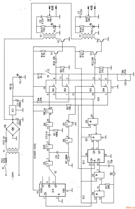
Work of the circuit
The circuit consists of power circuit, OSC, pulse-width controlling circuit, pulse group space controlling circuit, paraphase controlling circuit, outputting controlling circuit and driving controlling circuit. (It is showed in picture 9-36.)
Turn on the switch S1 and the 220V DC voltage produces 9V DC voltage. The voltage separates into two parts. One is supplied to outputting circuit. And the other one is stabilized to 5v to work for IC2-IC6. When the OSC is working, oscillation of low frequency is produced from pin 3 of IC3. The internal stimulated switch SO1 and SO3 is turned on with hiatus. The high pressure pulse string is added on the body through pole a, b, c and d.
(View)
View full Circuit Diagram | Comments | Reading(566)
Electronic Pain Relieving Instrument (the 1st)
Published:2011/7/7 10:00:00 Author:Felicity | Keyword: Electronic Pain Relieving Instrument, the 1st
Work of the circuit
The circuit consists of pulse making circuit, controlling circuit and voltage rising circuit. (It is showed in picture 9-31.)
Turn on switch S1 and capacitor is short. Pulse maker makes continues pulse. Then S1 is turned off and the pulse maker makes intermitted pulse.
IC1’s pin 9 outputs pulse signal. The signal is amplified by V1 and V2 and becomes electronic pulse on W2. The electronic pulse stimulates the sexine nurse of skin and makes the cerebrum center make pain relieving hormone. (View)
View full Circuit Diagram | Comments | Reading(566)
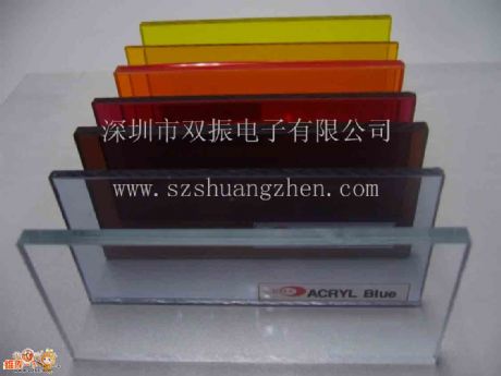
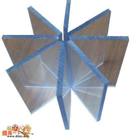
South Korea Imported Anti-static PVC Board of Shuangzhen Supply
Published:2011/6/25 4:31:00 Author:Michel | Keyword: Shuangzhen Supply, South Korea, Imported, Anti-static, PVC Board
Shuangzhen supplies South Korea imported anti-static PVC board.Shenzhen Shuangzhen Electronic Co., Ltd is found in Feb. 2007 which has office and warehouses. We are specialied in providing anti-static organic glasses.We devote to providing high-quality industrial products to meet the special needs of high-tech times industry and provide good after-sales service.
Shenzhen/Suzhou/Shanghai/Dalian has South Korea imported anti-static PVC board in stocks.The surface resistance is10^6~10^8Ω with excellent antistatic properties.The appearance isbeautiful and the surface is very smooth.Antistatic properties are not easily affected by temperature and humidity. (View)
View full Circuit Diagram | Comments | Reading(710)
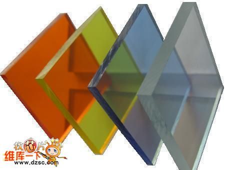
Static-free Acrylate Sheet Stocks of Shuangzhen Electronic Shenzhen/Shanghai/Dalian
Published:2011/6/24 12:30:00 Author:Michel | Keyword: Static-free, Acrylate Sheet, Stocks, Shuangzhen Electronic, Shenzhen, Shanghai, Dalian
Shuangzhen Electronic Shenzhen/Shanghai/Dalian supplies static-free acrylate sheet stocks.Shenzhen Shuangzhen Electronic Co., Ltd is found in Feb. 2007 which has office and warehouses. We are specialied in providing anti-static organic glasses.We devote to providing high-quality industrial products to meet the special needs of high-tech times industry and provide good after-sales service.
Feature
The surface resistance is 10^6~1068Ω with the stable antistatic properties.
Excellent surface hardness and high chemical solvents erosion performance . (View)
View full Circuit Diagram | Comments | Reading(555)
South Korea Imported Anti-static or Shock Resistant PC Board of Shaungzhen Supply
Published:2011/6/24 12:18:00 Author:Michel | Keyword: Shaungzhen Supply, South Korea Imported, Anti-static, Shock Resistant, PC Board
Shuangzhen supplies south Korea imported anti-static or shock resistant PC board .Shenzhen Shuangzhen Electronic Co., Ltd is found in Feb. 2007 which has office and warehouses. We are specialied in providing anti-static organic glasses.We devote to providing high-quality industrial products to meet the special needs of high-tech times industry and provide good after-sales service.
Shenzhen/Shanghai/suzhou/dalianhas anti-static PC board in stock.
Feature
The surface resistance is 10^6~10^8Ω/ with excellent antistatic properties. (View)
View full Circuit Diagram | Comments | Reading(660)
Deep Discussion: Clamp Type Current Transformer Circuit
Published:2011/7/1 18:47:00 Author:Michel | Keyword: Deep Discussion, Clamp Type, Current Transformer, Circuit
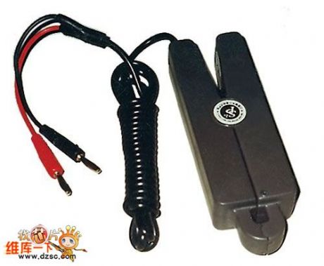
SP series clamp type current transformer belongs to precision current transformer category and it is a high precision AC current converter,for example,Praise verification tester for electric power, multi-function watt-hour meter, power analyzer, oscilloscope, digital multimeter , cable faults, double clamp detector type earthing resistance tester, double clamp type phase volt-ampere table, etc.In the constant state of being measured open road, kinds of electric parameters are measured and compared.
The series products production and manufacturing strictly abide by GB1208-1997 Current Transformer and JJG31-1994 Measuring Current Transformer Verification Regulation. (View)
View full Circuit Diagram | Comments | Reading(608)
Single-end Flyback DC-DC Converter Circuit
Published:2011/6/24 0:54:00 Author:Michel | Keyword: Single-end, Flyback, DC-DC, Converter Circuit
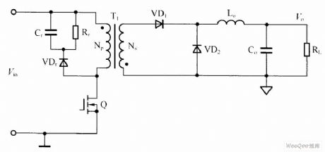
The single-end flyback DC-DC converter circuit is shown as above.Among them,transformer acts as isolation,transmission,energy storage.That's to say,Np stores energy when switch tube Q turns on and Np release energy to Ns when switch tube Q shuts off.A low-pass filter composed of a inductor Lo and capacitance Co is added to the output side,transformer primary level Cr, Rr and VDr constitute RCD leakage peak absorbing circuit.In output loop,a VD1 rectifier diode is needed.If the transformer uses the magnetic core with wind gap,the copper loss is big and temperature rising is relatively higher and its output ripple voltage is larger.But its advantage is that the circuit structure is simple and is suitable for less than 200W power supply. (View)
View full Circuit Diagram | Comments | Reading(1023)
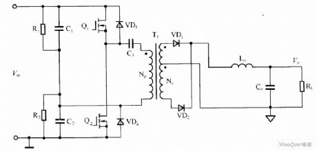
Double-tube Forward DC-DC Converter Circuit
Published:2011/6/24 1:15:00 Author:Michel | Keyword: Double-tube, Forward, DC-DC, Converter Circuit
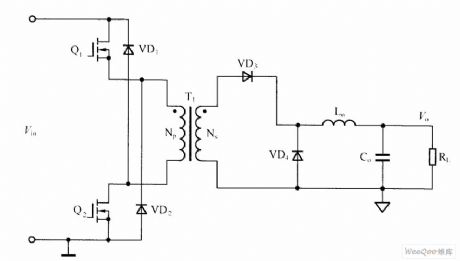
Double-tube forward DC-DC converter circuit is shown as above.Among them,transformer T1 acts as isolation and transformation and and inductance Lo(flow current inductance) is added to output port which acts as energy storage and transmission.The transfomer primary level does not need reset winding because both VD1 and VD2 conduction limit the voltage which two regulation tubes bear when they are turned off.In output loop ,a rectifier diode VD3 and a free-wheeling diode VD4 (VD3, VD4 had better choose the rectifier diode with short recovery time )are needed.Output filter capacitance Co should chooselarge capacity capacitance with low equivalent resistance to reduce the ripple voltage(other topology structure also require like this).
Picture:Double-tube Forward DC-DC Converter Circuit (View)
View full Circuit Diagram | Comments | Reading(1124)
Half Bridge DC/DC Converter Circuit
Published:2011/6/24 1:36:00 Author:Michel | Keyword: Half Bridge, DC/DC, Converter Circuit
The half bridge DC/DC converter circuit is shown as above.Among them,transformer acts as isolation and transfering energy. Np winding bears half input voltage and vice edge winding voltage make VD1 conducts when switch tube Q1 conducts and vice versa.In the output, VD1, VD2 Lo and Co constitutes rectifier filter circuit. (View)
View full Circuit Diagram | Comments | Reading(5487)
Full Bridge DC/DC Converter Circuit
Published:2011/6/24 1:52:00 Author:Michel | Keyword: Full Bridge, DC/DC, Converter Circuit
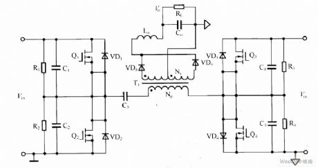
The full bridge DC/DC converter circuit is shown as above.Full bridge DC/DC converter are mainly used in high-power power supply and it has following features.First,transformer utilization rate is rather high, unloaded energy can give feedback to the power grid, the power supply has high efficiency.Second,there is no steady-state error at stable state and it responses quickly in dynamic condition and the system is stable and it has high anti-interference ability to high frequency.
Picture:Full Bridge DC/DC Converter Circuit (View)
View full Circuit Diagram | Comments | Reading(1490)
MX1576 Charge-pump Drving White LED Circuit
Published:2011/6/23 23:05:00 Author:Michel | Keyword: Charge-pump, Drving, White LED Circuit
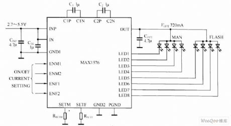
MAX1516 charge-pump can drive up to 8 white LED and it has constant current adjustment function, in order to achieve unified light intensity. The MAX1516 charge-pump can drive every group LED with 30mA which is used in blacklight.Flash group LED (LED5 ~ LED8) is the solely controlled, and they are able to use 100 mA current drive each LED ( 400 mA in total) .Through the use of adaptive 1 x, 1.5 x, 2 x mode charge-pump and current regulator of ultra low voltage difference, MAX1576 can achieve high efficiency in a lithiumion battery voltage range.Because fixed switching frequency is 1 MHz, low EMI and low input ripple. can be ensured by only using very little external components and regulation scheme optimization. (View)
View full Circuit Diagram | Comments | Reading(621)
| Pages:1563/2234 At 2015611562156315641565156615671568156915701571157215731574157515761577157815791580Under 20 |
Circuit Categories
power supply circuit
Amplifier Circuit
Basic Circuit
LED and Light Circuit
Sensor Circuit
Signal Processing
Electrical Equipment Circuit
Control Circuit
Remote Control Circuit
A/D-D/A Converter Circuit
Audio Circuit
Measuring and Test Circuit
Communication Circuit
Computer-Related Circuit
555 Circuit
Automotive Circuit
Repairing Circuit