
Circuit Diagram
Index 1570
Lithium battery charging circuit with the temperature monitoring and charge status indicating functions
Published:2011/7/8 5:55:00 Author:TaoXi | Keyword: Lithium battery, charging circuit, temperature monitoring, charge status, indicating, functions
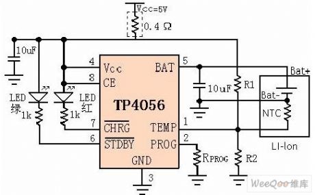
The TP4056 is designed as one kind of single lithium-ion battery which uses the constant current/constant voltage linear charger. The SOP8/MSOP8 package with the radiator in the bottom and less external components number make the TP4056 become the ideal choice of the portable applications. The TP4056 is suitable for the operating of the USB power and the adapter power. Because this device uses the internal PMOSFET architecture and the anti-reverse-charging circuit, so there is no need to use the external isolation diode. The heat feedback can automaticly adjust the charging current to limit the chip temperature in the high power operation or high environment temperature conditions.
(View)
View full Circuit Diagram | Comments | Reading(4147)
Auto Flash Alarm
Published:2011/7/10 23:50:00 Author:Felicity | Keyword: Auto Flash, Alarm
Work of the circuit
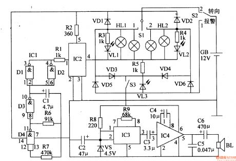
The circuit consists of low-frequency oscillator, the electronic switch circuit, control circuit, photoelectric display circuit and music alarm circuit. (It is showed in picture 7-113.)
Low-frequency oscillator consists of IC lCl (Dl-D4) internal NAND gate circuit D3, D4 and external RC components.
Control circuit consists of ICl internal non-gate Dl and D2. It is used to control high-power electronic switch IC lC2.
Photoelectric display circuit consists of diode VDl-VD6, LED VLl-VL3 (installed in the steering switch) and the resistors R3-R5.
Music alarm circuit consists of music integrated circuit IC3, audio amplifier integrated circuit IC4, speaker BL and related peripheral components. (View)
View full Circuit Diagram | Comments | Reading(1670)
Relay circuit directly drived by the analog switch chip
Published:2011/7/8 5:55:00 Author:TaoXi | Keyword: Relay circuit, analog switch chip
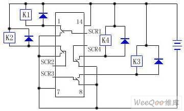
The CD4066 is designed as one kind of quad two-way analog switch, the integrated blocks SCR1~SCR4 are the control ports. When the SCR1 is connected with the high level, the pin-1 and pin-2 of the integrated block conduct, the +12V voltage adds to the K1 to connect the pin-1 and pin-2 with the negative electrode of the power supply, so K1 closes; otherwise when the SCR1 is connected with the low level, the pin-1 and pin-2 of the integrated block are the open circuits, K1 releases, the states of the SCR2~SCR4 are the same as the state of the SCR1 when SCR2~SCR4 are connected with the high or low level.
In this circuit, both ends of the relay coil are connected with the diode to protect the integrated circuit itself.
(View)
View full Circuit Diagram | Comments | Reading(712)
Intermittent Controller (the 1st)
Published:2011/7/10 22:42:00 Author:Felicity | Keyword: Intermittent Controller,

Work of the circuit
The circuit consists of power circuit, timer and control implementation circuit. (It is showed in picture 8-96.)
Power circuit consists of Capacitors C2-C4, resistors R3-R5, bridge rectifier, UR, voltage regulator diode VS and power indicator LED VL.
Timer circuit consists of counter / divider integrated circuit IC, capacitor Cl, diode VD2-VD4 and resistors Rl, R2, R6. Clock oscillator circuit consists of Rl、R2、Cland IC internal circuit.
Control implementation circuit consists of transistor V, resistor R7, diode VDl, relay K and AC contactor KM. (View)
View full Circuit Diagram | Comments | Reading(807)
Intermittent Controller (the 2nd)
Published:2011/7/10 22:43:00 Author:Felicity | Keyword: Intermittent Controller,
Work of the circuit
The circuit consists of power circuit, timing control circuit and control implementation circuit. (It is showed in picture 8-97.)
Power circuit consists of fuse FU, power transformer T, bridge rectifier, UR, filter capacitor C3, three-terminal voltage regulator integrated circuit IC2, current limiting resistor Rl and the power indicator LED VLl.
Timing control circuit consists of time-base integrated circuit ICl, potentiometer RPl and R Robinson, resistor R2, work instructions LED VL2 and capacitors Cl, C2.
Control implementation circuit consists of relay K, AC contactor KM and diode VD. (View)
View full Circuit Diagram | Comments | Reading(876)
24V power supply CRT high voltage power generating circuit
Published:2011/7/8 5:54:00 Author:TaoXi | Keyword: 24V, power supply, CRT, high voltage, power generating
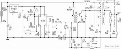
Some cameras' CRT uses the 11.4cm flat CRT as the display unit, the anode voltage of the high-voltage component is +20kv, the focusing electrode voltage is +3.2KV, the accelerating electrode voltage is +1000V, the power supply of the high-voltage component is 24V DC. The basic principle: the pulse generator is composed of the NE555, the potential regulator VR2 can make it produce the 20KHz pulse, the potentiometer VR1 adjusts the pulse width. The TR1 is the driver stage, the pulse transformer T1 uses the reverse polarity incentive. The high voltage protection circuit is composed of the D3, D9, VR3, R7 and the D4, R6, TR3. The VR2 can be used to adjust the frequency, you can adjust the high voltage by adjusting VR2.
(View)
View full Circuit Diagram | Comments | Reading(1791)
Modem and PC interface circuit
Published:2011/7/8 5:52:00 Author:TaoXi | Keyword: Modem, PC, interface circuit
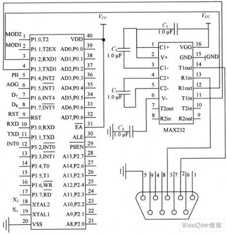
The Modem and PC interface is the interface circuit of the Modem's single-chip microcomputer W77E58 and the PC, the W77E58 supports the TTL level, and the microcomputer serial communication interface RS 232C supports the EIA level, so you need to design the level conversion circuit when you are realizing the serial communication between them to meet their needs.
The level conversion circuit is the interface circuit of the command center modem and the microcomputer, it is also a part of the wireless data transmission system hardware circuit (command center).
(View)
View full Circuit Diagram | Comments | Reading(934)
Seat Belt Language Reminder
Published:2011/7/10 22:46:00 Author:Felicity | Keyword: Seat Belt, Language Reminder
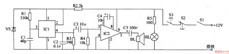
Work of the circuit
The circuit consists of Power regulator / indicator circuit, control circuit, the language generator and audio amplifier output circuit. (It is showed in picture 7-114.)
Power regulator / indicator circuit consists of current limiting resistors R2, R5, zener diode VS and LED HL.
Control circuit consists of Ignition switch S1, turn-on switch S3 and turn-off switch S2.
The language generator consists of language IC lCl, resistors Rl, R3 and capacitor Cl, C2.
Audio amplifier output circuit consists of audio power amplifier IC lC2, resistor R4, capacitor C4, C5 and speaker BL. (View)
View full Circuit Diagram | Comments | Reading(1447)
The circuit of the electric transducer
Published:2011/7/8 5:52:00 Author:TaoXi | Keyword: electric transducer
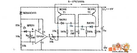
The circuit of the electric transducer is as shown in the figure:
(View)
View full Circuit Diagram | Comments | Reading(684)
Intermittent Controller (the 3rd)
Published:2011/7/10 22:45:00 Author:Felicity | Keyword: Intermittent Controller,
Work of the circuit
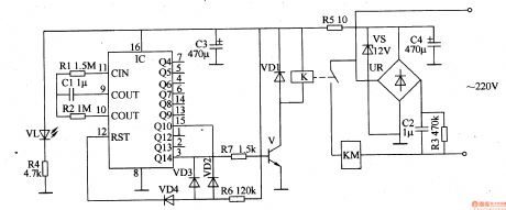
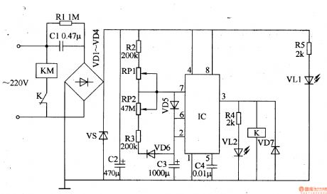
The circuit consists of power circuit, timing control circuit and control implementation circuit. (It is showed in picture 8-98.)
Power circuit consists of Buck capacitor Cl, resistors Rl, R5, rectifier diode VDl-VD4, voltage regulator diode VS, power indicator light-emitting diode VL1and filter capacitor C2.
Timing control circuit consists of time-base integrated circuit IC, resistors R2-R4, capacitors C3, C4, potentiometer RPl, RP2, diode VD5, VD6 and light-emitting diode VL2.
Control implementation circuit consists of diode VD7, relay K and AC contactor KM. (View)
View full Circuit Diagram | Comments | Reading(835)
Sleepiness Reminder
Published:2011/7/10 23:41:00 Author:Felicity | Keyword: Sleepiness Reminder
Work of the circuit
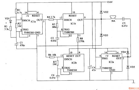
The circuit consists of astable oscillator, lkHz oscillator, 3Hz ultra-low-frequency oscillator and the audio output circuit. (It is showed in picture 7-117.)
Astable oscillator consists of dual time-base integrated circuit ICla, resistors Rl-R3, diodes VDl and capacitors CI.
lkHz oscillator consists of IClb, resistors R4, R5 and capacitor C2.
3Hz ultra-low-frequency oscillator consists of dual time-base integrated circuit IC2b, resistors R6, R7 and capacitor C4.
The audio output circuit consists of IC2a, diode VD2-VD5, capacitor C5 and buzzer HA. (View)
View full Circuit Diagram | Comments | Reading(708)
Radio control explosive device which is composed of the S%26P27A/S%26P27B
Published:2011/6/14 3:00:00 Author:TaoXi | Keyword: Radio control, explosive device
In the exploitation of mines and the blasting of rock material, the radio control explosive method is more flexibility, reliability and economy than the method of wire control. The radio control explosive device which is composed of the S%26P27A/S%26P27B is as shown in the figure.
(a) is the eadio remote control transmitter circuit, (b) is the radio reception and demodulation circuit.
(View)
View full Circuit Diagram | Comments | Reading(845)
Voltage Regulator (the 4th)
Published:2011/7/3 5:06:00 Author:Felicity | Keyword: Voltage Regulator (the 4th)
Work of the circuit
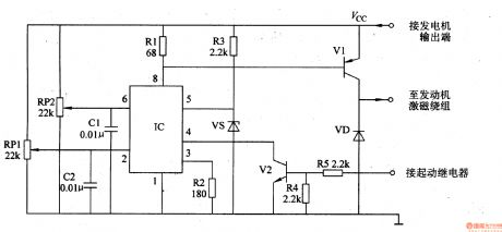
The circuit consists of time-based integrated circuit IC, potentiometer RP1, Rm, capacitor C1, C2, resistor R1-R5, stabilizing diode VS, diode VD and transistor V1 and V2. (It is showed in picture 7-144.)
Turn on the power switch of the mobile and the motor is starting. Here V2 is transmitted. When the motor works, V2 is cut-off. The exporting voltage of the AC motor is adjusted by R3 and VS. Then it supplies 6V reference voltage to pin5 of IC. When the exporting voltage is less than 14.4 V, the exporting voltage on the motor is increasing. When the exporting voltage reaches 14.9V, the exporting voltage is decreasing. The process repeats to keep the exporting voltage in the range of 14.4-14.9V.
RP1 is used to set the least voltage.
RP2 is used to set the highest voltage. (View)
View full Circuit Diagram | Comments | Reading(709)
Voltage Regulator (the 5th)
Published:2011/7/3 5:07:00 Author:Felicity | Keyword: Voltage Regulator (the 5th)
Work of the circuit
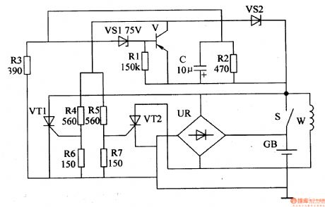
The circuit consists of time-based integrated circuit IC, potentiometer RP1, Rm, capacitor C1, C2, resistor R1-R5, stabilizing diode VS, diode VD and transistor V1 and V2. (It is showed in picture 7-144.)
When the motor van is working, the exporting voltage of W is rectified by UR. It then charges the battery TB and supplies power to the electrical equipment such as the light on the car. When the speed of the motor is low, the charging voltage on GB is lower than 14.5V. The exporting voltage is rectified by UR and then charges GB. When the speed of motor is high, the charging voltage on the GB is increasing. When the voltage is larger than 14.8V, the exporting current is shunted. In this way the charging voltage is stabilized to the value of 14.8V. (View)
View full Circuit Diagram | Comments | Reading(670)
Ultra-low-frequency Infrared Therapeutic Instrument
Published:2011/7/10 23:04:00 Author:Felicity | Keyword: Ultra-low-frequency Infrared, Therapeutic Instrument,
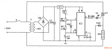
Work of the circuit
The circuit consists of power circuits, ultra-low frequency oscillator and control circuit. (It is showed in picture 9-29.)
Power circuits consists of power switch S, the power transformer T, bridge rectifier, UR, filter capacitors Cl and three-terminal voltage regulator integrated circuit IC1.
Ultra-low frequency oscillator consists of resistors Rl, R2, potentiometer RP, diodes VDl, capacitors C2, C3 in a timely manner based integrated circuit IC2.
Control circuit consists of Resistor R3, LED VL, thyristor VT and diode VD2. (View)
View full Circuit Diagram | Comments | Reading(1025)
The long distance remote control switch which is composed of the S%26P27A/S%26P278
Published:2011/6/14 3:00:00 Author:TaoXi | Keyword: remote control, long distance
(a) is the remote control transmitter circuit, this circuit uses the digital coding circuit VD5026 as the address encoder, and it uses the three-state encoding mode and can compose multiple extensions (the transmitter is used as the extension or the receiver is used as the extension). (b) is the receiving circuit, it is composed of the receiver module and the decoding circuit VD5027 and the relay K.
(View)
View full Circuit Diagram | Comments | Reading(1009)
Health Therapeutic Instrument
Published:2011/7/10 22:55:00 Author:Felicity | Keyword: Health, Therapeutic Instrument,
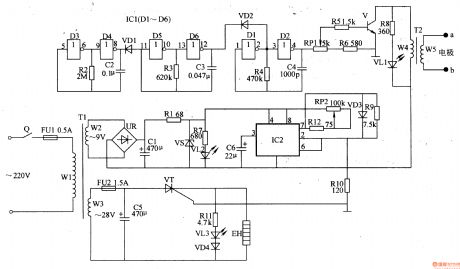
Work of the circuit
The circuit consists of power supply circuit, electrical pulse generator circuit and magnetic thermal control circuit. (It is showed in picture 9-30.)
Power supply circuit consists of timer Q, fuse FUl, FU2, power transformer Tl, bridge rectifier, UR, filter capacitor Cl, C5, voltage regulator diode VS, current limiting resistor Rl, R7, and power indicator LED VLl.
Electrical pulse generator circuit consists of six non-gate integrated circuit ICl (Dl-D6), resistors R2-R6, R8, potentiometer RPl, capacitors C2-C4, diode VDl, VD2, transistors V and pulse transformer T2.
Magnetic thermal control circuit consists of time-base integrated circuit lC2, resistors R9-Rl2, potentiometer RP2, capacitor C6, diode VD3, VD4, light-emitting diodes VL3, thyristor VT and electric heater EH.
(View)
View full Circuit Diagram | Comments | Reading(1121)
The Pulse dialing nine-channel infrared remote control circuits of the LR40992 and μPC1373
Published:2011/7/8 6:00:00 Author:TaoXi | Keyword: Pulse dialing, nine-channel, infrared remote control
The transmitter circuit:
The receiver circuit:
(View)
View full Circuit Diagram | Comments | Reading(877)
Pulse dialing ten-channel infrared remote control circuits of the UM9151 and μPC1373
Published:2011/7/8 6:00:00 Author:TaoXi | Keyword: Pulse dialing, ten-channel, infrared remote control
The transmitter circuit:
The receiver decoding and control circuit:
(View)
View full Circuit Diagram | Comments | Reading(883)
Speedy Automobile Finder
Published:2011/7/9 7:40:00 Author:Felicity | Keyword: Speedy Automobile Finder
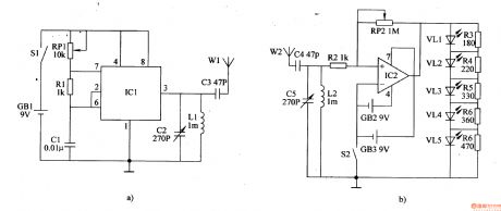
The circuit of this speedy automobile finder consists of transmitter and receiver, as showed in the figure below. The oscillating signal produced by oscillator circuit which consists of IC1, RP1, R1 and C1 transmitted by antenna W1 after being tuned by C2,L1 and C3. The wireless signal which received by W2 is frequency selected by C4, L2, C5 and amplified by IC2 to drive VL1-5. The shorter the distance between the transmitter and the receiver the stronger the signal, and the more the lighted ones of VL1-VL5. Adjusting the resistance of RP1 and RP2 can change the sensitivity of the receiver.
(View)
View full Circuit Diagram | Comments | Reading(630)
| Pages:1570/2234 At 2015611562156315641565156615671568156915701571157215731574157515761577157815791580Under 20 |
Circuit Categories
power supply circuit
Amplifier Circuit
Basic Circuit
LED and Light Circuit
Sensor Circuit
Signal Processing
Electrical Equipment Circuit
Control Circuit
Remote Control Circuit
A/D-D/A Converter Circuit
Audio Circuit
Measuring and Test Circuit
Communication Circuit
Computer-Related Circuit
555 Circuit
Automotive Circuit
Repairing Circuit