
Circuit Diagram
Index 1574
Twinkling Ornamental Illuminations (2)
Published:2011/7/9 1:48:00 Author:Sue | Keyword: Twinkling, Ornamental, Illuminations
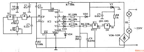
When IC2's Y1-Y3 terminals output high level(when one terminal outputs high level, other terminals will output low level), C4 will be charged. Its voltage will be put on VT's gate electrode through R6,NOT GATE D3,D4 and R8 which will make VT connected. HL will be illuminated. After VT is connected, C4 will charge VT through VD5. Because the resistance values of the resistor R3,R4,R5 are different from each other, when IC2's Y1-Y3 terminals output high level respectively, C4's charge time is different, which will make VT's conductingextents different. Then HL's working voltages are different which will make the illuminations brightness different. The smaller the resistor(R3-R5)'s resistance values are, the longer C4's charge time will be, the larger VT's conducting angle will be, the higher HL's working voltage will be, and the lighter the illuminations will be.
(View)
View full Circuit Diagram | Comments | Reading(590)
Twinkling Ornamental Illuminations (1)
Published:2011/7/10 7:59:00 Author:Sue | Keyword: Twinkling, Ornamental, Illuminations

The 220v ac voltage will provide IC with 12v direct current working voltage after it is rectificated by VD1, limited by R3, stablized by VS, filtrated by C2.
After the multivibrator begins to work, D1's,D2's output terminals will output high level and low level alternately, which will make VT1,VT2 connected and disconnected alternately. Then HL1,HL2 are illuminated alternately(When VT1 is connected, the first circuit of illuminations HL1 are illuminated; When VT2 is connected, the second circuit of illuminations HL2 are illuminated).
By adjusting RP1's and RP2's resistance values and C1's capacity, the multivibrator's oscillate period and frequency can be adjusted. Then the twinkle frequency of HL1,HL2 can be changed. (View)
View full Circuit Diagram | Comments | Reading(525)
200 V / 100 V voltage conversion circuit
Published:2011/7/6 9:07:00 Author:Lucas | Keyword: 200 V , 100 V, voltage conversion
Power transformer will wind primary winding into two groups of coils, and two groups of coils are used in parallel at 100V operation; groups of coils are used in series at 200V operation. When the converter uses half-bridge circuit, it needs the positive and negative power with the core of 0V. It is the best conversion method to directly drive the circuit by the power supply. It is the doubler rectifier circuit when the voltage is 100V, and it is the full-wave bridge rectifier circuit when the voltage is 200V. The flowing current of 100V is double of the 200v , and it uses double-pole-double-throw switch to switch the voltage, and it should be added 100v contacts. (View)
View full Circuit Diagram | Comments | Reading(484)
Automatic Sprinkling Irrigation Controller (4)
Published:2011/7/10 7:24:00 Author:Sue | Keyword: Automatic, Sprinkling Irrigation, Controller
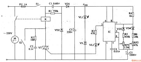
When the switch S1 is on, the 220v ac voltage will generate VDD(12.5-13V) voltage after it is reduced by C1, rectificated by VD1,VD2, filtrated by C3, stablized by VS. The voltage will provide IC with working voltage. After the power circuit begins to work, the LED VL1 is illuminated.
After the power circuit begins to work, besides providing IC with working voltage, VDD voltage also charge the capacitor C5 through resistor R4, diode VD4, resistor R6, potentiometer RP2, capacitor C5. At first IC's pin 6 has low level, IC's pin 3 outputs high level which will make VL2 illuminated and VT connected. The relay K is connected. The electric motor M begins to work and begin to spray. (View)
View full Circuit Diagram | Comments | Reading(480)
Current / voltage conversion circuit composed of LH0032
Published:2011/7/6 9:15:00 Author:Lucas | Keyword: Current conversion, voltage conversion
This is the Current / voltage conversion circuit with fast output voltage rising time, perfect frequency characteristics as the inverting amplifier, high-speed FET input operational amplifier. For making the output be consistent with the polarity of the input signal, Al output end is connected inverting amplifier A2. If you ignore the effects of stray capacitance, the output voltage rising time is about 3OμS, and it will switch the 50nA input current into lV output voltage. In the circuit, R2 is used to prevent the input oscillation; VTl and VT2 are connected as diodes, which is used for input protection of Al. (View)
View full Circuit Diagram | Comments | Reading(449)
LED Festival Illumination Controller (4)
Published:2011/7/8 7:05:00 Author:Sue | Keyword: LED, Illumination, Controller
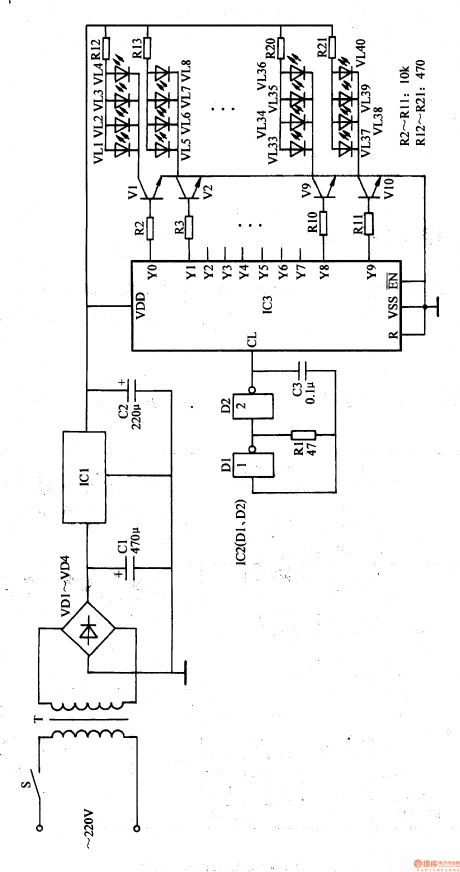
After the autoexciting oscillator begins to work, it will provide IC3 with count pulse. Under the effect of the count pulse, its Y0-Y9 terminals will output high level in turn which will make V1-V10 connected in turn. These LEDs will be drived to be illuminated in turn.
After IC3 is reset, its Y0 terminal will output high level which will make V1 connected. VL1-VM will be illuminated. When its Y1 terminal outputs high level, V2 is connected. VL5-VL8 are illuminated(Y0 terminal return to low level; V1 is disconnected and VL1-VM are off)......When Y8 terminal outputs high level, V9 is connected. VL33-VL36 are illuminated. When Y9 terminal outputs high level, V10 is connected. VL32-VL40 are illuminated. Then different illumination effects can be generated. (View)
View full Circuit Diagram | Comments | Reading(530)
Current / voltage conversion circuit composed of μA741
Published:2011/7/6 8:31:00 Author:Lucas | Keyword: Current conversion , voltage conversion
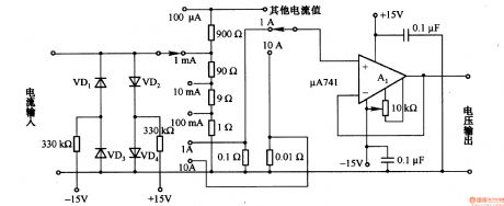
When it makes the current conversion with more than 100mA, you should pay attention on the wiring resistor. If the reference resistance is switched into lΩ or O.lΩ, the wiring cable resistance, base resistance of lead wire can not be ignored. For example, the base resistance is 0.lΩ, in order to control the conversion error in 0.1%, the total wiring resistance is 100μΩ. Also, you should pay attention to resistor heating problem. When the current is lA or more, the resistor will heat, then the temperature of resistor is increased. Due to the effect of temperature coefficient, the reference resistance change will cause conversion errors.
(View)
View full Circuit Diagram | Comments | Reading(769)
LED Festival Illumination Controller (3)
Published:2011/7/10 8:10:00 Author:Sue | Keyword: LED, Illumination, Controller
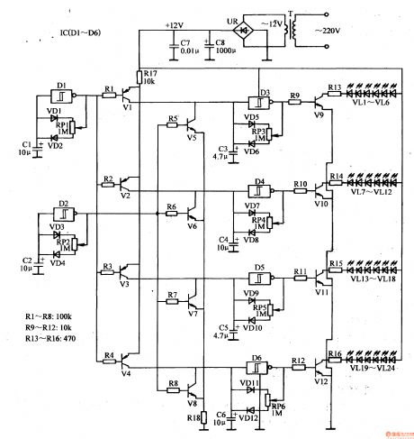
The 220v ac voltage will provide the square wave oscillator, control circuit, drive output circuit with +12v direct current voltage after it is reduced by T, rectificated by UR, filtrated by C7,C8.
The square wave pulse output by D1 will control D3-D6 by V1-V4. The square wave signals output by D2 will control D3-D6 by V5-V8.
When D1 outputs low level, V1-V4 are connected. D3-D6 will stop oscillating because its input terminals are forced to have high level. D3-D6 output low level. Vg-V12 are disconnected at the same time. VL1-VL14 are off at the same time. Then D1 outputs high level which will make V1-V4 disconnected. Square wave oscillator composed of D3-D6 will begin to work. V9-V12 are connected intermittently under the control of square wave pulse. VL1-VL24 are illuminated. (View)
View full Circuit Diagram | Comments | Reading(644)
Current / voltage conversion circuit composed of LM301
Published:2011/7/6 8:09:00 Author:Lucas | Keyword: Current conversion , voltage conversion
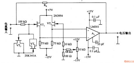
This is a low-input impedance conversion circuit with reference resistor RS being connected to the amplifier's feedback loop and input impedance in approximately zero, and the input current flows into Al's output end through Rs. The maximum switching current is decided by the op amp output current, and the maximum switching current of circuit is lOmA. When it needs to increase the current conversion, the output end of Al can be added current amplifier. VTl and VT2 use 2N3954 FET with the gate leakage current in 5OpA. If gate - drain voltage is reduced, the leakage current can be reduced to lOpA in the normal temperature. VT3 and VT4 are the protection FET (2SKl4lA).
(View)
View full Circuit Diagram | Comments | Reading(3485)
LED Festival Illumination Controller (2)
Published:2011/7/10 8:08:00 Author:Sue | Keyword: LED, Illumination, Controller
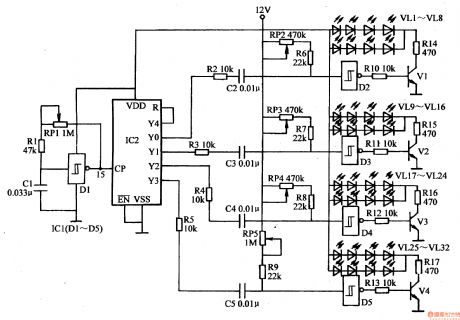
The LED drive circuit consists of IC1's inner trigger D2-D5, resistor R6-R7, transistor V1-V4, potentiometer RP2-RP5 and LED VL1-VL32.
When the power is on, the clock pulse generator circuit begins to oscillate. The trigger D1's output terminal will output clock pulse signals with a frequency of 6Hz. The signals will be put on IC2's CP terminal(pin 15) which will serve as the counter's count pulse. After IC2 counts and allocates the clock pulse signals, its Y0-Y4 terminals will output high level in turn which will promote the circuit to work. (View)
View full Circuit Diagram | Comments | Reading(1292)
Current / voltage basic conversion circuit composed of operational amplifier
Published:2011/7/6 7:45:00 Author:Lucas | Keyword: Current conversion , voltage conversion , basic, operational amplifier
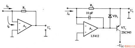
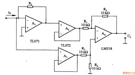
Figure 1-36 (a) shows the current / voltage conversion circuit composed of a single operational amplifier. As the op amp input bias current is not zero, it will produce conversion error. For example, the op amp μA741's bias current IB ≈ 80nA, even if the allowable error is 1%, the minimum switching current is about tens of μA; for Bi-FET input op-amp, IB is about tens of pA, and the minimum switching current is available to a few nA. For the J-FET input op amp, the bias current has a positive temperature coefficient, when the junction temperature increases by 10 ℃, the bias current is increased to 2 times.
(View)
View full Circuit Diagram | Comments | Reading(736)
LED Festival Illumination Controller (1)
Published:2011/7/10 8:05:00 Author:Sue | Keyword: LED, Illumination, Controller
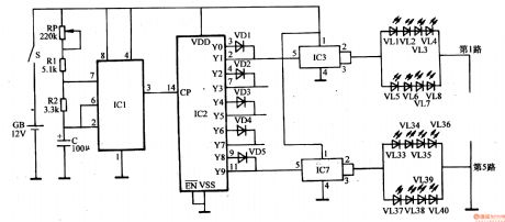
The autoexciting oscillator circuit consists of base integrated circuit IC1, resistor R1,R2, capacitor C and potentiometer RP.
The count freqency divider consists of count/pulse distributor integrated circuit IC2 and diode VD1-VD5.
The electronic switch circuit consists of electronic switch integrated circuit IC3-IC7.
When the power switch S is connected, the autoexciting oscillator begins to work. IC1's pin 3 will output low frequency square wave pulse which will be put on IC2's CP trigger count terminal(pin 14). Then IC begins to count, and its Y0-Y9 terminals will output high level in turn which will make the electronic switch integrated circuit IC3 and IC7 connected in turn. Its output terminals(pin 2 and pin 3)' outside LED will be illuminated. (View)
View full Circuit Diagram | Comments | Reading(630)
Sound Control Twinkling Illuminations (2)
Published:2011/7/8 7:47:00 Author:Sue | Keyword: Sound Control, Twinkling, Illuminations
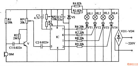
The 220v ac voltage will provide the sound control circuit and IC with +12v working voltage after it is rectificated by VD1-VM, limited and reduced by R4,R5, stablized by VS, filtrated by C4.
After IC begins to work, its pin 1, pin 2, pin 6, pin 7 will output 4 circuits of control signals which will make VT1-VW connected in turn. Then illuminations HL1-HL4 will be drived to be illuminated and generate a running flowing illumination effect. BM will turn the musical signals it receives into electric signals, which will be put on IC's pin5 through C2 after it is amplified by V, volume adjusted by RP1. The signals can adjust the oscillate frequency of IC's inner voltage control oscillator which will make the illumination effects change with the musical signal's rhythm synchronically. (View)
View full Circuit Diagram | Comments | Reading(548)
Sound Control Twinkling Illuminations (1)
Published:2011/7/8 7:35:00 Author:Sue | Keyword: Sound Control, Twinkling, Illuminations
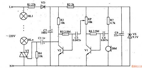
The 220v ac voltage will provide V1 and V2 with +9v working voltage after it is reduced by R1, rectificated by VD, filtrated by π formfilter(consists of C2,R2 and C6), stablized by VS.
BM will transform the audio signals it receives into electric signals, then through C4, the signals will be put to the amplifier which is composed of V1,V2 and the signals will be amplified.The amplified audio signals will be put on VT's gate electrode(G elecrode) through C1 which will control the connection and disconnection states of VT as well as theconduction angle. When there is no sound, VT is disconnected and illuminations HL1-HLn are not illuminated. The louder the sound is, the larger VT'sconduction angle is and the lighter the illuminations are. (View)
View full Circuit Diagram | Comments | Reading(481)
Automatic Sprinkling Irrigation Controller (3)
Published:2011/7/10 7:10:00 Author:Sue | Keyword: Automatic, Sprinkling Irrigation, Controller
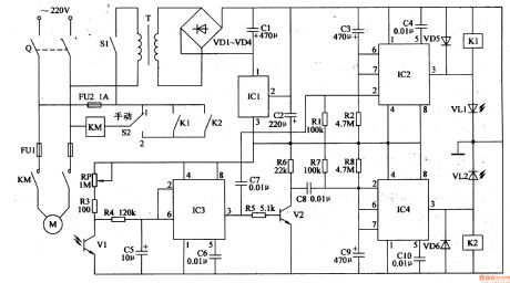
After the knife switch Q is on, if S2 is put on 1 (manual), the ac contactor KM will be connected. Its normally open contact will be connected and the electric motor will begin to work. If S2 is put on 2 (automatic), then only when the relay K1 or its normally open contact is connected that KM can be connected and M can begin to work.
In the automatic condition(when S2 is put on 2 ), when the power switch S1 is on, the 220v ac voltage will provide IC1-IC3 with +12v working voltage after it is reduced by T, rectificated by VD1-VD4, filtrated by C1, stablized by IC1. (View)
View full Circuit Diagram | Comments | Reading(645)
Voltage / frequency conversion circuit composed of TA7505
Published:2011/7/7 6:13:00 Author:Lucas | Keyword: Voltage conversion , frequency conversion
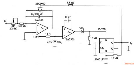
The circuit is composed of the ramp generator, Miller integration circuit, voltage comparator, etc., and it can switch 0-10V input voltage into the corresponding 0-100HZ output frequency. Circuit's switching frequency is determined by the Al ramp generator, and the conversion error is mainly caused by the integrator reset time, dielectric absorption of integration capacitor. In order to reduce errors caused by the reset time, the output of the comparator is connected the trigger composed of TC4013.
(View)
View full Circuit Diagram | Comments | Reading(886)
Automobile Fuel Supply Indicator
Published:2011/7/10 7:32:00 Author:Sue | Keyword: Automobile, Fuel Supply, Indicator
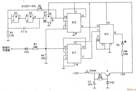
The automobile's storage battery's +12v voltage will output +5v voltage from V's emitting electrode after it is filtrated by L,C2, adjusted by V, stablized by VS2. The voltage will provide the pulse oscillator, counter, LED indicator circuit with working voltage.
The detecting pulse which is output by the oil pressure sensor will be put on IC2's pin 3 and IC3's pin 14 through the level converter. When the input detecting pulse signal has low level, R4's voltage is lower than 0.4 v. When the input pulse signal has high level, R4's voltage reaches 2.7V.
After the pulse oscillator begins to work, it will provide IC2 with count pulse signal with a frequency of 500Hz. (View)
View full Circuit Diagram | Comments | Reading(621)
Voltage / pulse train conversion circuit composed of TC4013
Published:2011/7/7 6:33:00 Author:Lucas | Keyword: Voltage conversion , pulse train conversion
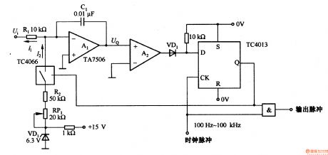
In the circuit, Al is charge-balanced integral amplifier. When UQ <O, the analog switch TC4066 is synchronously disconnected under the rising effect of the of clock, and Al integrates the input voltage Ui, and integral time constant is decided by Rl and Cl, Al output UQ is increased exponentially; When UQ> O, TC4066 is synchronously connected under the effect of clock, and integral circuit makes the reverse integration, and UQ is decreased exponentially; when UQ = O, the integral amplifier is used in combination with the comparator, which is synchronously controlled under the effect of clock to output pulse train which is proportional to input.
(View)
View full Circuit Diagram | Comments | Reading(2069)
Motorcycle Deceleration Indicator
Published:2011/7/10 5:34:00 Author:Sue | Keyword: Motorcycle, Deceleration, Indicator

When the motorcycle has a constant speed, the deceleration automatic switch S1 is disconnected and IC's pin Z and pin 4 both have high level. HL is not illuminated. When the motorcycle is slowing down, according to the mechanics principle, the motorcycle will have a negative acceleration, which will make S1's inner moving contact have a forward driving force. Then the moving contact and the fixed contact will be connected and IC's pin Z and pin 4 will have low level and HL is illuminated.
C is the time-delay capacitor. When S1's moving contact and fixed contact are disconnected, C is charged through R2. When C's voltage reaches 1.6v, IC's pin 4 becomes high level. Then the occasion that the brake lamp HL will not twinkle when the motorcycle is running on an uneven road will be avoided. (View)
View full Circuit Diagram | Comments | Reading(694)
Voltage / frequency conversion circuit composed of μA709
Published:2011/7/7 6:40:00 Author:Lucas | Keyword: Voltage conversion, frequency conversion
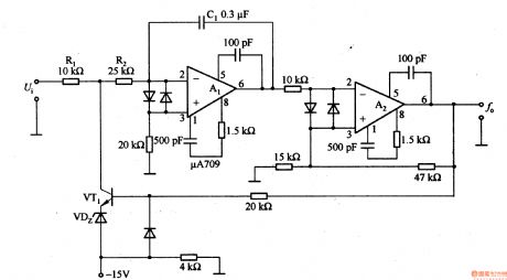
Al integrates the input voltage Ui, and the Schmitt circuit is connected to Al to switch output level and make VT1 saturated conduction. As VTl emitter is clamped by VDZ IN 9V, therefore, VTl collector potential is approximately-9V. Al makes reverse integeration on the voltage, then the output changes from negative to positive, and the time constant is determined by R2 and Cl. If over voltage of Al output is not sensitive, VTl closes again, Al integrates the input voltage again. The circuit swicthes +1 to + lOV input voltage into 0.1 to lkHZ frequency pulse signal.
(View)
View full Circuit Diagram | Comments | Reading(897)
| Pages:1574/2234 At 2015611562156315641565156615671568156915701571157215731574157515761577157815791580Under 20 |
Circuit Categories
power supply circuit
Amplifier Circuit
Basic Circuit
LED and Light Circuit
Sensor Circuit
Signal Processing
Electrical Equipment Circuit
Control Circuit
Remote Control Circuit
A/D-D/A Converter Circuit
Audio Circuit
Measuring and Test Circuit
Communication Circuit
Computer-Related Circuit
555 Circuit
Automotive Circuit
Repairing Circuit