
Circuit Diagram
Index 1565
wireless proportion motor remote controller circuit
Published:2011/7/9 10:09:00 Author:Lena | Keyword: wireless, proportion, motor, remote controller
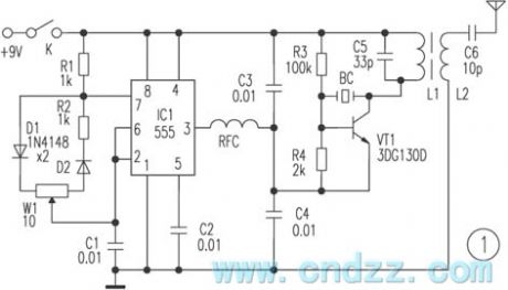
The tri-proportion remote control device is widely used in vehicle model, aeromodelling region etc, which can realize the autocontrol of target drone, model ship and toys. Here introduces a tri-proportion remote controller, the component is purchased easily. The controller has the simple principle and stable performance etc features, which is suited to make unprofessionally.Work principle Figure 1 shows a remote control transmitting circuit, 555 integrated block and R1, R2, W1,D1,D2 and C1 form astable wide range variable dutycycle oscillator, parameter oscillator frequency shown in the figure is about 50Hz.
(View)
View full Circuit Diagram | Comments | Reading(3225)
Dangerous Area Warning Device (the 1st)
Published:2011/7/7 9:49:00 Author:Felicity | Keyword: Dangerous Area Warning Device, the 1st
Work of the circuit
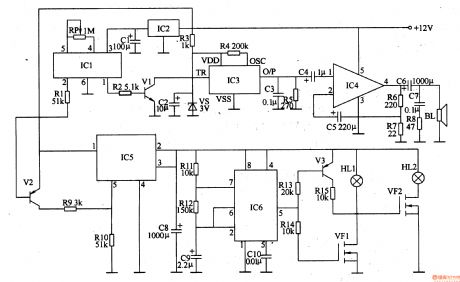
The circuit consists of regulator circuit, pyroelectric infrared detection trigger circuit, electronic switching circuits, voice circuits, audio power amplifier, low-frequency oscillator and flash drive circuit. (It is showed in the picture 8-121.)
Regulator circuit consist of three-terminal voltage regulator integrated circuit IC2, resistor R3, zener diode VS and filter capacitor Cl, C2.
Pyroelectric infrared detection trigger circuit consists of pyroelectric infrared detection module ICl, transistors Vl, V2, resistors Rl, R2 and potentiometer RP.
Electronic switching circuit consists of electronic switch integrated circuit IC5, resistors R9, RlO and capacitor C8.
Audio power amplifier consists of power amplifier integrated circuit IC4, resistors R6-R8, capacitor C4-C7 and speaker BL.
Low-frequency oscillator consists of Time-base integrated circuit IC6, resistors R11, R12, and capacitor C9, C10.
Flash drive circuit consists of transistor V3, resistors R13-Rl5, field-effect transistors VF1, V F2and light HLl, HL2. (View)
View full Circuit Diagram | Comments | Reading(1496)
cordless phone as remote controller circuit
Published:2011/7/9 9:23:00 Author:Lena | Keyword: cordless phone, remote controller
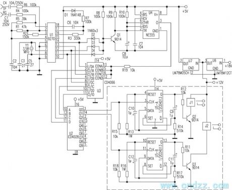
Assembling cordless phone seater and control circuit introduced in the text can obtain the remote control receiver function. Using cordless phone mobile phone as a remote controller transmitter, we can control electric light, electric fan and TV set etc household appliance work.This controller circuit is shown as the figure, TP and RG end connect phone exterior line, namely the circuit is merged with seater. To prevent bringing error when we dial phone, the circuit specially designs the access code using key number as control signal. U1(9270) is DTMF decode integrated circuit.
(View)
View full Circuit Diagram | Comments | Reading(2143)
5V-12V Switch Power Supply Circuit Based on MAX761
Published:2011/6/20 22:40:00 Author:Michel | Keyword: 5V-12V, Switch Power Supply, Circuit
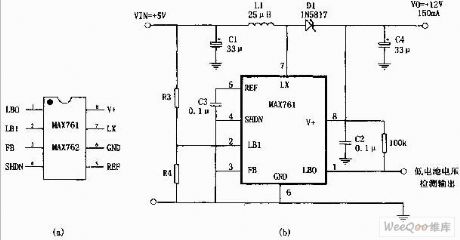
The 5V-12V boost power supply shown in the picture is composed of high efficiency,low power consumption boost DC converter,MAX761 and a few peripheral components.Its features are: First,transformation efficiency is 86%.Second,static currentis 110μA.Third, with low battery voltage detection function.R3 and R4 in the picture are testing dividing resistor and they can be caculated according to experience formula: R4=R3(VTPIP/1.5-1),VTPIP is test trigger voltage. (View)
View full Circuit Diagram | Comments | Reading(852)
temperature detection, voltage-frequency switch circuit
Published:2011/7/9 9:29:00 Author:Lena | Keyword: temperature detection, voltage-frequency switch
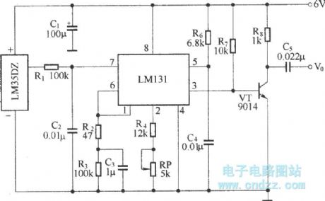
As shown in the figure, the temperature detection, temperature-voltage switch and voltage-frequency switch circuit is used to remote detect temperature. We connect the circuit and wireless transmitting circuit forming a temperature detection remote control transmitting circuit. In the circuit, temperature detection and temperature-voltage switch adopt integrated temperature sensor LM35DZ, this circuit detection temperature range is 0~100℃±O.25℃, linearity span range is 10mV/℃, work voltage range is 4~30V. Voltage-frequency switch circuit adopts special voltage-frequency switch integrated circuit LM131.
(View)
View full Circuit Diagram | Comments | Reading(2867)
satellite receiver remote control AC on/off circuit
Published:2011/7/9 10:08:00 Author:Lena | Keyword: satellite receiver, remote control, AC, on/off
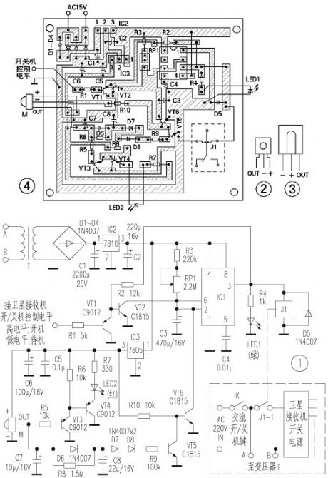
Here introduces a satellite receiver remote control AC on/off circuit, it can be fixed in the receiver, and use former remote controller to realize remote control delay AC on/off function. This circuit has simple structure, easily purchased component, simple manufacture, specially suited for unprofessional electron fans to make.Work principle: The circuit is shown as figure 1. Commercial power is stepped-down by transformer T, and be commuted by rectifier diodes D1-D4, and be regulated by voltage regulator block 7810, 7805, and be filtered by capacitance C1, C2, C5, C6, then it supplies power for the entire circuit.
(View)
View full Circuit Diagram | Comments | Reading(1628)
Industrial Instrument Used Sound And Light Alarm Two
Published:2011/7/9 6:35:00 Author:Felicity | Keyword: Industrial Instrument, Sound And Light Alarm
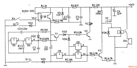
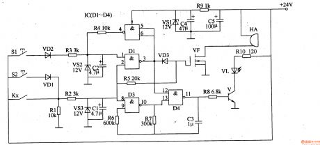
Work of the circuit The circuit consists of + l2V regulator circuit, the switching control circuit, oscillator, bistable trigger circuit and sound and light alarm. (It is showed in picture 8-120.)+ l2V regulator circuit consists of resistors R2, R3, filter capacitor Cl, C5, C6 and regulator diode VS.The switching control circuit consists of resistors Rl, Rl2, mix together goose control VLC and industrial instrumentation control contact (controlled by electrical contacts) Kx.Oscillator consists of NAND gate IC IC (Dl-D5) within the Dl, D2 and the diode VD2, resistors Rll, capacitors C2, C3.Bistable trigger circuit consists of D3-D5 within IC and resistor R7.Sound and light alarm consists of transistor Vl-V3, resistor R4-R6, Rg, RlO, light-emitting diodes VL, diodes VD3, VD4, VD6, field-effect transistors VF, K and alarm relay HA. (View)
View full Circuit Diagram | Comments | Reading(621)
Industrial Instrument Used Sound And Light Alarm One
Published:2011/7/9 6:35:00 Author:Felicity | Keyword: Industrial Instrument, Sound And Light Alarm
Work of the circuit The circuit consists of sound and light alarm circuits, measurement and control circuit, bistable trigger, LED flash circuit, sound the alarm circuit and the + l2V voltage regulator circuit. (It is showed in picture 8-119.)Sound and light alarm circuit consists of industrial instrument control contact (controlled by electrical contacts) K,, resistors Rl, R2, zener diodes VS3and capacitors Cl.Bistable trigger consists of NAND gate IC IC (Dl-D4) within the D3, D4, resistors R6-R8, RlO, capacitor C3, transistor V and light emitting diodes VL.LED flash circuit consists of resistor R5, field-effect transistors VF and alarm HA.Sound the alarm circuit consists of IC internal D1, D2, resistor R3, R4, diode VD2, VD3, voltage regulator diode VS2and capacitor C2. The + 12V voltage regulator circuit Resistor Rg, capacitors C4, C5 and the voltage regulator diode VSl.
(View)
View full Circuit Diagram | Comments | Reading(529)
10-way infrared sequence remote control circuit
Published:2011/7/9 10:02:00 Author:Lena | Keyword: 10-way, infrared, sequence, remote control
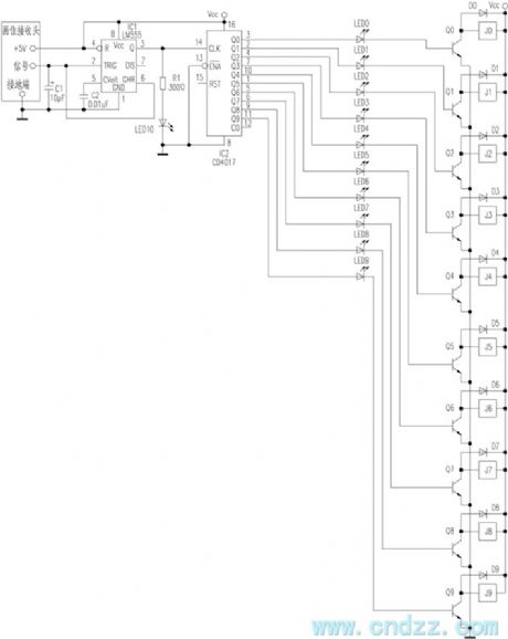
Here introduces a kind of infrared remote control emitter using common household appliance to control 10-way sequence remote control and display circuit. Remote control emitter can adopt usual color TV, video tape recorder , air-condition etc kinds of infrared remote control emitters. So in the manufacture process, we only need product infrared receptor circuit. Infrared receptor circuit mainly consists of integrated infrared receptor apex, NE555 and CD4017 etc integrated circuit, the remote control distance can reach about 15 meters.The circuit is shown in the figure.
(View)
View full Circuit Diagram | Comments | Reading(776)
realizable far distance remote control simple circuit
Published:2011/7/9 9:59:00 Author:Lena | Keyword: realizable, far distance, remote control, simple

The principle and production process of this circuit are as follows:
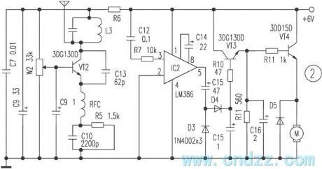
Infrared receptor apex REM can select currency integration infrared receptor apex, the shape is shown in the figure 1, the infrared remote control signal received by REM is amplified by V1, V2, and the signal drives infrared transmitting tube work. Except for broken line part of figure 1, the other is put in the living room, infrared emitter diode connects coaxial line and receiving part, then be put front shadow of bedroom satellite receptor.
When you possess of this device, you can select TV program that you want conveniently in living room.
(View)
View full Circuit Diagram | Comments | Reading(579)
practicality electromotion curtain remote control circuit 1
Published:2011/7/9 9:57:00 Author:Lena | Keyword: practicality, electromotion curtain, remote control
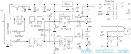
The transmitting/receiving part of this device uses T966/T988 multiway wireless transceiver module. The transmitting part adopts T966 2-key type emitter, and the receiving part work principle is shown in the figure.
Turn on the power supply, IC2 is restored, Q1 and Q2 output low level, T1 and T2 cut-off, J1 and J2 are not absorbed, motor M stops, the curtain jibs. When press remote control transmitting key C, C end of IC0 outputs high level, D1 cuts-off, I0 end outputs high level, then the high level shape is changed through IC1-1, IC1-2 and is sent to CP1 end of IC2-1.
(View)
View full Circuit Diagram | Comments | Reading(933)
Three-phase-bridge Rectifier Circuit of Resistance Load
Published:2011/6/19 7:59:00 Author:Michel | Keyword: Resistance Load, Three-phase-bridge Rectifier Circuit
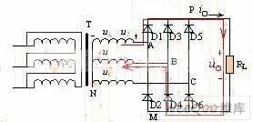
Single-phase rectifier circuit's power usually is less than one kw and high power rectifier circuit need three-phase rectifier circuit, because the high power rectifier circuit is three-phase ac power supply form. The picture is a resistance loading three-phase bridge rectifier circuit.It has six pieces of diodes,D1,D3 and D5 form cathode and are standed by P.D2,D4 and D6 form anode and M stands for them.And N stands for zero line. (View)
View full Circuit Diagram | Comments | Reading(1458)
sound surface wave resonator application circuit in the wireless remote control
Published:2011/7/9 9:43:00 Author:Lena | Keyword: sound surface wave, resonator, application circuit, wireless remote control
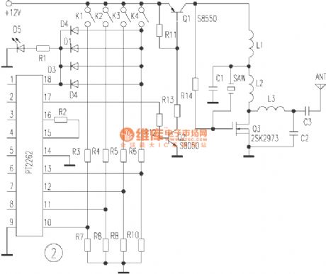
R11-R13, Q1 and Q2 form electron switch modulation circuit, when encoder outputs high level, Q1 conducts, and oscillator emitter electrode works. When encoder outputs low level, Q1 stops to complete ASK modulation. R14, Q3, C1, L1, L2 and sound surface resonator SAW constitutes 315MHZ power master oscillator, Q3 is a high frequency field effect transistor, which can output 1.5W power at 450MHz.
(View)
View full Circuit Diagram | Comments | Reading(1033)
Digitally-controlled 555 Astable Multi-vibrator
Published:2011/7/4 22:05:00 Author:Zoey | Keyword: Digitally-controlled, 555 Astable Multi-vibrator
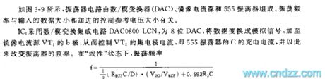
As shown in the figure 3-9, the vibrator circuit consists of anA/D converter, mirror current source, and a 555 oscillator. The scillation frequency is related to the data input and the controllable reference voltage added.
IC1 uses anA/D converter to transform the integrated circuit DAC0800LCN, an eight-digit DAC, and to transform the data to ananlog signal and add it to the b-pole of the mirror current source,so as to control thecollector current,orthe charge current of C in 555 oscillator, to change the frequency of the oscillator.when inlinearity condition, oscillator frequency
f=1/1/3(RpefC/D). (VDD/Vref)+0.693R3C (View)
View full Circuit Diagram | Comments | Reading(1041)
Three LED Circuit Driven by MAX1574 Charge-Pump
Published:2011/6/19 7:24:00 Author:Michel | Keyword: Charge-Pump, Three LED Circuit
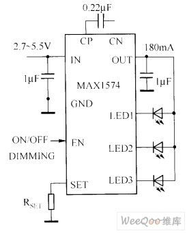
The white LED circuit driven by MAX1574 charge-pump is showed as above.This circuit uses 180mA current to drive three whiteLED.
1 MHz switching frequencies allows the charge pump touse small size ceramic capacitors.
Picture:Three LED Circuit Driven by MAX1574 Charge-Pump (View)
View full Circuit Diagram | Comments | Reading(671)
Thyristor AC Automatic Voltage Control and Regulation Circuit
Published:2011/6/20 21:33:00 Author:Michel | Keyword: Thyristor, AC, Voltage Control and Regulation, Circuit
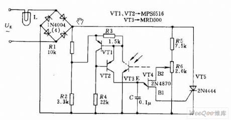
The circuit shown as above uses thyristor AC automatic voltage regulating circuit to stabilize the brightness of projector lamps,L.For this,it accesses thyristor T5 via a diagonal line of communication bridge.And its triggering pulse is generated by single thyristor VT4.Thyristor VT1,VT2 and light activated triode VT3 have the equivalent resistance function.When projection's light changes as the power supply alters,resistance value of light activated triode changes,the voltage phase of the control junction transistor alters.The aboved changes trigger thyristor' pusle phase shift and increasing or reducing thyristor conduction time makes voltage and brightness of the light projection approximately remains unchaged,which stablizes the lightness. (View)
View full Circuit Diagram | Comments | Reading(2009)
555 Bootstrap Sawtooth wave Generator Circuit
Published:2011/7/4 21:59:00 Author:Zoey | Keyword: 555 Bootstrap , Sawtooth wave, Generator Circuit
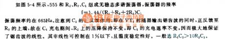
As shown in the figure 5-4, the 555, R2, R3 and C1 constitute a Bi-stable multi-vibrator,the frequency of the Bi-stable multi-vibrator f=1.44/ (R1+R2+2R3)C1 and the oscillation frequency is about 665Hz. Much attention should paid on the positive feedback effect of C2, that is, at the same time that emitter follower VT1 outputs sawtooth wave, the positive feedback goes to the upside of R2.Therefore, the pressure drop on R2 remains unchanged, that means the charge rate of C1 remains unchanged, too. Thus, the linearity of the sawtooth wave is greatly guaranteed. Nonlinearity can be limited to below 1% with excellent temperature stability, generally, it is chose under the condition R1C2>10R2C1. (View)
View full Circuit Diagram | Comments | Reading(1103)
Basic White LED Drive Circuit of Switch Converter
Published:2011/6/28 5:32:00 Author:Michel | Keyword: Switch Converter, White LED, Drive Circuit
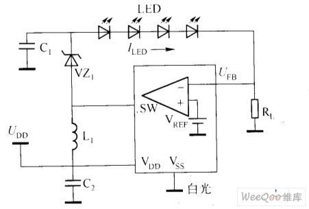
Basic White LED Drive Circuit of Switch Converter (View)
View full Circuit Diagram | Comments | Reading(670)
MA1576Y Charge - pump Driven Two Groups of LED Circuit
Published:2011/6/19 6:37:00 Author:Michel | Keyword: Charge - pump, Driven , Two Groups, LED Circuit
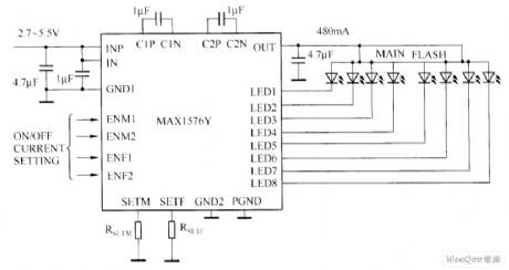
The MA1576Y charge - pump driven drive white LED Circuit is showed as above.This circuit can use 480mA general current to drivr two groups of white LED(every group has 4 white LED).For the flashing white LED group, this circuit allows each white LED current to reach 100 mA.Each group of white LED has independent the current set, pulse brightness modulation and two lines brightness control.Using the adaptive switch, in the whole process of discharging of a single lithium ion battery, circuit average efficiency can reach 83% .For the digital camera which uses white LED,it's an ideal choice to choose white LED drive circuit composed of MAX1576Y.
MA1576Y Charge - pump Driven Two Groups of LED Circuit
Picture: (View)
View full Circuit Diagram | Comments | Reading(633)
555 Symmetrical wave Multi-vibrator
Published:2011/7/4 22:58:00 Author:Zoey | Keyword: 555 Multi-vibrator, Symmetrical wave
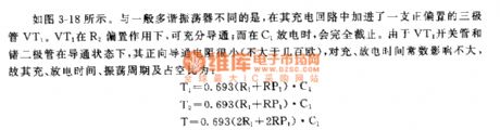
As shown in the figure 3-18, this multi-vibrator has added a positive bias triode VT1. With the positive bias effect of R2, VT1 can be fully conducted; but as soon as C1 discharges, it will not be conducted. As the switch pipe VT1 and Germanium diode is in the state of conduction, the positive conduction resistance is weak, so it has little effect on charge and discharge time constant. The charge time, discharge time, oscillation period and duty cycle can be calculated by following formula:
T1=0.693(R1+RP1)•C1
T2=0.693(R1+RP1)•C1
T=0.693(2R1+2RP1)•C1
D=T2/D=50%
Another merit of this circuit is, the load change has little effect on voltage output, duty cycle and oscillation frequency.
Figure 3-18 Multi-vibrator that can output symmetrical wave
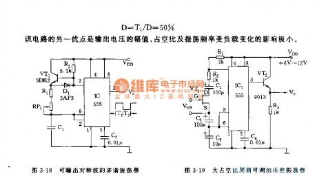
Figure 3-19 Voltage-controlled oscillator with an adjustable duty cycle period
(View)
View full Circuit Diagram | Comments | Reading(2157)
| Pages:1565/2234 At 2015611562156315641565156615671568156915701571157215731574157515761577157815791580Under 20 |
Circuit Categories
power supply circuit
Amplifier Circuit
Basic Circuit
LED and Light Circuit
Sensor Circuit
Signal Processing
Electrical Equipment Circuit
Control Circuit
Remote Control Circuit
A/D-D/A Converter Circuit
Audio Circuit
Measuring and Test Circuit
Communication Circuit
Computer-Related Circuit
555 Circuit
Automotive Circuit
Repairing Circuit