
Circuit Diagram
Index 1567
Typical Applied Circuit of ZXSC310
Published:2011/6/19 5:32:00 Author:Michel | Keyword: Typical Applied Circuit
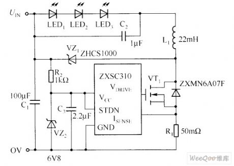
The showing circuit provides a drive power white LED solutions, that is,white LED is driven by working in the buck model of standard boost converter.This solution efficiency is as high as 96%, compared with standard solution efficiency with only 85%, it has a lot of practical advantages.
When MOSFET (VT1) turns on ,the current flows through white LED and it connects with filter capacitor(C2),inductance (L1) and test resistor(R1) in series-parallel way.The current value is decided by test resistor value and test voltage threshold of ZXSC310(It's usually 19mV). (View)
View full Circuit Diagram | Comments | Reading(1318)
Fixed Bias Voltage and Current-limiting Resistor Drive LED Circuit
Published:2011/6/19 6:51:00 Author:Michel | Keyword: Fixed Bias Voltage, Current-limiting Resistor, Drive, LED Circuit
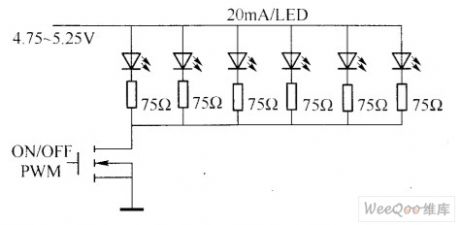
In the application of white LED the most obvious problems is the matching differences of the product.According to white LED typical specifiactions,when the current is 20mA,the minimum value of the forward voltage is 3.5V and the maximum value is 4.0V.Obviously, constant voltage source is not reasonable solution.The same current drives every LED, which can get brightness but the cost is high.Most applications are simply using fixed bias voltage and current limit resistance to obtain approximate matching white LED brightness and it is showed as above.
Picture:Fixed Bias Voltage and Current-limiting Resistor Drive LED Circuit (View)
View full Circuit Diagram | Comments | Reading(892)
infrared remote control circuit(TR1300/1315,PIC12043)
Published:2011/7/8 22:38:00 Author:Lena | Keyword: infrared, remote control
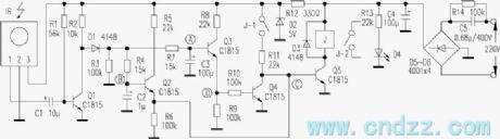
The same as digital coding circuit, encode outputted by code hopping encoding circuit can be transmitted by infrared ray or radio wave. At the receiving end, modulation signal received by receiving circuit, demodulation circuit is amplified and demodulated, then the code hopping decode chip outputs analyzed channel data, to control relevant circuit by executing circuit. Infrared remote control circuit shown in the figure consists of code hopping chip TR1300/1315 and infrared remote control receiving module PIC12043.
remote control receiving circuit:
infrared receiving demodlation decode and output circuit:
(View)
View full Circuit Diagram | Comments | Reading(518)
infrared remote control mouse work principle
Published:2011/7/8 22:42:00 Author:Lena | Keyword: infrared, remote control, mouse, work principle

infrared remote control mouse work principle
A infrared remote control mouse consists of infrared emitter and infrared receiver two parts, the principle block diagram is shown as figure 3.A infrared emitter circuit is shown in figure 4.IC1 is a encoder integrated circuit VD5026, the matched encoder integrated circuit is VD5027 or VD5028. 1-8 pins of VD5026 are address end A0-A7, 10-13 pins are data end D0-D3(when coordinated with VD5028, they can be used as address A8-A11 ),17 pin is encode signal output end, the outputted signal by 17 pin can modulate signal which is generated by 40kHz pulse generator, the pulse generator consists of IC2A,IC2B etc.
(View)
View full Circuit Diagram | Comments | Reading(1267)
simple banausic remote control switch circuit
Published:2011/7/9 8:50:00 Author:Lena | Keyword: simple, banausic, remote control, switch
This remote control switch only uses 5 triodes, the entire circuit can be installed on the 40mm×50mm circuit board to control different electric devices on/off remotely, the circuit is shown in the figure. The remote control emitter is common household appliance remote controller. As long as the receiving control circuit is welded according to the figure, it will be success without debugging.IR is a infrared remote control receiving end, when there is no infrared signal, ① pin outputs high level, when there is a infrared signal, ① pin outputs a series of low level pulse.
(View)
View full Circuit Diagram | Comments | Reading(612)
facility currency infrared remote control receiving circuit
Published:2011/7/8 22:52:00 Author:Lena | Keyword: facility, currency, infrared, remote control, receiving
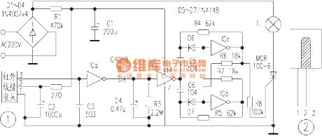
At present, the quantity of TV, VCD, VCR etc infrared remote control emitters is increasing. This design of the circuit aims at their performance, making the remote control emitter to exert another purpose: emit infrared signal, control lighting lamp and the control distance is >8 meters.Circuit principle: This infrared control switch circuit is shown in figure 1, which mainly consists of infrared receiving end and IC4069. When the infrared receiving end is static, the circuit outputs high level. When the circuit receives infrared pulse signal that is sent by remote control emitter, tail edge outputs low level (pulse signal).
(View)
View full Circuit Diagram | Comments | Reading(600)
family satellite and cable television in the common cable and remote control circuit
Published:2011/7/8 22:57:00 Author:Lena | Keyword: family, satellite, cable television, common cable, remote control
Family usually only use satellite receiver aside the TV set to watch satellite television, but it’s difficult in another room. Now, I use former cable television line, mixing the satellite television signal and cable television signal to transfer in the common cable, to realize all the TV sets can watch satellite television in one family. Common cable connecting circuit is shown as figure 1. Satellite receiver RF output end outputs U segment satellite television signal that is amplified by triode VT1, then mix the amplified signal and cable TV signal through 75-3 feedback line.
(View)
View full Circuit Diagram | Comments | Reading(497)
laser transmitter linearity controlling circuit diagram
Published:2011/6/18 21:22:00 Author:Lena | Keyword: laser transmitter, linearity controlling
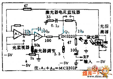
Using optics feedback technology can keep invariable laser output inawide temperature change range.This circuit is a optics negative feedback that is not sensentive to temperture range.
(View)
View full Circuit Diagram | Comments | Reading(581)
oscillating circuit and trigger circuit diagram
Published:2011/6/18 21:19:00 Author:Lena | Keyword: oscillating circuit, trigger circuit
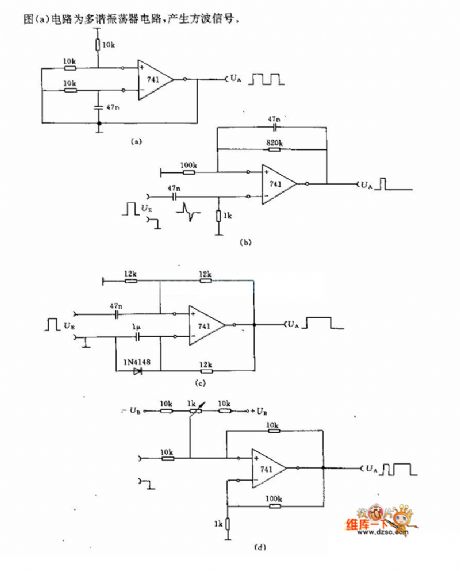
Diagram (a) circuit is a multivibrator type oscillating circuit which can generate Square-Wave signal.
(View)
View full Circuit Diagram | Comments | Reading(564)
infrared modulation demodulation circuit diagram
Published:2011/6/18 21:33:00 Author:Lena | Keyword: infrared, modulation, demodulation
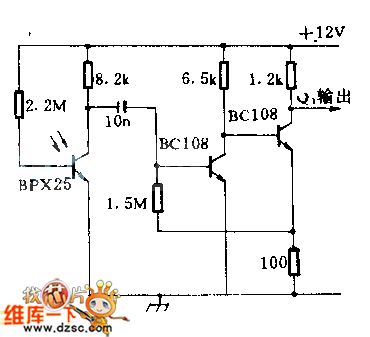
When a 1lx peak value light signal isinputted in the photoelectric cell,then the signalgo through bipolar amplifier,will output 400mV peak value;the detector sensitivity at 4KHZ is lower 3dB than at 1KHZ;when using F:2 calibration ten or parabola reflector on the infrared signal source and detector,the detect distant can be 30.48m(100 feet).This circuit can be used in high secrecy communication system.
(View)
View full Circuit Diagram | Comments | Reading(1245)
MN|4821JTD(TV) remote control microprocessor
Published:2011/7/8 9:25:00 Author:Lena | Keyword: TV set, remote control, microprocessor
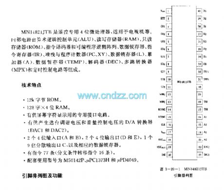
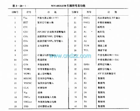
MN14821JTB is a remote control 4-bit microprocessor, usually used in TV set etc. The internal circuit consists of Arithmetic Logical Unit (ALU),Random-access memory(RAM),Read-only memory(ROM),instruction encoder and Programmable Logic Array, data flip-latch, instruction register, stack and program counter(PC,XY),data flip-latch(L),accumulator(A),data register(TEMP),decoder(DEC),multiplexer(MPX) and timing control circuit.
Specifications:
12k byte ROM
128 *4 bit RAM
Special interface circuit is used to display characters in the screen
D/A converter (DAC1 and DAC2) used for produce selective tuned voltage and volume control voltage
two 4-bit input ports(A and B),two 4-bit output ports(D and E ),one 9-bit dispersed output port(C),and relevant data flip-latch.77 instructions(16 branch conditional transfer commands)
assorted used types are M50142P,μPC1373H and μPD4049
pinouts and functions
(View)
View full Circuit Diagram | Comments | Reading(1881)
Light-Operated Streetlight (10)
Published:2011/7/8 5:41:00 Author:Sue | Keyword: Light-Operated, Streetlight
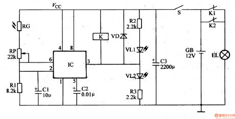
In the daytime, the photeresistor RG will have a low resistance value because of the light. IC's pin 2's and pin 6's voltages arehigher than 2Vcc/3. IC's pin 3 will output low level, which will make the relay K connected. Its normally open contactors K1 and K2 are both disconnected and the illumination EL is not illuminated.
When it is dark, RG will have a larger resistance value because of lack of light. IC's pin 2's and pin 6's voltages will become lower. When the voltage is lower than Vcc/3, IC's pin 3's low level will become high level which will make the relay K released. Its normally closed contactors K1 ,K2 are both connected. The illumination EL is illuminated. (View)
View full Circuit Diagram | Comments | Reading(529)
Light-Operated Streetlight (1)
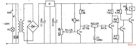
Published:2011/7/8 5:35:00 Author:Sue | Keyword: Light-Operated, Streetlight
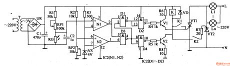
The 220v ac voltage will provide the light-operated circuit and trigger control circuit's IC1,IC2,K with +gV working voltage after it is reduced by T, rectificated by UR, filtrated by C1. The +9v voltage is also divided into four circuits. One will serve as electric supply detect sampling voltage after it is voltage divided by R2,RP2. One will provide N1's positivephaseinput terminal with light-operated signal voltage after it is voltage divided by R1,RP1,RG. One will provide N1's negative phase input terminal and N2's positive phase input terminal with 4V base voltage after it is voltage divided by R3,VS. Another one will provide V1 with working voltage after it is limited by R6.
In the daytime, RG has a low resistance value because of the light. N1's positive phase input terminal(IC1's pin 5)'s voltage is lower than that of negative phase input terminal(IC1's pin 4)'s, so it outputs low level.AND NOT GATE D1,D3 both output high level. D2,D4 both output low level.V1,V2 are disconnected. K is not connected and VT1,VT2 are disconnected. EL1-ELn are not illuminated. (View)
View full Circuit Diagram | Comments | Reading(527)
Light-Operated Streetlight (2)
Published:2011/7/8 5:51:00 Author:Sue | Keyword: Light-Operated Streetlight
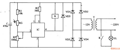
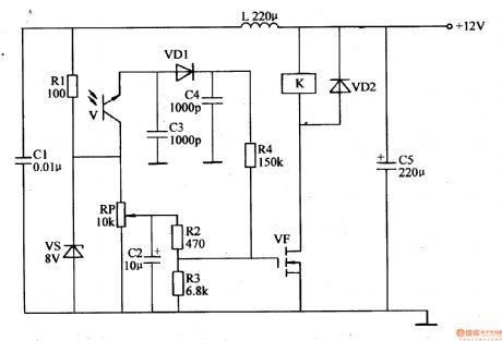
The 220V ac voltage will provide the light-operated circuit with +12V working power after it is reduced by T, rectificated by VD1-VD4, filtrated by C.
In the daytime, RG will have a low resistance value because of the light, which will make IC's pin2 and pin 4(output terminal) output high level. Its inner electronic switch is disconnected and K is disconnected. The illumination EL is not illuminated.
In the evening, RG will have a high resistance value because of lack of light, which will make IC's pin 2 output low level. Its inner electronic switch is connected and EL is illuminated.
By adjusting RP's resistance value, the light-operated sensitivity will be changed. (View)
View full Circuit Diagram | Comments | Reading(523)
Light-Operated Streetlight (3)
Published:2011/7/8 5:19:00 Author:Sue | Keyword: Light-Operated, Streetlight
The 220V voltage will provide the light-operated circuit with +12V voltage after it is reduced by T, rectificated by UR, filtrated by C1, stablized by IC.
In the daytime, RG will have a low resistance value because of the light. V1,V3 are connected. v2,v4 are disconnected. K,KM don't work and the streetlight is not illuminated.
In the evening, RG will have a high resistance value and V1,V3 are disconnected. V2 and V4 are connected. K, KM will be connected. The streetlight is illuminated.
By adjusting potentiometer RP1's resistance value, the illuminations can be on and off in the proper light. (View)
View full Circuit Diagram | Comments | Reading(523)
Light-Operated Streetlight (4)
Published:2011/7/8 6:03:00 Author:Sue | Keyword: Light-Operated, Streetlight
In the daytime, the photoresistor RG will have a low resistance value because of the light. IC's pin 2 and pin 6 will output high level(higher than 2Vcc/3). Its pin 3 will output low level. VL is not illuminated and VT is disconnected. The illumination EL is not illuminated.
In the evening, RG's resistance value will be higher because of the light is becoming less. IC's pin 2 and pin 6 will have a lower voltage. When IC's pin 2's voltage is lower than Vcc/3, IC's inner trigger will be reversed. Its pin 3 outputs high level. VL is illuminated. VT is connected and the illumination power is on. EL is illuminated. (View)
View full Circuit Diagram | Comments | Reading(442)
Light-Operated Streetlight (5)
Published:2011/7/8 6:00:00 Author:Sue | Keyword: Light-Operated, Streetlight
The light-operated circuit consists of light-operated transistor V, diodes VD1,VD2, capacitor C2-C4, field effect transistor VF, potentiometer RP, resistor R2-R4 and relay K.
In the daytime, V has a low resistance value because of the light and V is disconnected. VF is connected. K is connected. The working power is cut off by its normally closed contactor and the streetlight is not illuminated. In the evening, V has a high resistance value and VF is disconnected. K is released. The working power is connected by its normally closed contactor, then the streetlight will be illuminated.
By adjusting RP's resistance value, the light-operated sensitivity can be changed. (View)
View full Circuit Diagram | Comments | Reading(632)
Light-Operated Streetlight (6)
Published:2011/7/8 5:53:00 Author:Sue | Keyword: Light-Operated, Streetlight
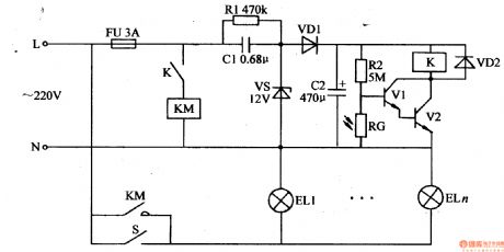
The light-operated circuit consists of photoresistor RG, resistor R2, transistors V1,V2, relay K, ac contactor KM, diode VD2 and manual switch S.
The 220v ac voltage will provide the light-operated circuit with 12v working voltage after it is reduced by C1, stablized by VS, rectificated by VD1, filtrated by C2.
In the daytime, RG will have a low resistance value which will make V1,V2 disconnected. K, KM are released. K and KM are disconnected. EL1-ELn are not illuminated.
When it is dark, RG will have a higher resistance value which will make V1,V2 connected. K is connected and its normally open switch is connected. KM is connected and EL1-ELn are illuminated. (View)
View full Circuit Diagram | Comments | Reading(597)
Light-Operated Streetlight (7)
Published:2011/7/8 5:47:00 Author:Sue | Keyword: Light-Operated, Streetlight
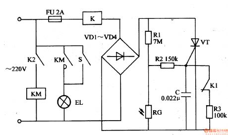
The 220v ac voltage will become direct current voltageafter it is reduced by K, rectificated by VD1-VD4. One circuit will be put on VT's positive electrode. The other circuit will provide VT's gate electrode with trigger voltage through R2 after it is voltage divided by R1,RG.
In the daytime, RG will have a low resistance value because of the light. C's voltage is low, so VT is not connected. K and KM are not connected. Illuminations EL1-ELn are not illuminated.
When it is dark, RG has a high resistance value which will make C have a higher voltage. VT will be connected and K is connected. Its normally closed contactor K1 is disconnected, while its normally open contactor K2 is connected. KM is connected. KM's normally open contactor will make EL1-ELn's working power connected. EL1-ELn will be illuminated. (View)
View full Circuit Diagram | Comments | Reading(528)
Light-Operated Streetlight (13)
Published:2011/7/5 23:37:00 Author:Sue | Keyword: Light-Operated, Streetlight
In the evening, RG has a high resistance value because of lack of light. A's electric potential becomes higher and higher. IC1's pin 6's voltage is higher than 2Vcc/3. Its pin 3 outputs low level. VD1,VD3 and V are disconnected and VD2 is connected. B will have high level and IC2's pin 6's voltage is higher than 2Vcc/3 too. IC2's pin 3 outputs low level which will make VT connected. EL is illuminated. At the same time, C3 is discharged slowly through R6,R7 and RP2. Then IC2's pin 2's voltage becomes lower and lower. Time delay is about 4.5-6.5h. When IC2's pin2's voltage is lower than Vcc/3, its pin 3 outputs high level again which makes VT disconnected and EL is off. (View)
View full Circuit Diagram | Comments | Reading(388)
| Pages:1567/2234 At 2015611562156315641565156615671568156915701571157215731574157515761577157815791580Under 20 |
Circuit Categories
power supply circuit
Amplifier Circuit
Basic Circuit
LED and Light Circuit
Sensor Circuit
Signal Processing
Electrical Equipment Circuit
Control Circuit
Remote Control Circuit
A/D-D/A Converter Circuit
Audio Circuit
Measuring and Test Circuit
Communication Circuit
Computer-Related Circuit
555 Circuit
Automotive Circuit
Repairing Circuit