
Circuit Diagram
Index 1568
Fluorescent Lamp Electronic Ballast (5)
Published:2011/7/7 5:08:00 Author:Sue | Keyword: Fluorescent Lamp, Electronic, Ballast
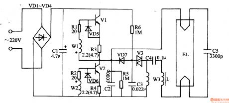
When the power is on, the 220v ac voltage will provide the high frequency oscillate circuit with 300v direct current working voltage afterit is rectificated by VD1-VD4, filtrated by C1. C3 is charged by R6 and when C3's voltage reaches V3's breakover voltage, VS will be connected quickly. C3 begins to be discharged on T's winding W3 through V3. Then V1 and V2 will be connected intermittently under the coupling of T. The high frequency oscillator will begin to work.After the oscillator begins to work, C2 will generate a high frequent alternating voltage which is similar to sine wave and the voltage will be provided to EL through C4,L1. When C5's voltage reaches EL's discharging voltage, EL will be illuminated. (View)
View full Circuit Diagram | Comments | Reading(7968)
CH50212 Single-Chip Micro-Computer Integrated Circuit
Published:2011/7/9 2:28:00 Author:Robert | Keyword: Single-Chip, Micro-Computer, Integrated
The CH50212 is a single-chip micro-computer control IC which is widely used in many kinds of Changhong series players.
1.Its functional features.
The CH50212 IC's internal part is mainly made up of I(2)C bus circuit, clock oscillation circuit, reset circuit, system control data input/output interface circuit, reading/writing control circuit and so on.
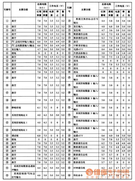
2.Its pin's function and data.
The CH50212 IC uses 64-pin square package and its pin's function and data is shown in table 1.
The table 1 shows the CH50212 IC's pin's function and data.
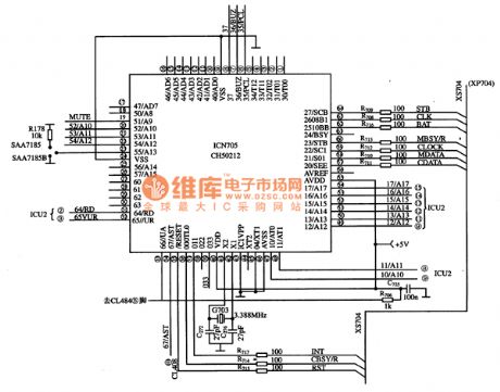
3.Typical application circuit. The system control typical application circuit composed of CH50212 IC is shown in picture 1.
The picture 1 shows the CH50212 IC's typical application circuit. (View)
View full Circuit Diagram | Comments | Reading(620)
BMW7 series 740i E38DWA IV anti-theft system circuit (2)
Published:2011/7/8 5:50:00 Author:Christina | Keyword: BMW7 series, 740i, anti-theft system
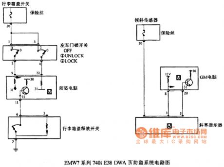
BMW7 series 740i E38DWA IV anti-theft system circuit (2)
(View)
View full Circuit Diagram | Comments | Reading(415)
Over-voltage protection circuit uses the two-way trigger diode to trigger the two-way thyristor
Published:2011/7/8 5:50:00 Author:Christina | Keyword: Over-voltage, protection, two-way, trigger diode, two-way thyristor
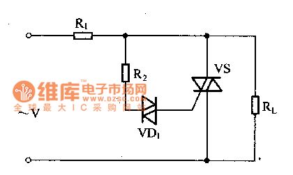
The over-voltage protection circuit which is composed of the two-way trigger diode and the two-way thyristor is as shown in figure 1. When the voltage is normal, the voltage of the two-way trigger diode is smaller than the turning voltage, the VD1 will not conduct, the two-way thyristor is in the cut-off state, the load RL can get the power. When the power supply transient voltage is the over voltage, the voltage which is added on the two-way trigger diode is larger than the tuning voltage, so VD1 conducts and triggers the two-way thyristor to conduct it, so the load RL is away from the overvoltage damage.
Figure 1 The over-voltage protection circuit
(View)
View full Circuit Diagram | Comments | Reading(1517)
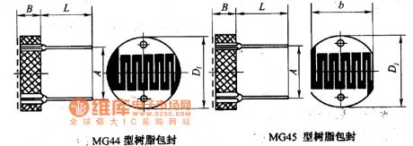
MG45 and MG44 resin package circuit
Published:2011/7/8 5:50:00 Author:Christina | Keyword: resin package
View full Circuit Diagram | Comments | Reading(565)
Unijunction semiconductor tube trigger circuit
Published:2011/7/8 5:49:00 Author:Christina | Keyword: Unijunction, semiconductor tube, trigger circuit

This device can be used in wide range of applications, the trigger pulse is mainly produced by the unijunction semiconductor tube.
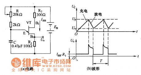
By using the characteristics of the unijunction semiconductor tube and the RC charging and discharging circuit, we can form the oscilation circuit, this circuit is as shown in the figure. The VT is the unijunction semiconductor tube.
The waveform and the oscillation circuit of the unijunction semiconductor tubeThe circuit in the figure uses the bridge rectifier and it also uses the same power supply with the main circuit to achieve the synchronization. The URL is the voltage of load.
Unijunction semiconductor tube trigger circuit
The waveform of the power supply which is rectified by the bridge rectifier circuit is as shown in the figure, it supplies the synchronous power to the trigger circuit. When the AC power supply voltage crosses zero, the UZ voltage is zero too, at this time the voltage between the two base electrodes of the VT is UBB=0, the peak point voltage Up of the VT is about zero, the VT and E-B conduct, the capacitor C will discharge all of the electric charge quickly. (View)
View full Circuit Diagram | Comments | Reading(695)
CH238 Accompaniment Control Integrated Circuit
Published:2011/7/9 2:52:00 Author:Robert | Keyword: Accompaniment, Control, Integrated
The CH238 is a accompaniment control IC which is widely used in many brands of electronic musical instruments such as electronic organ and so on.
1.Its functional features.
The CH238 IC uses CMOS production technology so that it has the a CMOS feature. It has internal two parts which are disintegration chord accompaniment control and bass chord accompaniment control. Its essence is a accompaniment pattern control memory (ROM) which is designed according to the need of music. It can make up 6 kinds of combinations of the disintegration chord and bass chord to be chosen.
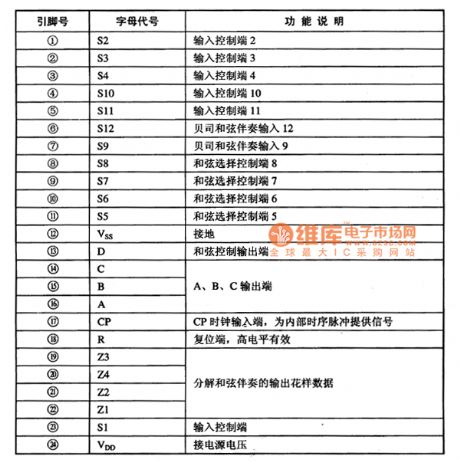
2.Its pin's function.
The CH238 IC uses 24-pin dual plastic inline package and its pin's function is shown in table 1.
The table 1 shows the CH238's pin's function. (View)
View full Circuit Diagram | Comments | Reading(580)
Output current expanding circuit
Published:2011/7/8 5:49:00 Author:Christina | Keyword: Output current, expanding
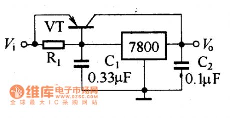
When the needed current is larger than the maximum output current of the voltage stabilizer, you can expand the output current by using the high-power transistor, the circuit is as shown in the figure.
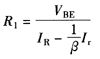
In this figure, VT is the high-power semiconductor transistor, you need to choose the semiconductor transistor according to the maximum current which needs to be expanded. The resistance value of the R1 can be decided by this formula:
In the formula:
VBE--Positive pressure drop of transistor BE, the Ge transistor is 0.3V, the Silicon transistor is 0.7V;IR--Output current of the three-port integrated voltage stabilizer;Ir--Output current of the power transistor, Ir=i. -iR.β--Amplification coefficient of the power transistor.
The circuit uses the powertransistor to expend the output current (View)
View full Circuit Diagram | Comments | Reading(716)
CH05002 Single-Chip Micro-Computer Integrated Circuit
Published:2011/7/9 2:39:00 Author:Robert | Keyword: Single-Chip, Micro-Computer, Integrated

The CH05002 is a single-chip micro-computer IC which is widely used in Changhong series large-screen picture-in-picture digital color TV sets.
1.Its functional features.
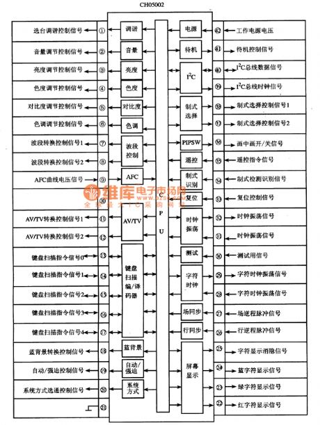
The CH05002 IC's internal part is mainly made up of central processing unit (CPU), clock oscillation circuit (main clock and display clock), reset control circuit, remote-control command signal processing circuit, keyboard scanning coding/decoding circuit, I(2)C bus control circuit, standby.starting control circuit, testing circuit, picture-in-picture control circuit and other some control and auxiliary function circuits. Its internal circuit diagram and signal flowing is shown in picture 1.
The picture 1 shows the CH05002 IC's internal circuit diagram and signal flowing.
2.Its pin's function and data.
The CH05002 IC uses 42-pin dual package and its pin's function and data is listed in table 1.
The table 1 shows the CH05002 IC's pin's function and data. (View)
View full Circuit Diagram | Comments | Reading(557)
LCD DC/DC Convertor Circuit
Published:2011/7/8 1:10:00 Author:Joyce | Keyword: LCD, DC/DC, Convertor
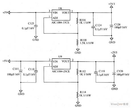
AOC LM729 LCD DC/DC convertor circuit is as shown in the following figure.
As we can see from the graph, the DC/DC converter is quite simple. Its working process is shown as follows:
A + 5 V voltage provided by switching power supply circuit will output a 3.3 V voltage through foot 2 of LDO stabilizer U8 (AIC1084-33 CE) after being stabilized by it. The output mainly supplies power for the driver board, the LCD panel and ect; A + 5 V voltage provided by switching power supply circuit will output a 2.5 V voltage through foot 2 of LDO stabilizer U9 (AIC1084-25 CE) after being stabilized by it. The output mainly supplies power for the driver board circuit. (View)
View full Circuit Diagram | Comments | Reading(1000)
The Ni-Cd battery charging circuit
Published:2011/7/8 5:46:00 Author:Christina | Keyword: Ni-Cd, battery, charging circuit
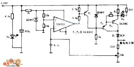
This circuit uses the automatic control and constant current charging methods, and the nominal voltage of thecharged battery is 10V, the charging termination voltage is 12V. The constant-current power supply is composed of the T2,T3 and the related components, the current value is about 4.8V/R1. Diode D1 can prevent the battery discharging when the AC power cuts off or the rectifier circuit failure. LM311 is the comparator, once the comparator is charged to the set value, it will output the low level voltage, the T1 is saturated and turns on, T2 constant-current power supply stops working, the charging process stops.
When you are charging, the LED D2 turns on; D3 can be used as the power indicator.
(View)
View full Circuit Diagram | Comments | Reading(908)
μA741 direct coupling audio power amplifition circuit
Published:2011/7/7 1:15:00 Author:chopper | Keyword: direct, coupling, audio power, amplifition
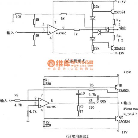
The picture shows direct coupling audio power amplifition circuit.It has two pratical methods of audio power amplifier formed by integrated op-amp.The first practical form is shown in (a).And the structure of the circuit is to add the complementary symmetry emitter follower to the output end of op-amp, and this form is simple,easy to use,but power usage is low.Figure (a) tells that the emitters of two dynatrons are connected with RE (1.2Ω) in series, whose role is to implement over-current protection to power amplifier dynatron. (View)
View full Circuit Diagram | Comments | Reading(1551)
AE1169-Equipped Enhanced Code Lock Circuit
Published:2011/6/30 4:18:00 Author:Joyce | Keyword: AE1169-Equipped, Enhanced, Code Lock
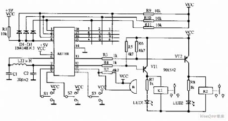
When the button of an AE1168-equipped enhanced code lock is pressed, AE1168 will locate the corresponding button through keyboard scan. And it will control alarm relay K1, relay K2 after being analysed by internal logic according to the state of S1, S2, S3.The circuit uses 12-bit keyboard with the * key signifying confirmation ; the # key signifying clear.Tf oneinputs the wrong password out of carelessness,as long as the * key has not been pressed, one can clickthe button # to clear the wrong code. By switching S1, S2, S3 , we can confirm collectively or by oneself. (View)
View full Circuit Diagram | Comments | Reading(810)
economic light of voltage reduced capacitance circuit
Published:2011/6/28 3:13:00 Author:chopper | Keyword: economic light, voltage reduced capacitance
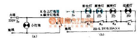
This circuit is simple but practical.For example:(a)When K is close,impact current will be shorted by K,and bulb will go out.When K is open,the bulb will light.The control method of K is opposite to the normal method.(b)This picture describes several small bulbs in seriesfor lighting use.The capacitance is used to compensate power,and eliminate the outside interference.When we use this circuit,we must be careful and pay more attention.
(View)
View full Circuit Diagram | Comments | Reading(482)
gain control circuit with programmable gain amplifier
Published:2011/6/12 21:37:00 Author:chopper | Keyword: gain control, programmable gain amplifier
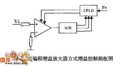
This mode can achieve gain control by adopting the existing programmable gain amplifier integrated circuit directly.The diagram of circuitous philosophy is shown as picture 4.ICs at thisfield are PGA103,PGA204,AD526,AD620,THS7001 and so on andthe gain control only has fixed levels.Some magnifications are 1, 2, 4, 8, 16 times,and some are 1, 2, 4, 8, 16 times.The way setting the gain control are resistance setup,pin setup,and software setup.
(View)
View full Circuit Diagram | Comments | Reading(574)
Multiple Music Doorbell Circuit
Published:2011/7/8 1:09:00 Author:Joyce | Keyword: Multiple Music , Doorbell
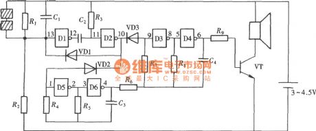
The music doorbell as shown in the figure is composed of several musical circuit. When the visitors press the doorbell , they can hear constantly changing music , which will, on one hand, alleviate the visitors` anxiety; on the other hand, provide the host with enough time to open the door while stops his/her current work. As shown in the figure, the circuit is composed of a doorbell triggering circuit, multiple music automatically switch circuit and several musicals. (View)
View full Circuit Diagram | Comments | Reading(1288)
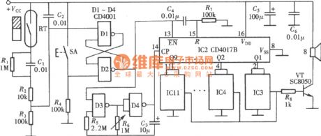
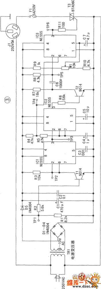
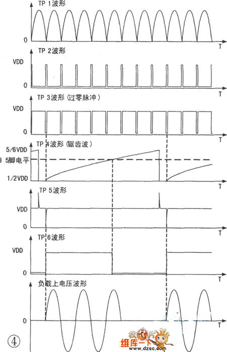
Principle of Silicon Control Zero Passage Trigger Circuit
Published:2011/6/12 21:37:00 Author:chopper | Keyword: Silicon Control, Zero Passage Trigger
View full Circuit Diagram | Comments | Reading(645)
Touch Diphonia Doorbell Circuit
Published:2011/7/8 8:37:00 Author:Joyce | Keyword: Touch, Diphonia , Doorbell
As shown in the figure, the touch daphnia doorbell does not have a button, but has a pair of touch slices as the starting switch. When one’s hand touches the slice, a certain amount of high level gained by the slice from the power source through the human resistance will start the circuit, which is as shown in the figure. The circuit is composed by a CD4069 of six inverters. Two of the gates constitute start-and-stop circuit, two gates form an audio oscillator, and the rest two doors compose a rhythm oscillator of the audio oscillator (View)
View full Circuit Diagram | Comments | Reading(759)
musical E-bell circuit
Published:2011/6/12 21:36:00 Author:chopper | Keyword: musical E-bell
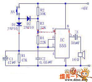
The following picture is a circuit of doorbell which can send out a sound like ding,dong .It is constituted of a time-base circuit integrated package and peripheral cells.The bell has a graceful and vivid tone,and it is easy and cheap to set up .A 6V laminated battery can be used over 3 months.Its electric power consumption is very low.The IC in the picture is time-base circuit integrated package 555 which forms astable multivibrator.Press the AN(which is set up on the door),the oscillator works, and the oscillating frequency is about 700Hz,and the speaker sends out ding .
(View)
View full Circuit Diagram | Comments | Reading(1923)
absolute value amplifier with polarity detector circuit
Published:2011/6/12 21:36:00 Author:chopper | Keyword: absolute value amplifier, polarity detector
View full Circuit Diagram | Comments | Reading(580)
| Pages:1568/2234 At 2015611562156315641565156615671568156915701571157215731574157515761577157815791580Under 20 |
Circuit Categories
power supply circuit
Amplifier Circuit
Basic Circuit
LED and Light Circuit
Sensor Circuit
Signal Processing
Electrical Equipment Circuit
Control Circuit
Remote Control Circuit
A/D-D/A Converter Circuit
Audio Circuit
Measuring and Test Circuit
Communication Circuit
Computer-Related Circuit
555 Circuit
Automotive Circuit
Repairing Circuit