
Circuit Diagram
Index 1571
Code hopping radio control circuit TR1300/1315
Published:2011/7/8 5:58:00 Author:TaoXi | Keyword: Code hopping, radio control
The radio transmission circuit:
The remote control receiver demodulation and decoding output circuit:
(View)
View full Circuit Diagram | Comments | Reading(906)
Transceiver module composed of the wireless remote control fan governor RCM1A/RCM1B
Published:2011/7/8 5:59:00 Author:TaoXi | Keyword: Transceiver module, wireless remote control, fan governor
This governor has three gears of wind speed: strong, middle and weak, you can control it by the wireless remote control method or touch the switch, and this governor can be used to transform the touch mode ceiling fans and electric fans. You can connect it to the electric fan motor after the installation is complete, for the motor with the speed shaft head, you can connect it according to the above figure. For the motor with the speed reactor, you can connect it according to the figure.
(View)
View full Circuit Diagram | Comments | Reading(988)
Transceiver module composed of the remote control voice doorbell RCMlA/RCMlB
Published:2011/7/8 5:59:00 Author:TaoXi | Keyword: Transceiver module, remote control, voice doorbell
The remote control doorbell saves the wiring between the button and the doorbell, the installation position of the doorbell is very flexible and it is convenient. The voice integrated circuit can use the KD15 series of soft packaging integrated circuit. After the circuit is installed, you can use it immediately. when you are using it, you should make the receiver away from the big metal objects to avoid the influencing of the remote sensitivity.
(View)
View full Circuit Diagram | Comments | Reading(839)
TMPA8809 Multi-Function Super-Monolithic Integrated Circuit Diagram
Published:2011/7/10 6:09:00 Author:Vicky | Keyword: Multi-Function, Super-Monoli
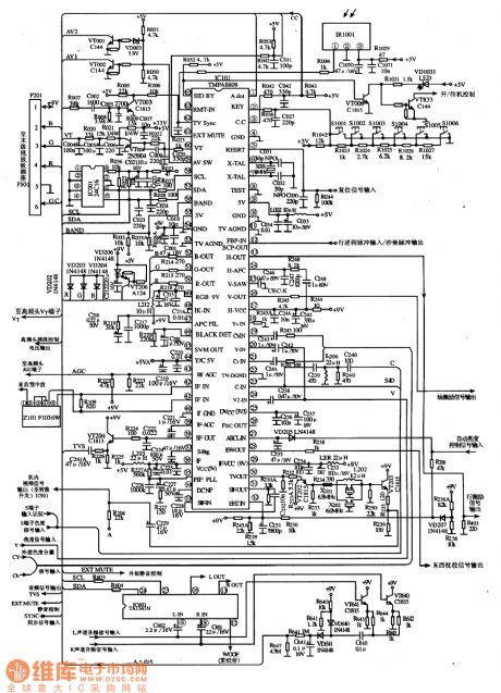
TypicalApplied Ciruict of IC TMPA8890
TMPA809 is a multi-function super-monolithic integrated circuit produced by Toshiba Corporation. It is used in domestic and imported color television set, such as Toshiba series large-screen color television set ,and Haier series large-screen color television set, as well as TCL series etc.
1 function features:
TMPA8809 integrated circuit includes control system micro computer circuit, TV signal processing, line scanning and field scanning small-signal processing circuit, teletext decorder circuit and some other auxiliary circuits.
2 function and feature of the pins
The pins of IC TMPA8809 adopt dual-in-line packages .
3 typical applied circuit
The above picture is a typical applied circuit diagram of TV signal processing and control system which is composed of TMPA8809 integrated circuit . (View)
View full Circuit Diagram | Comments | Reading(2643)
Temperature Measurement Circuit (3) of Thermistance
Published:2011/7/8 0:05:00 Author:Michel | Keyword: Thermistance, Temperature Measurement Circuit
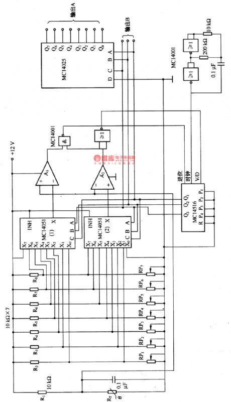
The temperature measuremnet circuit composed of thermistance etc. is shown as above. The temperature range and switch points of thermistors measurement are decided firstly.That's to say, temperature and thermistors corresponding resistance (R) are set according to the sequence of R (RPl),R2 to R(RP7), R8 (high temperature to low temperature).MC14516 is counter and the counter stop counting if the thermistance is in setting temperature range.The counting value outputs via B port and the octal signal outputs via A end. (View)
View full Circuit Diagram | Comments | Reading(1218)
Sawtooth Wave Generating Circuit Synchronous with Industrial Frequency Power
Published:2011/7/8 22:52:00 Author:Michel | Keyword: Industrial Frequency, Sawtooth Wave, Generating Circuit
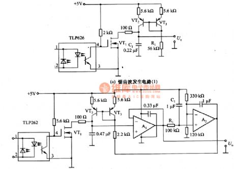
This figure is sawtooth wave generating circuit synchronous with industrial frequency power.6-67(a) is awtooth wave generating circuit synchronous with industrial frequency power composed of current mirror.R1 is used to adjust the slope of the waveform.Voltgae two ports of C1 output in original sawtooth wave way so the high impedance circuit is connected.
The picture (b) is sawtooth wave generating circuit whose amplitude is constant when the input frequency is changed.R1 and C1 make sawtooth wave smooth, it makes the feedback on the current mirror composed of VT2 and VT3 after A2's comparasion.This circuit fits for industrial frequency,50HZ/60HZ and air or aviation equipment's 400HZ and its corresponding scope is 40 to 400 HZ and its frequency range is very wide. (View)
View full Circuit Diagram | Comments | Reading(685)
10HZ ~100 kHZ White and Pink Noise Generating Circuit
Published:2011/7/9 1:04:00 Author:Michel

The picture is 10HZ~ 100kHZ white and pink noise generating circuit.This is a generating circuit who has 10HZ~100kHZ plain frequency characteristics white noise and -3 dB/oct spectrum pink noise. If white noise is put into the sample,the output signal spectrum is measured and the transmission properties of the sample can be obtained.When the measured
system contains mechanical system,there will be resonance between the measured system and a particular frequency if sine wave scans measured system,which will destroy the sample.Thus usually,white noise is used.In the audio measurement noise signal is also used and when measured system contains the speaker, the power is high if white noise is used and it's high
frequency. (View)
View full Circuit Diagram | Comments | Reading(2566)
Simple Temperature Measurement Circuit of Thermistor
Published:2011/7/9 21:58:00 Author:Michel | Keyword: Thermistor, Temperature Measurement Circuit
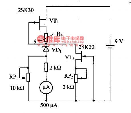
This picture is a simple temperature measurement circuit composed of thermistor.In the circuit,VT1 is self-biased constant current source circuit and it provides constant current for thermistors RT. The measured temperature is standed for 500μA and measuring temperature rage is 0一5O℃.Measuring method:2.538kΩ ordinary resistance substitutes for RT and RP1 is adjusted to make the header instruction become largest and RP2 is regulated to make the header instruction become zero.Then 0.4422 k Ω ordinary resistance substitutes for RT and RP1 is regulated to make the header instruction become full scale.Please adjust it again and again until we get the satisfying value. (View)
View full Circuit Diagram | Comments | Reading(1187)
White Nosie Generator Circuit of Shift Register and Exclusive-OR Gate
Published:2011/7/9 22:28:00 Author:Michel | Keyword: Shift Register, Exclusive-OR Gate, White Nosie, Generator Circuit
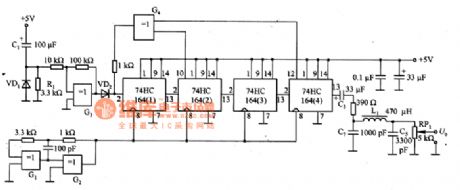
The picture is the white noise generator circuit of shift register and exclusive-or gate.R1 and C1 constitute differential circuit and the circuit enters work state when the switch is turned on.R2, R3 and G3 constitute schmidt trigger circuit.Feet 13 output voltgae of 74HC164(4) is binary signal and the low pass filter composed of L1, C5 and C7 makes amplitude probability density function become normal distribution white noise,namely,Gaussian noise.The cut-off frequency of the low pass filter is enough lower than clock frequency (about 3 MHZ).RP1 is used to adjust and outputs U PWL. (View)
View full Circuit Diagram | Comments | Reading(1996)
Function Generator Circuit of 74HCUO4
Published:2011/7/9 22:44:00 Author:Michel | Keyword: Function Generator Circuit
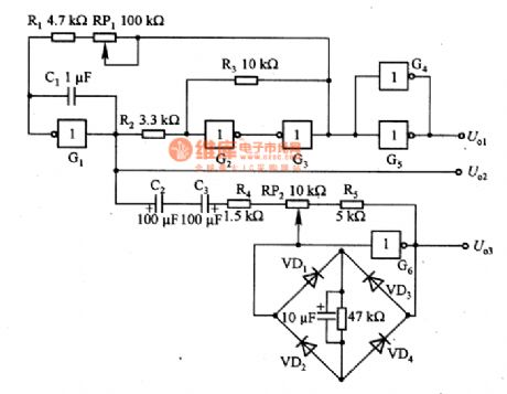
The picture is function generator circuit of 74HCUO4 and G1~G6 is 74HCUO4 inside circuit.This circuit can also output sine wave, rectangular wave and triangle wave at the same time.G1 and C1 constitute Mueller integral circuit and R2, R3, G2 and G3 constitute Schmidt circuit.Output of Schmidt circuit returns to input of miller integral through RP1 and it becomes rectangle wave oscillator. RP1 is used for oscillation frequency adjustment.RP2,R4,R5 and G6 constitute linear inverse amplifier. VD1 ~ VD4 make of diode bridge road and cut top of the triangle wave and turn the triangle wave to sine wave.RP2 adjusts sine wave distortion rate to the minimum value.U.1 outputs rectangle wave,U.2 outputs triangle wave and U.3 outputs sine wave. (View)
View full Circuit Diagram | Comments | Reading(1509)
Temperature Monitoring Circuit of Transistor Temperature Sensor
Published:2011/7/10 19:15:00 Author:Michel | Keyword: Transistor Temperature Sensor, Temperature Monitoring Circuit
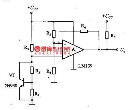
This figure is monitoring circuit of transistor temperature sensor temperature.In the circuit,VT1 is used as temperature snesor,it
adopts the -2·2mV/℃ temperature coefficient of silicon transistors base-emitter voltage and the temperature range is
-65一15O℃. A1 is comparator circuit and its output is U。and is connected with corresponding alarm system.R3 and R4 determine temperature setting value and the warner sounds when the present temperature exceeds setting value. (View)
View full Circuit Diagram | Comments | Reading(3901)
Electronic Thermometer of Transistor Temperature Sensor
Published:2011/7/10 5:24:00 Author:Michel | Keyword: Transistor Temperature Sensor, Electronic Thermometer
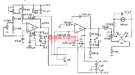
The figure is electronic thermometer of the transistor temperature sensor.In the circuit VT1 is the transistor temperature sensor and its measuring range is -30一100℃.The circuit is composed of DC amplifier and benchmark voltage circuit, Al constitutes benchmark voltage circuit and A2 constitutes DC amplifier. S1 is used for temperature measuring range and it's 0一100℃ when 1 is swithced and it's 0一5℃ when 2 is switched.S2 is used for the header polarity switch. (View)
View full Circuit Diagram | Comments | Reading(1479)
Portable Silicon Voltage Stabilizing Tube Regulation Circuit
Published:2011/7/7 22:57:00 Author:Michel
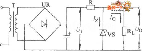
The portable silicon voltage stabilizing tube regulation circuit is shown as above.Welcome to download the circuit and the information is from www.dzsc.com. (View)
View full Circuit Diagram | Comments | Reading(559)
A Simple Stabilized Voltage Circuit with Overcurrent Protection Function
Published:2011/7/7 22:46:00 Author:Michel | Keyword: Stabilized Voltage Circuit, Overcurrent Protection
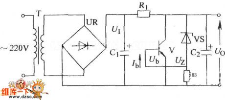
The stabilized voltage circuit with overcurrent protection function is shown as above.Welcome to download the circuit and this information is from www.dzsc.com. (View)
View full Circuit Diagram | Comments | Reading(542)
DS18B20 and 51 Single Chip AT89C2051 Interface Circuit
Published:2011/7/7 22:28:00 Author:Michel | Keyword: 51 Single Chip, Interface Circuit
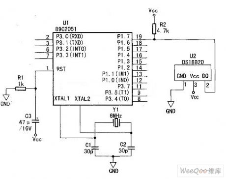
The DS18B20 and 51 single chip AT89C2051 interface circuit is shown as abvoe.The P1.7 mouth line of AT89C2051 is connected to pins 2 data side of DS18820 after being pulled.The pin 1 connects to low power port and pin 3 connects to +5V power supply end. (View)
View full Circuit Diagram | Comments | Reading(2758)
Contrast between SMT Telephone Processing Test Instruments 8960 and CMU200
Published:2011/6/25 8:04:00 Author:Michel | Keyword: Contrast, SMT Telephone, Processing Test Instruments
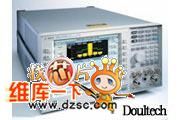
Part No.:8960/E5515CProduction Instructions
It is usedin largeproduction test of mobile phone production processing.
In the mass production of the mobile phone,test throughput and test pass rate are key problems considering of production.Agilent 8960 series 10 wireless communication test device provides the advantageous conditions of taking part in competition immediately for mobile phone producers.The 8960 series 10 test device provides rapid, accurate and repeatable,multiform ability, easy programming and flexible system structure.For phone manufacturers, , it is benificial to reducing test cost and increasing production. (View)
View full Circuit Diagram | Comments | Reading(874)
Basic Complementary Symmetry OTL Power Amplifier Circuit
Published:2011/6/25 7:19:00 Author:Michel | Keyword: Complementary, Symmetry, OTL Power, Amplifier Circuit
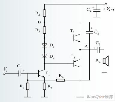
OTL is the English abbreviation of Output Transformer Less which means the transformer without output.OTL power amplifier is the power amplifier circuit that has not output coupling .OTL power amplifier mostly uses complementary and push-pull output level circuit.
The aboved picture is complementary symmetric OTL power amplifier circuit.T2 is a NPN power transistor,T3 is a PNP transistor and they constitutes complementary and push-pull output tube.T1 is voltage amplifier incentive tube.The signal is amplified in T1 after C1 coupling and its positive half cycle of signal which is generated by 1 collector makes T2 conduct.Its negative half cycle makes T3 conduct and the amplified signal outputs to speaker via capacitance C3.
(View)
View full Circuit Diagram | Comments | Reading(3296)
MIC2298 Driving LED Circuit
Published:2011/6/27 23:38:00 Author:Michel | Keyword: Driving LED Circuit
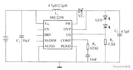
Micrellnc introduced the most powerful volume and function LED driver, MIC2298 which is used in portable electronic equipment.This device is a 7 W efficient boost DC/DC converter with small 3 mm x 3 mm of MLF form encapsulation.MlC2298 is designed for mobile phones,personal,digital assistant (PDA) and digital camera flash, flashlight lighting.
MIC2298 can ensure 3.5A conversing current.Its white LED brightness can realize dynamic control via brightness setting,pins voltage or pulse width adjustment (PWM) signal. The circuit's efficiency is over 86% when it works in fixed conversion frequency. (View)
View full Circuit Diagram | Comments | Reading(678)
LT3486 Automobible LED Driver Circuit
Published:2011/6/28 2:19:00 Author:Michel | Keyword: Automobible, LED Driver, Circuit
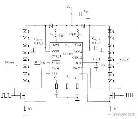
LED's advantages are as follows when it is used in automobile central high brake lights (CHMSL).It reaches setting brightness faster and has longer service life with higher efficiency.And what's more, the very tiny red LED array is more easily for design and installation.LED can reach a setting brightness in less than 1 ms, so that driver behind the car can see the brake lights faster,which lessen rear-end collision.On contrast,traditional bulbs can get the setting brightness in 200ms.Compared with incandescent lamp, LED lamp power consumption can reduce to as high as 80%, which reduces the car fuel consumption.
(View)
View full Circuit Diagram | Comments | Reading(932)
PWM Brightness Adjusting Circuit
Published:2011/6/28 1:59:00 Author:Michel | Keyword: PWM Brightness, Adjusting Circuit
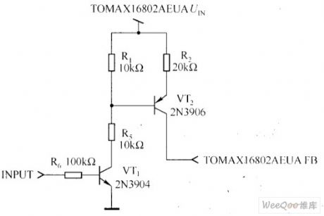
R1 and R2 are used to adjust to 29V.This is very useful when output end occurres incident opening.Output division voltage may rise ,which causes devices damage if there is division voltage devices.C1 and R5 are used to stablize voltage feedback loop.
The best way to control white LED brightness is to adjust white LED via a low frequency PWM pulse.The low frequency PWM pulse modulation method can make the white LED current keep stable current scale according to dutyfactor change and it can make LED light wavelengths keep constant in the adjustment range.PWM adjusting brightness circuit is shown as the aboved figure.
Picture:PWM Brightness Adjusting Circuit (View)
View full Circuit Diagram | Comments | Reading(791)
| Pages:1571/2234 At 2015611562156315641565156615671568156915701571157215731574157515761577157815791580Under 20 |
Circuit Categories
power supply circuit
Amplifier Circuit
Basic Circuit
LED and Light Circuit
Sensor Circuit
Signal Processing
Electrical Equipment Circuit
Control Circuit
Remote Control Circuit
A/D-D/A Converter Circuit
Audio Circuit
Measuring and Test Circuit
Communication Circuit
Computer-Related Circuit
555 Circuit
Automotive Circuit
Repairing Circuit