
Circuit Diagram
Index 1575
Motorcycle Gears Indicator (2)
Published:2011/7/10 6:08:00 Author:Sue | Keyword: Motorcycle, Gears, Indicator
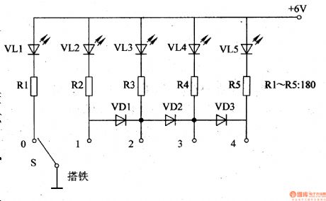
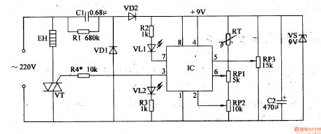
VL1 is neutral LED indicator. VL2-VL5 are gear 1-4 LED indicators respectively.
+V terminal is connected with the motorcycle's neutral LED's power.
When the switch is on, it is in neutral. Only the neutral LED indicator VL1 is illuminated. VL2-VL5 are not illuminated.
When the motorcycle is in gear 1, S's moving contact and 1 terminal are connected together. VL2 is illuminated while VL1 is off.
When the motorcycle is in gear 2, S's moving contact and 2 terminal are connected together. VD1 is connected. VL2 and VL3 are both illuminated.
When the motorcycle is in gear 3, S's moving contact and 3 terminal are connected together. VD1,VD2 are both connected. VL2-VL4 are all illuminated.
When the motorcycle is in gear 4, S's moving contact and 4 terminal are connected together. VD1-VD3 are all connected. VL2-VL5 are all illuminated. (View)
View full Circuit Diagram | Comments | Reading(1650)
Voltage / frequency conversion circuit composed of μPC157
Published:2011/7/7 6:45:00 Author:Lucas | Keyword: Voltage conversion , frequency conversion
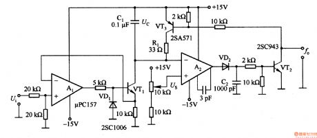
Al is used as voltage / current conversion circuit, which can convert 2V input voltage into lmA current charge for capacitor C1. As the voltage across the capacitor and changes in proportion with the time, so the voltage on the two ends of Cl will be equal the integral value of input voltage and time. A2 is the comparator. When Uc is lower than Us, the output jumps to near + l5V level, the diode VD2 is forward biased to make the transistor VT2 conduction. At the same time, the transistor VT3 is conduction, so the voltage of Uc resets in the constant of Cl and Rl.
(View)
View full Circuit Diagram | Comments | Reading(742)
Voltage / frequency conversion circuit composed of TA7506
Published:2011/7/7 5:45:00 Author:Lucas | Keyword: Voltage conversion , frequency conversion
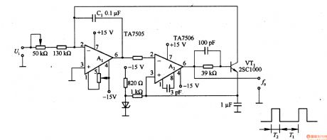
A1 integrates for the input voltage Ui, and the output voltage is applied also to the inverting input, which is compared with the same input reference voltage. If it is less than the reference voltage, A2 outputs high, VT1 turns on, then C1 begins to charge and discharge. The circuit can switch 0-lV voltage signal to 0-10Hz frequency signal.
(View)
View full Circuit Diagram | Comments | Reading(803)
Motorcycle Gears Indicator (1)
Published:2011/7/10 5:55:00 Author:Sue | Keyword: Motorcycle, Gears, Indicator
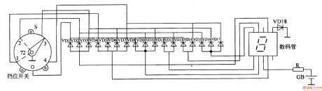
The storage battery GB's 12v(or 6v) voltage will be put on the digitalindicator after it is limited by R.
When the motorcycle is in neutral gear, S's moving contact and neutral contact are connected together, which will make the diode VD1,VD5,VD8,VD11,VD13 connected. The digital indicator indicates number 0 .
When the motorcycle is in gear 1, S's moving contact and gear 1 contact are connected together, which will make the diode VD4 connected. The digital indicator indicates number 1 .
When the motorcycle is in gear 2, S's moving contact and gear 2 contact are connected together, which will make the diode VD2,VD9,VD12,VD15 connected. The digital indicator indicates number 2 .
When the motorcycle is in gear 3, S's moving contact and gear 3 contact are connected together, which will make the diode VD3,VD6,VD10,VD16 connected. The digital indicator indicates number 3 .
When the motorcycle is in gear 4, S's moving contact and gear 4 contact are connected together, which will make the diode VD7,VD14,VD17 connected. The digital indicator indicates number 4 . (View)
View full Circuit Diagram | Comments | Reading(2554)
Voltage / frequency conversion circuit composed of FET
Published:2011/7/7 6:00:00 Author:Lucas | Keyword: Voltageconversion, frequency conversion , FET
In the T2 period, VTl turns on as the Cl discharge circuit to get a good conversion features. VT3 and VDz2 form the constant current source circuit, which can provide constant current power supply for VDz1. The circuit can switch 0 to -lV voltage signal into 0-10Hz frequency signal.
(View)
View full Circuit Diagram | Comments | Reading(696)
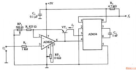
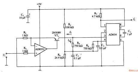
Voltage / frequency conversion circuit composed of LM331
Published:2011/7/7 6:06:00 Author:Lucas | Keyword: Voltage conversion , frequency conversion
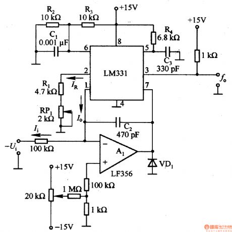
LM331 is the single voltage / frequency conversion IC within 1.9 v reference voltage, current switch, comparator and flip-flop, etc. In order to expand the range, the circuit is added A1 op amp. The reference current IR is decided by (Rl + R (RPl)), as the internal reference voltage is 1.9 V, IR = l · 9V / (Rl + R (RPl)), the usual range is 100 to 500μA. In addition, the current average value of the current switch output (pin 1) end is I. For the internal chip charge-discharge circuit, when the charging voltage reaches 2A as the supply voltage, the circuit is reset.
(View)
View full Circuit Diagram | Comments | Reading(4254)
The basic voltage/frequency conversion circuit composed of transistor
Published:2011/7/7 4:25:00 Author:Lucas | Keyword: basic , voltage conversion, frequency conversion , transistor
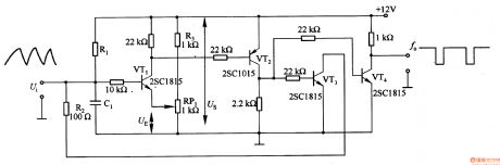
In the circuit, the RlC1 time constant and timing time of control comparator VT1 output are decided by changing set voltage UE. When VTl is turned on, VT2 and VT3 are turned on, then the integration capacitor C1 begins to discharge. R2 can adjust the discharge time constant. When set voltage UE is small, the oscillation frequency increases. In the circuit, VTl, VT3 and VT4 use 2SCl815 or 2SC945, VT2 uses 2SAlO15 or 2SA952.
(View)
View full Circuit Diagram | Comments | Reading(906)
Motorcycle Speed Indicator (3)
Published:2011/7/9 6:31:00 Author:Sue | Keyword: Motorcycle, Speed Indicator
The voltage which is generated by alternator will be put on LED VL1-VL8's positive electrode which will serve as display working power after it is limited by R1, rectificated by VD, filtrated by C1. One circuit will provide the operational amplifier N1-N8's inverting input terminals with sampling voltage after it is voltage divided by R2,R3. The other circuit will provide IC2,IC3 with working voltage after it is stablized by IC1. The +9v voltage also provide N1-N8's voltage input terminals with base voltage after it is voltage divided by RP1,R4-R10,RP2.
The motorcycle's speedis proportionate tothe alternator's speed of rotation, that is when the motorcycle runs fast, the alternator's output voltage is high, and there will be many VL1-VL8's illuminated LEDs. When the device is used, the driver can adjusting the speed by monitoring the numbers and extent of the illuminations, so the safety can be ensured. (View)
View full Circuit Diagram | Comments | Reading(899)
Motorcycle Speed Indicator (2)
Published:2011/7/9 6:10:00 Author:Sue | Keyword: Motorcycle, Speed Indicator

The motorcycle alternator(speed detection alternator)'s output voltage will serve as V1's and V2's bias voltage after it is voltage divided by R1,RP. The voltage will control the working states of V1,V2. The faster the motorcycle is running, the higher the alternator's output voltage will be, the higher the bias voltage will be, the stronger V1's and V2's conducting ability will be, the more illuminated lights of VL1-VL6 will be.
When the motorcycle begins to run, VL1-VL6 are all illuminated and V3-V9 are all connected. IC obtains working voltage which can drive HA to make an alarm sound to warn the driver that The motorcycle has exceeds the speed limit. Please slow down .
By adjusting RP's resistance value, VL1 will be illuminated when the speed is 10km/h. When the speed is 60km/h, the illuminations are all illuminated. When the speed exceeds 70km/h, there will be an alarm. (View)
View full Circuit Diagram | Comments | Reading(602)
Voltage / frequency conversion circuit composed of LM311
Published:2011/7/7 5:05:00 Author:Lucas | Keyword: Voltage conversion, frequency conversion
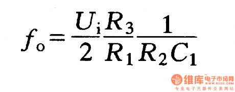
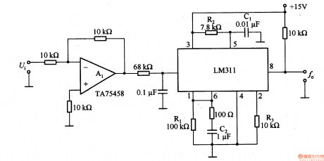
LM311 is the integrated chip within reference voltage, comparator circuit, amplifier, discharge circuit, and it is easy to use. In the circuit, the output frequency f0 is
(View)
View full Circuit Diagram | Comments | Reading(7066)
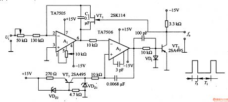
Voltage / frequency conversion circuit composed of two op amps
Published:2011/7/7 5:33:00 Author:Lucas | Keyword: Voltage conversion , frequency conversion , two , op amp
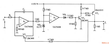
Among them, the operational amplifier Al is integral circuit, and operational amplifier A2 is the comparator circuit; transistor VTl for the discharge circuit. In the circuit, VT1 and VT2 use 2SC495, and VT3 uses 2SAlO15, operational amplifiers Al and A2 use TA75458. Output frequency fo ≈ Ui / (RlClU2), where, U2 is the regulator VDz is regulated voltage.
(View)
View full Circuit Diagram | Comments | Reading(753)
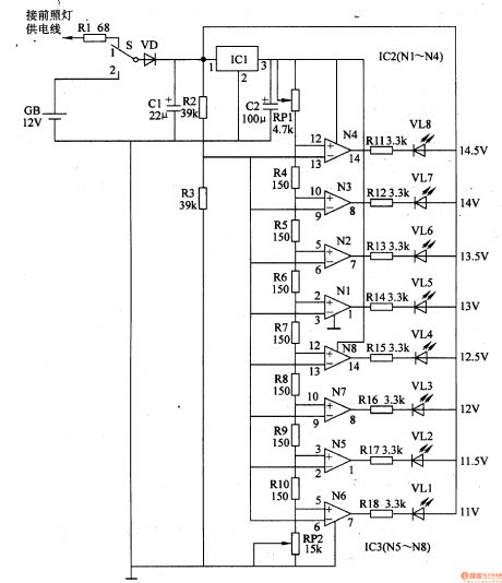
Motorcycle Speed Indicator (1)
Published:2011/7/9 5:41:00 Author:Sue | Keyword: Motorcycle, Speed Indicator
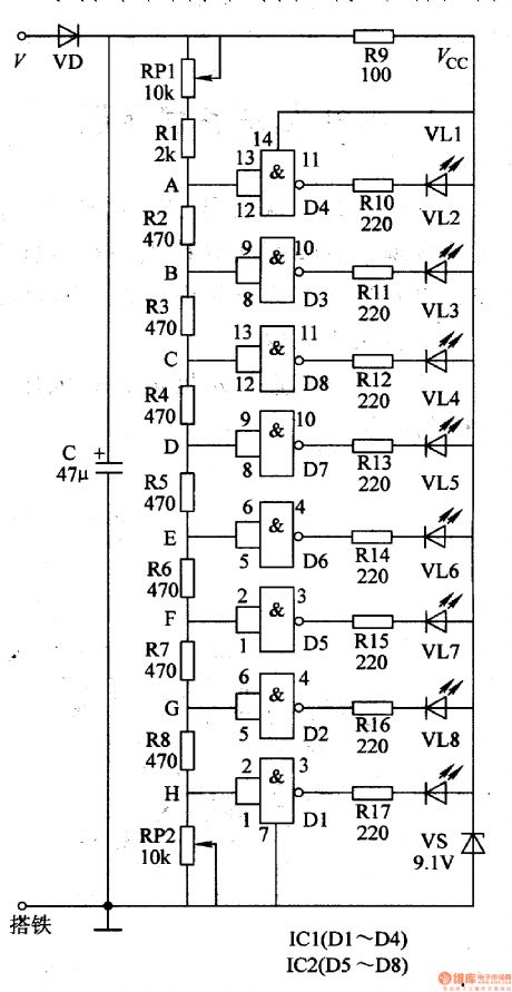
The alternator's output voltage V(It is achieved from ac voltage output from the alternator's head lamp's supply winding) will be divided into two circuits after it is rectificated by VD, filtrated by C. One circuit will provide IC2,IC1 and VL1-VL8 with 9v voltage after it is limited by R9, stablized by VS. The other circuit will generate 8 different detect voltage on A-H terminals after it is voltage divided by the voltage division circuit. When one terminal's detect voltage reaches NOT GATE circuit's threshold level, the NOT GATE circuit will output low level, which will make its output terminals outside circuit's diodes illuminated. The motorcycle rider can get to know the current motorcycle speed by the number and standard of illuminated diodes. (View)
View full Circuit Diagram | Comments | Reading(622)
Sewage Gas Leakage Alertor
Published:2011/7/10 7:29:00 Author:Sue | Keyword: Sewage Gas, Leakage, Alertor
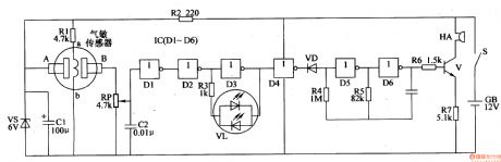
When there is combustible gas such as sewage gas, the gas sensor's electrode A and B will have a high resistance value. NOT GATE D1's and D3's input terminals both have low level and output terminals both have high level. VL will have green light. NOT GATE D4 outputs low level. VD is connected. The audio oscillator which consists of NOT GATE D5,D6 and R4,R5,C3 will not oscillate. HA makes no sound.
Whenthe gas sensor detectsa certain amount of sewage gas, the conducting inner resistor between A and B will become smaller which will make NOT GATE D1's and D3's input terminals have high level, and the output terminals have low level. VL will have red light. At the same time, NOT GATE D4 will output high level which will make VD disconnected. The audio oscillator will stop oscillating and will generate audio signal which will drive HA to make an alarm sound after the signal is amplified by V. (View)
View full Circuit Diagram | Comments | Reading(527)
Bean Sprouting Machine Constant Temperature Controller
Published:2011/7/10 7:27:00 Author:Sue | Keyword: Bean Sprouting Machine, Constant Temperature, Controller
When the power is on, the temperature of the bean sprouting machine is lower than RP3's given control temperature. RT's resistance value is large and IC's pin 2's and pin 6's voltages are both lower than pin 5's voltage. Pin 3 outputs high level and VT is connected. Heating wire EH begins to be heated. As the temperature is becoming higher and higher, RT's resistance value is becoming smaller and smaller. When the temperature reaches the given temperature, IC's pin 2's voltage is higher thanhalf of pin 5's voltage. When its pin 6's voltage is higher than or equal to pin 5's voltage, IC's inner circuit will be reversed. Its pin 3 outputs low level and VT is disconnected and EL stops being heated. As the temperature is becoming lower and lower, RT's resistance value is becoming higherand higher which will make IC's pin 2 and pin 6 have lower voltages. When IC's pin 6's voltage is lower than pin 5's voltage, its pin 2's voltage is lower than or equal to half of pin 5's voltage, IC's pin 3 will have high level again which will make VT connected. EH begins to be heated again. (View)
View full Circuit Diagram | Comments | Reading(1213)
Voltage / frequency conversion circuit composed of M51207
Published:2011/7/7 22:03:00 Author:Lucas | Keyword: Voltage conversion , frequency conversion
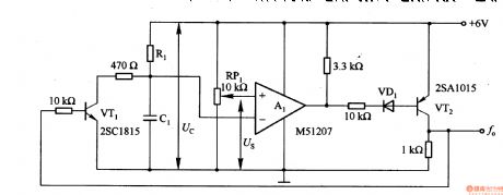
The circuit setting voltage Us has a wide range, and environmental temperature has no effect on it. Voltage / frequency conversion method is used as analog circuit and digital circuit.
(View)
View full Circuit Diagram | Comments | Reading(632)
Voltage / frequency conversion circuit composed of μA741
Published:2011/7/7 21:52:00 Author:Lucas | Keyword: Voltage conversion , frequency conversion
In the circuit, the AI and Rl, R2, Cl, etc. constitute a Miller integrator. Al's triangle wave output can drive level for the comparator. As the clamping effect of VD2, A2 outputs high level in about 0.7 V, low level in about -6V. A2's noninverting input added the feedback voltage is about half of the output voltage, so the upper trip point is about +0.3V, the lower trip point is about -3V. Al outputs triangle wave which is back and forth between +03 to -3V. When A2 outputs low level, VT1 gate voltage is negative and cut-off, R1 + R2 and C1 integrate on 2/3Ui.
(View)
View full Circuit Diagram | Comments | Reading(875)
Electronic Fish And Shrimp Catcher (2)
Published:2011/7/10 7:41:00 Author:Sue | Keyword: Electronic, Catcher
After the power switch is on, the 12v direct current voltage will provide V1 with start pulse through RP1,C3,VD3,T1 which will make V1 connected. Then under the back donation of R1,T1,T2 primary winding(W4,W5 winding), V1,V2 will go into push-pull oscillate states of intermittent connection and disconnection. T2's secondary winding(W6 winding) will generate 220v ac voltage which will become 400v direct current voltage after it is multivoltage rectificated by VD1,VD2,C1,C2, and the voltage will be put on the electrode A and B through relay K's normally open contact.
At the same time, after the astable oscillator begins to work, IC's pin 3 will output control voltage with an adjustable duty ratio which will make K work intermittently. Then between the electrode A and B there will be a continuous direct current high voltage. (View)
View full Circuit Diagram | Comments | Reading(2416)
μPC317H series of regulator, main features and pin of DC-DC circuit and power monitor
Published:2011/7/9 8:02:00 Author:Lucas | Keyword: regulator, main features, pin , DC-DC circuit , power monitor
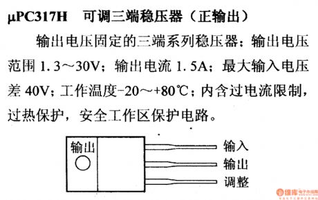
μPC317H adjustable regulator(positive output)
It is the three-terminal regulator with fixed output voltage; output voltage range is 1.3 ~ 30V; output current is 1.5mA; the maximum difference of input voltage is 40V; operating temperature is -20 ~ +80 ℃; it includes over-current limit, thermal protection, protection circuit in safe working area.
(View)
View full Circuit Diagram | Comments | Reading(811)
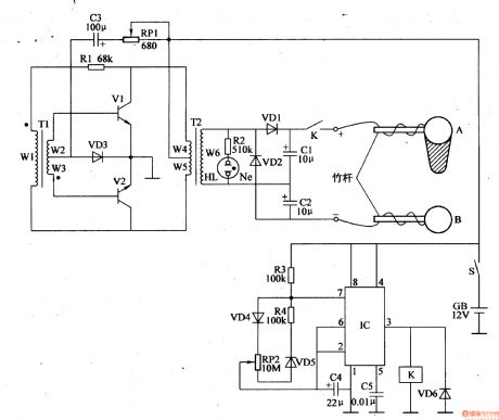
Electronic Fish And Shrimp Catcher (1)
Published:2011/7/9 6:56:00 Author:Sue | Keyword: Electronic, Fish Catcher
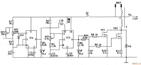
The dual time base integrated circuit IC's inner time base circuit and resistor R1,R2, capacitor C1,C2, LED VL1, potentiometer RP1,RP2 compose low frequency multivibrator. When the oscillator begins to work, VL1 will be illuminated.
IC's inner time base circuit, resistor R3,R4,LED VL2, potentiometer RP3, capacitor C3,C4 compose high frequency multivibrator. When the oscillator begins to work, VL2 will be illuminated.
The high voltage generator circuit consists of VMOS field effect transistor VF1,VF2, resistor R7-R11, zener diode VS and step-up transformer T.
Under the control oflow frequency multivibrator, the high frequency multivibrator will output pulse signal from IC's pin 9 which will generate pulse high voltage through the step-up transformer after the signal is amplified by VF1,VF2. (View)
View full Circuit Diagram | Comments | Reading(2306)
μPC2600H series of regulator, main features and pin of DC-DC circuit and power monitor
Published:2011/7/9 8:16:00 Author:Lucas | Keyword: regulator, main features, pin , DC-DC circuit , power monitor
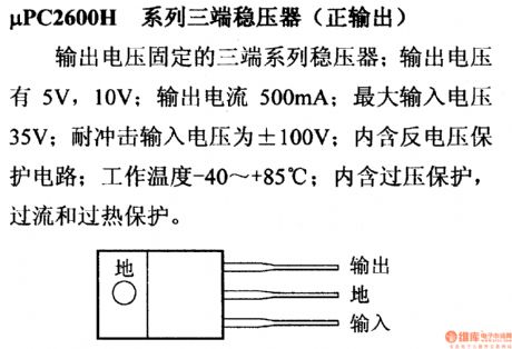
μPC2600H series of regulator ( with positive output)
It is the three-terminal regulator with fixed output voltage; output voltage is 5V, 10V; output current is 500mA; maximum input voltage is 35V; impact resistance input voltage is ± 100V; it contains anti-voltage protection circuit; operating temperature is -40 ~ +85 ℃ ; it includes overvoltage, overcurrent and overtemperature protection.
(View)
View full Circuit Diagram | Comments | Reading(443)
| Pages:1575/2234 At 2015611562156315641565156615671568156915701571157215731574157515761577157815791580Under 20 |
Circuit Categories
power supply circuit
Amplifier Circuit
Basic Circuit
LED and Light Circuit
Sensor Circuit
Signal Processing
Electrical Equipment Circuit
Control Circuit
Remote Control Circuit
A/D-D/A Converter Circuit
Audio Circuit
Measuring and Test Circuit
Communication Circuit
Computer-Related Circuit
555 Circuit
Automotive Circuit
Repairing Circuit