
Control Circuit
Index 86
Musical Lantern Controller(NE555,CD4066,CD4017)
Published:2011/8/18 5:50:00 Author: | Keyword: Musical Lantern, Controller
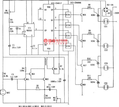
The picture shows the musical lantern control circuit. The controller consists of acoustic electric transduce and amplifying circuit, clock pulse generator, counting circuit and control circuit. The pickup transmitter MIC willconvert the acoustic signal to electric signal which will be put onto four circuits of analog switch CD4066(IC3) after it is amplified by BG1-BG3.
The clock pulse generator consists of IC1(555), W1,R1,R2,D1 and C1. The circuit's signalperiod T=0.693(Rw1+R1+R2)C1, and the correspondence period T in the picture varies in the range of 0.5-5s, among which 555(pin 3) is output and put on IC2 to work as CP pulse. (View)
View full Circuit Diagram | Comments | Reading(1404)
Industrial Touch Electronic Switch Circuit Composed of NE555,CD4013
Published:2011/8/10 7:21:00 Author:Sue | Keyword: Industrial, Touch, Electronic Switch
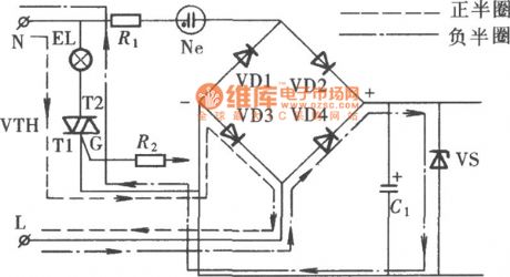
Industrial control switch is used frequently and has a complexed working environment. And it may be influenced by various interferences, so it is required to be strong and durable with easy operation and strong anti-interference ability. The circuit generates and forms trigger signal through touch signal input circuit. It triggers the bi-directional thyristor which will make the controlled circuit connected or disconnected. It has no reliable anti-interference circuit and its work is reliable. The picture shows the circuit. The circuit uses monostable trigger which is composed of NE555 to generate control pulse, and it uses bistable trigger which is composed of CD4013 as trigger control, and it uses bi-directional thyristor as control switch. (View)
View full Circuit Diagram | Comments | Reading(1441)
Mazda 96PROBE(2.5L) cruise control circuit
Published:2011/8/23 22:21:00 Author: | Keyword: Mazda, cruise control, 2.5L

The Mazda 96PROBE(2.5L) cruise control circuit is as shown in the figure:
(View)
View full Circuit Diagram | Comments | Reading(906)
Mazda 96PROBE body computer circuit
Published:2011/8/23 22:23:00 Author: | Keyword: Mazda, body computer
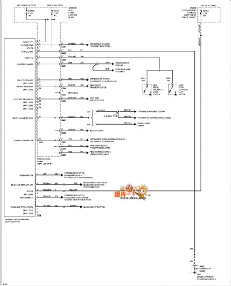
The Mazda 96PROBE body computer circuit is as shown in the figure:
(View)
View full Circuit Diagram | Comments | Reading(600)
Controllable conversion rate circuit
Published:2011/8/14 21:31:00 Author:TaoXi | Keyword: Controllable, conversion rate
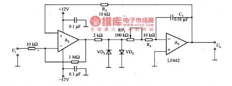
The controllable conversion rate circuit is as shown in the figure. It controls the conversion rate by adjusting the signal rising velocity, if it is used in the system which use the voltage signal to control the motor speed, it can control the deceleration and acceleration of the motor. The comparator circuit is composed of A1, the amplitude limiting circuit is composed of the VD1 and VD2. The conversion rate is decided by the VD1 and VD2's positive voltage drops and the product of the (R(RP1)+R1) and Cl, the larger the values of R(RP1), R1 and Cl, the smaller the conversion rate is.
(View)
View full Circuit Diagram | Comments | Reading(680)
The circuit uses the pulse width modulation mode to control the load
Published:2011/8/14 22:09:00 Author:TaoXi | Keyword: pulse width, modulation mode, load
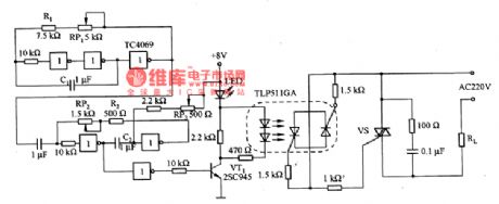
The circuit that uses the pulse width modulation mode to control the load is as shown in the figure. The oscillation frequency of the circuit is decided by the Rl+R(RP1) and C1, f=1/[2·2(Rl+R(RP1)Cl]. The waveform duty cycle is decided by the (Rz+R(RP2)) and C2. The optocoupler TLP5llGA has the electrical isolation effect for the output and input, so the output can use the 220V AC high voltage power supply. The LED can be used to display the changes of the duty cycle.
(View)
View full Circuit Diagram | Comments | Reading(949)
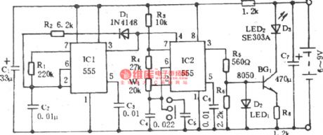
Electric fan infrared remote control governor circuit
Published:2011/8/11 20:00:00 Author:TaoXi | Keyword: Electric fan, infrared, remote control, governor
The electric fan infrared remote control governor circuit is as shown in the figure. (View)
View full Circuit Diagram | Comments | Reading(1250)
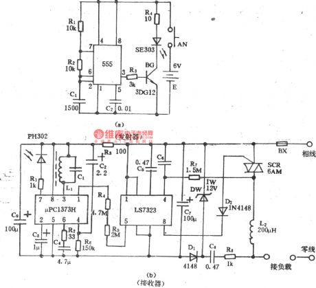
Electric fan infrared remote control speed control switch circuit
Published:2011/8/11 20:08:00 Author:TaoXi | Keyword: Electric fan, infrared, remote control, speed control switch
Emitter:
Receiver:
(View)
View full Circuit Diagram | Comments | Reading(974)
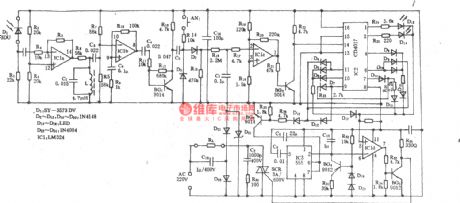
Incubator constant temperature control circuit
Published:2011/8/14 19:20:00 Author:TaoXi | Keyword: Incubator, constant temperature, control circuit
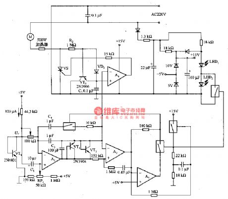
The incubator constant temperature control circuit is as shown in the figure. In this circuit, the control voltage has the linear relationship with the effective value of the heater converter, in the positive half cycle of the control thyristor vs cathode voltage, the AC22V voltage charges the timing capacitor C3 through the VD1 and R2. A4 is the comparator, it compares the voltage of C3 with the heater control voltage of C2, when the voltage of C3 is the same as the voltage of C2, A4 supplies the trigger pulse to the vs gate pole. This circuit uses the U2 to control the V2's pulse position, and it makes the C3 reset through VT5. The S shape U3 waveform makes the U2 have the good linear relationship with the effective value of the heater converter.
(View)
View full Circuit Diagram | Comments | Reading(2515)
Gain control circuit diagram
Published:2011/8/24 1:56:00 Author:Ecco | Keyword: Gain control
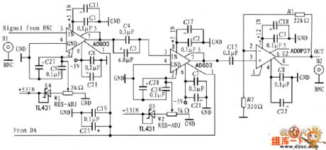
Gain control circuit consists of variable gain operational amplifier AD603 and precision op amp ADOP37. The AD603 is the core, and it is supplemented by external circuit programmable amplifier, and the gain control voltage is linear. SCM controls the D / A output amplifier gain. The circuit diagram is shown as the chart.
(View)
View full Circuit Diagram | Comments | Reading(2197)
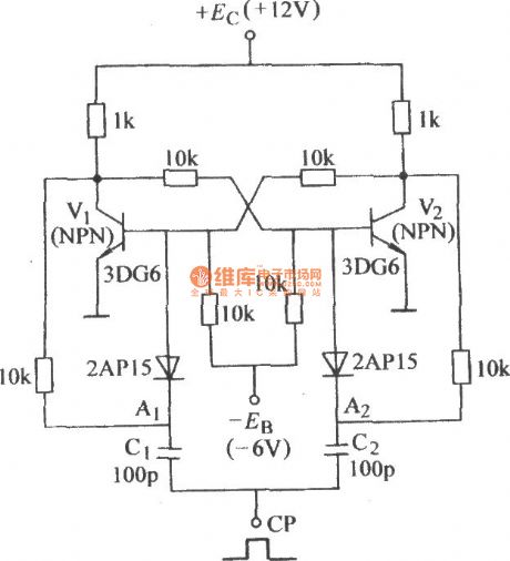
Bistable counting control trigger circuit
Published:2011/8/23 2:20:00 Author:Ecco | Keyword: Bistable counting, control trigger circuit
View full Circuit Diagram | Comments | Reading(760)
Disyllable control citcuit diagram
Published:2011/8/11 6:06:00 Author:nelly | Keyword: disyllable, control
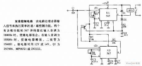
This cirucit executes simple on/off control function by amplifier inputing signal. when the input tone is 1800Hz, the relay is closed by two 567 decoders with self-locking function; when the input tone is 1950Hz, the relay releases. The diode is 1N4001. The relay can adopt 12V or 14V. Q1 is 2N3906, MPS6521 or 2N2222.
(View)
View full Circuit Diagram | Comments | Reading(793)
The base drive circuit of white light LED
Published:2011/8/11 5:24:00 Author:nelly | Keyword: drive circuit, white light LED
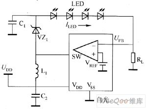
Composed of switch converter, the base drive circuit of white light LED is shown in the figure1, the general switch converter controls the converter's output voltage after the feedback voltage UFB and internal reference voltage UREF are compared. If the environmental brightness signal is introduced into the LED brightness control circuit, then the white light LED drive circuit which is shown in the figure1 is changed into the circuit in the figure 2. The difference between figure1 and 2 is: the circuit in the figure 2 has Tr1, resistance R1, R2 and OP amplifier IC1.
(View)
View full Circuit Diagram | Comments | Reading(735)
Voltage frequency transformation circuit diagram composed of AD654
Published:2011/8/10 6:34:00 Author:nelly | Keyword: voltage frequency, transformation

As shown in the figure, it is the low cost voltage frequency converter which is composed of AD654. Connecting the needed devices R1 and C1 as the figure, then it can be the VFC application circuit. The power voltage still can ensure the performance even drop to 4.5V, ensuring the performance to 16.5V, the maximum power consumption is 3mA(no load). The maximum frequency is 520KHz. The range of input voltage is 0~4V. The input measuring range Vi is decided by R1, Vi/R1=1mA. For example, Vi=0~1V, taking R1=1kΩ, Vi=0~5V, taking R1=5kΩ. The output frequency range is determined by C1, Fomax=1/10 C1, the frequency unit is KHz, C1's unit is μF.
(View)
View full Circuit Diagram | Comments | Reading(1582)
Practical pulse signal generator circuit diagram
Published:2011/8/10 3:53:00 Author:nelly | Keyword: pulse, signal generator
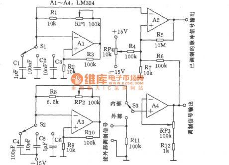
As shown in the figure, it is a practical pulse signal generator with adjustable duty cycle. The pulse frequency generator circuit is composed of A1 and some peripheral devices, it connects three different capacitors which have three different frequency measuring range, RP1 is used to accurately adjust the frequency. The modulation signal generator circuit consists of A3 and some peripheral devices, it also has three kinds of measuring range, RP2 is used to accurately adjust the frequency signal. RP3 is used to the gain adjust of modulation signal. RP4 controls the duty cycle.
(View)
View full Circuit Diagram | Comments | Reading(1025)
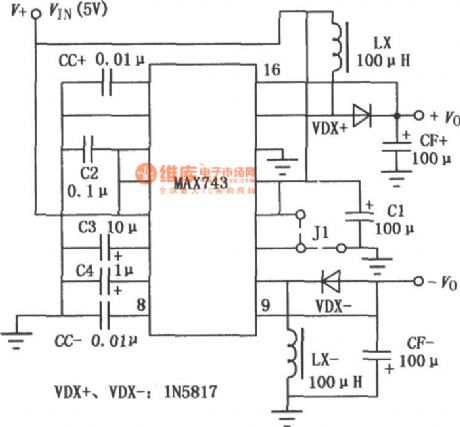
The classic applying circuit of MAX743 setting up switch DC-DC convertor
Published:2011/8/14 7:24:00 Author:leo | Keyword: Classic applying circuit, setting up switch, DC-DC convertor
View full Circuit Diagram | Comments | Reading(1036)
Photonics relay with locking function which is made by Darlington phototransistor
Published:2011/8/11 11:06:00 Author:leo | Keyword: Photonics relay, locking function, Darlington phototransistor
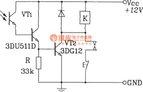
View full Circuit Diagram | Comments | Reading(733)
Key oscillator made by CC4528
Published:2011/8/14 7:00:00 Author:leo | Keyword: Key oscillator
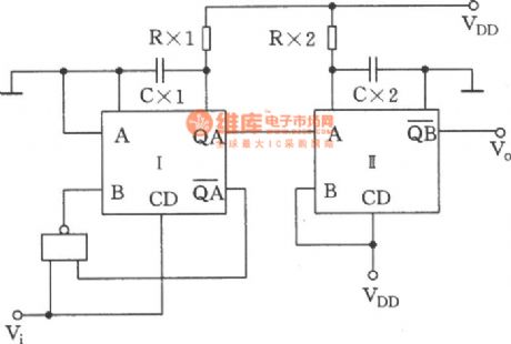
View full Circuit Diagram | Comments | Reading(633)
AC-DC three-digit voltmeter circuit
Published:2011/8/11 4:36:00 Author:John | Keyword: three-digit voltmeter
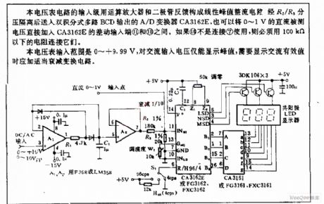
The voltmeter circuit’s input stage uses operational and a diode feedback to form a linear peak rectifier circuit. Then the circuit is isolated via R2/R3 divider and is sent to A / D converter CA3162E output from the dual integral multiple BCD. It can be also said to that the 0 ~ 1V DC test voltage is directly added between the differential inputs ⑾ and ⑽ of the CA3162E. If ⑽ is not connected to ⑺ for use, resistor with less than100kΩ should be used to connect to them. The voltmeter input ranges from 0 to +9.99 V. It only displays the peak value of the AC input voltage. When AC rms should be displayed, the transform circuit is needed to attenuate appropriately.
(View)
View full Circuit Diagram | Comments | Reading(2158)
LCD direct drive circuit
Published:2011/8/11 3:31:00 Author:John | Keyword: LCD, direct drive
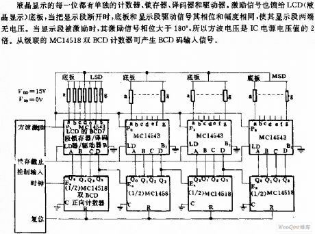
Every phase of LCD has the separate counter, latch, decoder and driver. Excitation signal is also fed back to the floor plate of LCD (liquid crystal display). When the display segment is disconnected, the floor plate and display segment drive signal to be with the same phase and amplitude. So there is no voltage across the segment. When the segment is encouraged, the excitation signal phase is greater than 180 °. So the square-wave voltage is two times more than the IC supply voltage. Dual-counter BCD from the cascade MC14518 can input signals by generating BCD code.
(View)
View full Circuit Diagram | Comments | Reading(1222)
| Pages:86/312 At 2081828384858687888990919293949596979899100Under 20 |
Circuit Categories
power supply circuit
Amplifier Circuit
Basic Circuit
LED and Light Circuit
Sensor Circuit
Signal Processing
Electrical Equipment Circuit
Control Circuit
Remote Control Circuit
A/D-D/A Converter Circuit
Audio Circuit
Measuring and Test Circuit
Communication Circuit
Computer-Related Circuit
555 Circuit
Automotive Circuit
Repairing Circuit