
Control Circuit
Index 91
The Circuit Diagram of 60Hz Notch Filter Consist of INA110
Published:2011/8/8 21:42:00 Author:Felicity | Keyword: Notch Filter, 60Hz
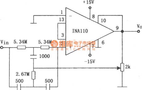
The figure shows the 60Hz notch filter consist of INA110 and double-T network. The 2kΩ potentiometer can adjust Q in this circuit. When the frequency of the city electricity is 50Hz, the resistance of this filter need to be changed, 5.34MΩ into 6.37MΩ and2.67MΩ into 3.16MΩ.This circuit can filter out the AC noise from the circuit. (View)
View full Circuit Diagram | Comments | Reading(1796)
The logic high and low LEV LED digital display circuit
Published:2011/8/3 23:23:00 Author:Seven | Keyword: logic, LEV, digital display
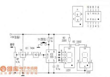
Here is to introduce the logic probe detector indicated by LED, the circuit is simple and direct, and it needs no debugging while manufacturing, the circuit is shown in figure 1. The circuit structure and working principle is shown in figure 1, IC 1(N1 and N2) is 6 phase reversers 7404, there are only 2. IC2 and relevant elements compose the dual steady circuit. The switch S1 composes the 555 dual steady reset circuit. LED1 and LED2 are 2 common positive digit tube.
(View)
View full Circuit Diagram | Comments | Reading(824)
The circuit diagram of frequency-adjustable band-pass filter (μA748)
Published:2011/8/9 2:40:00 Author:Felicity | Keyword: band-pass filter, frequency-adjustable
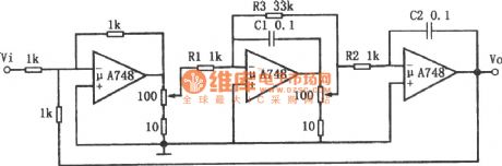
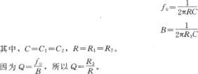
The resonant frequency of this filter can be adjusted by in-line potentiometer and Q can remain basically unchanged. Changing the position of the potentiometer is the same as adding a voltage divider. It can reduce the current that in R1, R2 and R3 which can be seen as increasing the resistance of R1, R2 and R3.As the potentiometer changed, the bandwidth and resonant frequency are also changed while Q remains basically unchanged. It’s because that the change of R1, R2, and R3 are the same. Changing the capacity of capacitor C1 can change the work frequency of the filter, but the adjustable extent of the bandwidth is not large. (View)
View full Circuit Diagram | Comments | Reading(1035)
ultrasonic insect repellent circuit with CD4017
Published:2011/7/20 23:06:00 Author:chopper | Keyword: ultrasonic, insect repellent
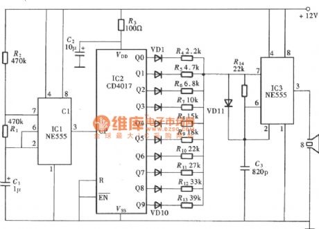
View full Circuit Diagram | Comments | Reading(5481)
quadruplex interlock switch(2) (CD4028、CD40107)circuit
Published:2011/7/20 23:12:00 Author:chopper | Keyword: quadruplex, interlock switch, secondary circuit
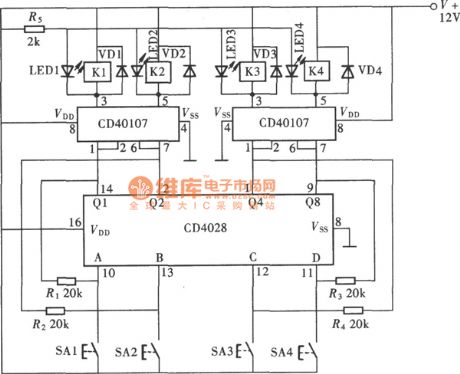
View full Circuit Diagram | Comments | Reading(3173)
stair light control switch circuit with CD4028
Published:2011/7/20 23:32:00 Author:chopper | Keyword: stair light, control switch
View full Circuit Diagram | Comments | Reading(2928)
responder (CD4011) circuit with nand gate
Published:2011/7/20 23:43:00 Author:chopper | Keyword: responder circuit, nand gate

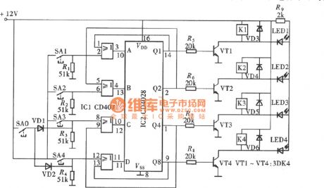
Quiz responder is a very typical interlock circuit.As long as one of participates first presses the responder,the others are invalid.The responder shown in the picture can be used for many people to attended the answer,in the circuit there are only two groups.And it can add some groups according to the actual need in the practical usage.And the circuit is shown as picture.Each group of the responders is formed by a answer button, an input control gate, a RS trigger and a luminescent indicator circuit.
(View)
View full Circuit Diagram | Comments | Reading(1668)
LED sign decorative light(4)
Published:2011/7/25 2:13:00 Author:chopper | Keyword: LED sign, decorative light
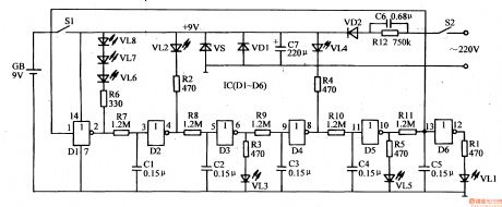
This example describes the LED sign decorative light,which can be made into the electronic road sign in theater,dance hall and other public places, as the safe passage in the bathroom. The principle of circuit The LED sign decorative light circuit is formed by the LEDs VL1-VL8, six non-gate integrated circuit IC (D1-D6), resistors B1-R12 and capacitors C1-C5, which is shown in Figure 1-156
The circuit adopts 9V laminated battery,and can also use the regulated power supply formed by capacitor C6, C7, resistor R12, rectifier diodes VD1, VD2 and a voltage-regulator diode VS
(View)
View full Circuit Diagram | Comments | Reading(2007)
LED sign decorative light(3)
Published:2011/7/20 0:13:00 Author:chopper | Keyword: LED sign, decorative light
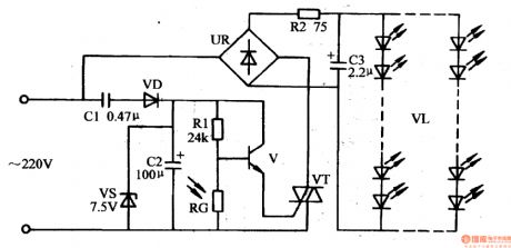
This example describes light-controlled LED sign decorative light which adopts divided components.And it does not work during the day, and automatically lights up at night, which is of traits like low power consumption, long life, maintenance-free, easy to make and so on. The principle of circuitThe LED sign decorative light circuit is formed by the power supply circuit, light-controlled circuit and LED display circuit,which is shown in Figure 1-155. The power supply circuit is formed by the capacitor C1, rectifier diode VD, voltage regulator diode VS and filter capacitor C2.
(View)
View full Circuit Diagram | Comments | Reading(2162)
LED sign decorative light(2)
Published:2011/7/20 0:44:00 Author:chopper | Keyword: LED sign, decorative light
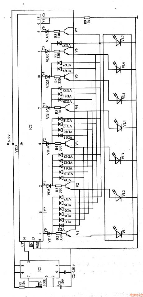
This example describes the LED sign decorative light,which uses some LEDs to form some words(for example, Please don't spit ). When the power is available, the seven characters light up one by one,finally they form Please do not spit , and then seven characters all turn off,then repeat the next cycle. The principle of circuit The LED sign decorative light circuit is formed by the clock generator, count distributor and LED display drive circuit, which is shown in Figure 1-154
(View)
View full Circuit Diagram | Comments | Reading(1023)
LED sign decorative light(1)
Published:2011/7/20 4:45:00 Author:chopper | Keyword: LED sign, decorative light
This example describes the LED sign decorative light,which is used to decorate all kinds of doors mark,road sign and emergency exit,fire access and other signs, and it can produce effects like text flashing,border flowing,and it will play a role of eye-catching, decorative effects. The principle of circuitThe LED sign decorative light circuit is formed by the power supply circuit,light flowing control circuit and text flashing control circuit, which is shown in Figure 1-153. Power supply circuit is formed by the rectifiers diodes VD1-VD5, resistor R1, voltage regulator diode VS and filter capacitor C1, C4.
(View)
View full Circuit Diagram | Comments | Reading(1741)
irrigation motor automatic protector (2)
Published:2011/7/20 4:51:00 Author:chopper | Keyword: irrigation motor, automatic protector
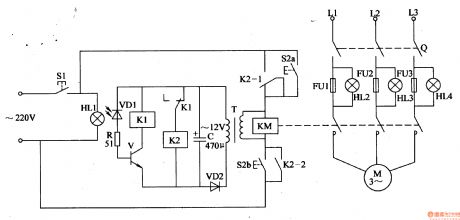
Rural irrigative pump motor often be burned due to low voltage or phase lack when it runs.This example describes the irrigation motor automatic protector, which can cut off three-phase AC power supply to protect the motor when the phase is lack. The principle of circuitThe irrigation motor automatic protection circuit is formed by the start control circuit, phase-lack control circuit and test circuit,which is shown in Figure 4-97. Start circuit is formed by the start button S2 (S2a, S2b), AC contactor KM and relay K2,etc.
(View)
View full Circuit Diagram | Comments | Reading(1075)
farmland irrigation and drainage line anti-theft alarm(2)
Published:2011/7/20 5:14:00 Author:chopper | Keyword: farmland, irrigation and drainage line, anti-theft alarm
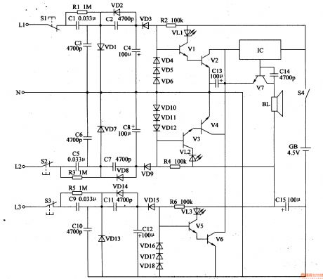
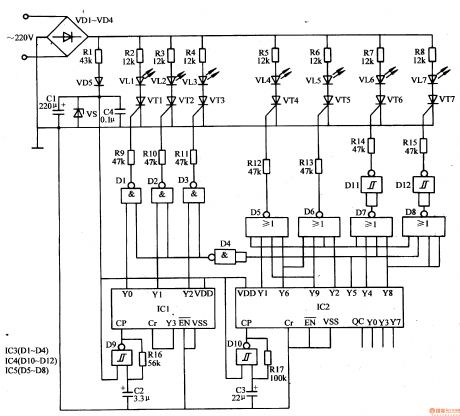
This example describes the farmland irrigation and drainage line anti-theft alarm, which controls the anti-theft alarm by detecting whether there is AC voltage of the each phase of the three-phase AC current or not.When the power line of farmland irrigation and drainage is stolen or the power outages,and phase lack of power line leads to a phase withoutAC voltage, the alarm will send an alarm signal in time. The principle of circuitThe farmland irrigation and drainage line anti-theft alarm is formed by the detection circuit,LED indication circuit and audible alarm circuit, which is shown in Figure 4-9. Detection circuit is formed by the test buttons S1-S3, resistors R1-R3, capacitors C1-Cl2 and diodes VD1-VD3, VD7, VD9, VD13-VD15.
(View)
View full Circuit Diagram | Comments | Reading(1067)
farmland irrigation and drainage line anti-theft alarm(1)
Published:2011/7/20 5:01:00 Author:chopper | Keyword: farmland, irrigation and drainage line, anti-theft alarm
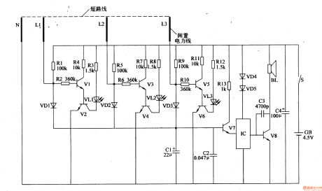
This example describes the farmland irrigation and drainage line anti-theft alarm.It can send out the alarm in time and point out the relevant line which is cut off when the power lineis in the destruction, which played a role in anti-theft protection. The principle of circuitThe farmland irrigation and drainage line anti-theft alarm circuit is formed by the detection circuit and sound alarm circuit, which is shown in Figure 4-93. Detection circuit is formed by the resistors R1-R12, LEDs VL1-VL3, transistors V1-V6.
(View)
View full Circuit Diagram | Comments | Reading(672)
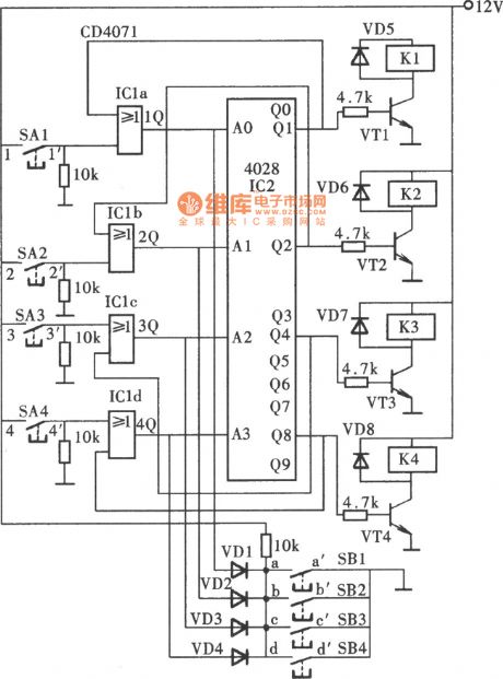
quadruplex interlock switch circuit(1)(CD4028)circuit
Published:2011/7/20 23:11:00 Author:chopper | Keyword: quadruplex, interlock switch
View full Circuit Diagram | Comments | Reading(4755)
The Circuit Diagram of 1 MHz High-pass Filter Consists of OPA603
Published:2011/8/8 7:54:00 Author:Felicity | Keyword: High-pass Filter
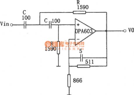
The figure shows the 1 MHz high-pass filter circuit. This circuit uses high speed current feedback operational amplifier OPA603 with 100MHz bandwidth and 1000V/μs slew rate. It is a second order Butterworth high-pass filter and the corner frequency f0=1/2πRC. Adopting the parameters shown in the figure, f0=1MHz and the circuit gain is 1.6. (View)
View full Circuit Diagram | Comments | Reading(1152)
The circuit diagram of notch filter consists of MC33171
Published:2011/8/8 6:51:00 Author:Felicity | Keyword: notch filter
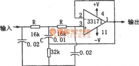
The figure shows the notch filter circuit. This circuit uses high-performance amplifier MC33171 to build up notch filter. This component has wide bandwidth and high switching rate. The notch frequency can be changed by adjusting the value of R and C: f=1/4πRC. (View)
View full Circuit Diagram | Comments | Reading(970)
The circuit diagram of multiplication circuit 2 (MPY100)
Published:2011/8/6 0:14:00 Author:Felicity | Keyword: multiplication circuit
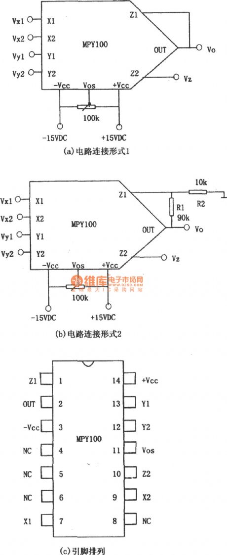
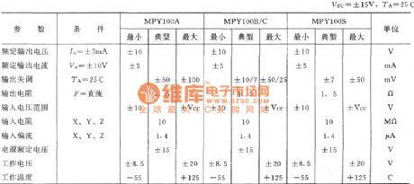
The increase of the factor of proportionality causes the Offset Voltage to rise, and this need zero modulation. Besides it can narrow the bandwidth. The figure shows the circuit diagram of multiplication circuit 2 (MPY100). Main parameters of MPY100: (View)
View full Circuit Diagram | Comments | Reading(816)
The Circuit Diagram of Active High-pass Filter (LM102)
Published:2011/8/8 11:29:00 Author:Felicity | Keyword: Active High-pass Filter

The figure shows the circuit diagram of active low-pass filter. The cutoff frequency fc=100Hz. In the circuit, the ratio of R1 to R2 or of C1 to C2 can be any value. In this circuit, R1=R2 and C1=2C2. C1=C2 and R1=2R2 can also be okay.
(View)
View full Circuit Diagram | Comments | Reading(2389)
Agricultural Irrigation Controller (the 2nd)
Published:2011/8/6 21:06:00 Author:Felicity | Keyword: Agricultural Irrigation, Controller
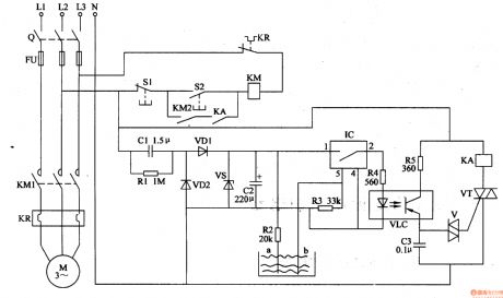
Work of the circuit
The circuit consists of power circuit, level detection control circuit and control implication circuit. (It is showed in picture 4-92.)
Power circuit consists of Buck capacitor Cl, discharge resistors Rl, rectifier diodes VDl, VD2, voltage regulator diode VS and filter capacitor C2.
Level detection control circuit consists of level detection electrodes a, b, resistors R2-R4, electronic integrated switching circuits and optical fused devices VLC.
Control implication circuit consists of Light garnet together control VLC, capacitor C3, resistor R5, bi-directional trigger diode V, VT and relay thyristor KA.
(View)
View full Circuit Diagram | Comments | Reading(690)
| Pages:91/312 At 2081828384858687888990919293949596979899100Under 20 |
Circuit Categories
power supply circuit
Amplifier Circuit
Basic Circuit
LED and Light Circuit
Sensor Circuit
Signal Processing
Electrical Equipment Circuit
Control Circuit
Remote Control Circuit
A/D-D/A Converter Circuit
Audio Circuit
Measuring and Test Circuit
Communication Circuit
Computer-Related Circuit
555 Circuit
Automotive Circuit
Repairing Circuit