
Control Circuit
Index 96
TEMPERATURE_COMPENSATED_CONSTANT_CURRENT_GENERATOR
Published:2009/7/14 5:26:00 Author:May


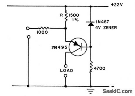
Reverse voltage characterisitic of zener, in conjunction with baseemitter characteristic of transistor, stabilizes collector current by maintaining constant voltage across R from-55 to+25℃.-Temperature-Compensated constant Current Generator. Electronic Circuit Design Handbook, Mactier Pub.Corp.N.Y.1965,P169. (View)
View full Circuit Diagram | Comments | Reading(811)
TRANSISIOR_OVERLOAD_PROTECTION
Published:2009/7/14 5:24:00 Author:May
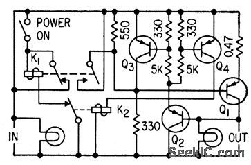
Current greater than 3 amp flowing through 0.47-ohm resistor in emitter of current-switching transistor Q1 drops voltage on base of Q2, causing Q2, Q3, and Q4 to saturate. Q3 opens circuit immediately and keeps it open for duration of overload, For complete short-circuits, Q4 latches K2 to provide positive protection.-F. W. Kear, Fast-Response Over-loud Protection, Electronics, 33:7, p125. (View)
View full Circuit Diagram | Comments | Reading(771)
50000_AMP_SINGLE_PULSE_CURRENT_SWITCH_
Published:2009/7/14 5:21:00 Author:May
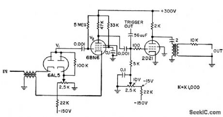
Simple triggered-gap switch operates at voltage down to 1kv to control switching with time jitter of only 0.1 microsec between successive pulses. Can be used for magnetron testing, surge-current generator, and flash-lamp source. Output of trigger generator is clomped sine wave having sufficient amplitude to break down gap in switch and initiate current pulse. V1 and V2 serve as sharpener for triggering pulse.-E. H. Cullington, W. G. Chace, and R.L. Morgan. Low-Voltage Trigger Controls High Currents, Electronics, 31:15, p 86-88. (View)
View full Circuit Diagram | Comments | Reading(1164)
THEREMIN_VOLUME_CONTROL_CIRCUIT
Published:2009/7/14 4:58:00 Author:May
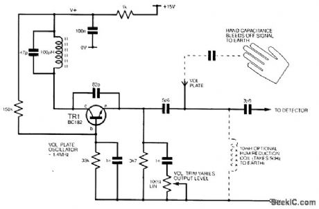
The circuit shows a capacitive potential divider with volume trim on the fixed oscillator. The hand capacitance loads down the RF to a detector stage, reducing the detector output. This output is used to control the gain of an audio amplifier. (View)
View full Circuit Diagram | Comments | Reading(2083)
HALL_MULTIPLIER_FIELD_COIL_DRIVE
Published:2009/7/15 3:15:00 Author:Jessie
Feedback amplifier drives field coil current in phase with input signal over range of 0 cps to 7 kc, with less than 1.5% distortion. –R. A. Greiner, Feedback Amplification Improves Hall-Effect Multipliers, Electronics, 34:34, p 52-55. (View)
View full Circuit Diagram | Comments | Reading(868)
0_10_kHz_WITH_0_10_V_CONTROL
Published:2009/7/14 4:58:00 Author:May
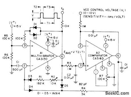
CA3130 MVBR generates pulses of constant amplitude V and width T2. Average output voltage is applied to noninverting input of comparator (through integrating network R3-C2. Comparator output signal from pin 6 is fed through R4 and D4 to inverting terminal 2 of A1 for adjusting MVBR interval T3 so EAVG is equal to control voltage.- Linear Integrated Circuits and M0Sf/FET's, RCA Solid State Division. Somerville, NJ, 1977, p 269.
(View)
View full Circuit Diagram | Comments | Reading(761)
_5_V_SWITCHING
Published:2009/7/14 4:54:00 Author:May
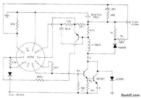
Unitrode U2T201 Darlington serves as switching element for LM304 step-down switching regulator operating from input of -25 V. Operating frequency can be about 25 kHz. Darlington will handle peak currents up to 10 A.- Designer's Guide to Power Darlingtons as Switching Devices, Unitrode, Watertown, MA, 1975, U-70, p 10. (View)
View full Circuit Diagram | Comments | Reading(945)
VACUUM_TUBE_THEREMIN_VOLUME_CONTROL_CIRCUIT
Published:2009/7/14 4:53:00 Author:May

Gain is controlled by a variable negative grid bias in an audio amplifier stage. This oscillator produces a negative dc voltage by means of a rectifier. As a hand is brought up to the volume plate antenna, this loads the oscillator, reducing output and hence the negative dc output. This means increased gain for the controlled audio stage. (View)
View full Circuit Diagram | Comments | Reading(1119)
HIGH_VOLTAG_E_POSITIVE_SWITCHING
Published:2009/7/14 5:02:00 Author:May
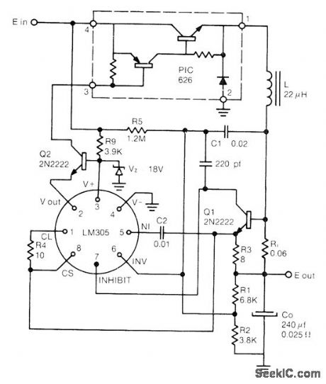
Designed for operation from supply voltages above 40-V maximum rating of LM305 regulator. Output is +5 V at up to l0 A. Circuit uses fraction of input voltage as determined by R9 and zener, with Q2 providing voltage isolation between regulator and Unitrode PIC626 hybrid power switch.- Switching Regulator Design Guide, Unitrode, Watertown, MA, 1974, U-68A, p 9. (View)
View full Circuit Diagram | Comments | Reading(842)
OSCILLATOR_CONTROL
Published:2009/7/14 5:02:00 Author:May
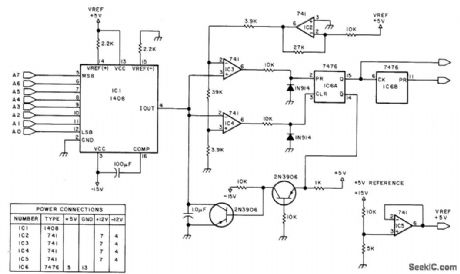
Digitally controlled oscillator generates frequency proportional to integer output to 1408 DAC, for use as clock input of speed and direction control for bidirectional logic stepper motor serving as one output of microprocessor. Used to provide speed control for stepper. Number of bits determines number of speed selections available under computer control.-R.E. Bober, Taking the First Step, BYTE, Feb. 1978,p 35-36,38,102,104,106.and 108-112.
(View)
View full Circuit Diagram | Comments | Reading(0)
50_V_AT_1_kW
Published:2009/7/14 5:01:00 Author:May
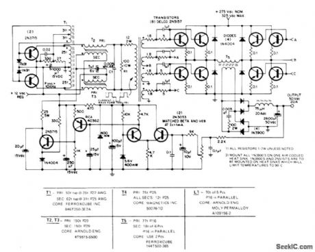
Switching regulator operating at 10 kHz uses pulse-width modulation to give 87% efficiency at full load. Input voltage is 275 VDC. Inverter output drives combination of eight Delco 2N5157 power transistors connected in paralleled pairs in each leg of bridge circuit. Clamp diodes in each bridge leg prevent reverse conduction through collector-base diodes of transistors. Regulator consists of differential amplifier and two-stage DG amplifier controlling direct current through windings of magnetic amplifier.- One Kilowatt Regulated Power Converter with the 2N5157 Silicon Power Transistor, Delco, Kokomo, IN, 1972, Application Note 44, p 3. (View)
View full Circuit Diagram | Comments | Reading(1011)
_5_V_SWITCHING_AT_10_A
Published:2009/7/14 4:47:00 Author:May
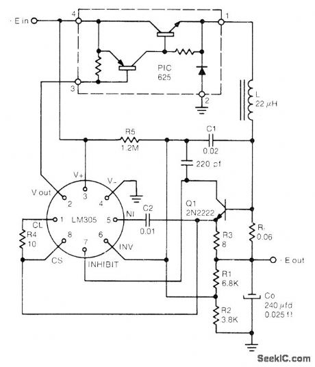
Unitrode PIC625 hybrid power switch provides switching action for LM305 regulator at switching speeds up to 100 kHz for input voltage range of 20-40 V. Circuit operates in fixed OFF-time mode that makes output ripple independent of input voltage. Q1 provides current-limiting action.- Switching Regulator Design Guide, Unitrode, Watertown, MA, 1974, U-68A, p 7. (View)
View full Circuit Diagram | Comments | Reading(2006)
15_V_FROM_75_30V
Published:2009/7/14 4:36:00 Author:May
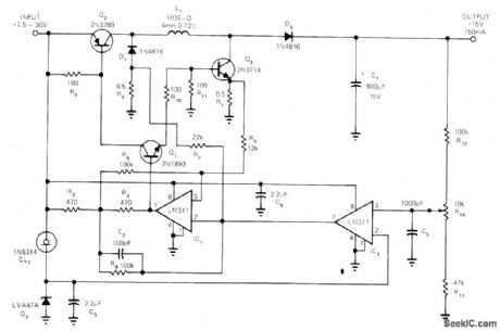
Switching regulator operation is independent of input voltage level. When power is applied, Q1 conducts and turns on Q2 and Q3 When linear rising current of Q1 exceeds upper threshold as sensed by R1, IC1 switches to low output state and turns off all three transistors. Voltage across L1 reverses, and current flows into C1 through D1 and D2. When this current as sensed by R2 falls below lower threshold, IC1 switches back to its high output state. This oscillating action continues until output voltage as sensed by IC2 rises above desired level, when IC2 switches to its low out-put state and holds IC1 low until output drops back below preset level to complete one cycle of oscillation.-A. Delagrange, Voltage Regulator Can Have Same Input and Output Level, EDN Magazine. Aug. 5, 1973, p 87 and 89. (View)
View full Circuit Diagram | Comments | Reading(808)
REMOTE_FINE_TUNING
Published:2009/7/14 4:36:00 Author:May
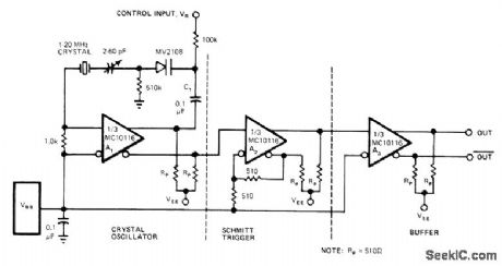
Addition of voltage-variable capacitance diode to crystal feedback path provides capacitance range of 50 to 12 pF with tuning voltage range of 0-30 V. Diode supplements 2-60 pF trimmer capacitor that adjusts oscillator frequency with respect to control-voltage input. Inverting input of A1 connects to reference voltage VBB, which is available on pin of MC10116 and is center volt-age of output signal swing of amplifier. A2 is connected as Schmitt trigger to give high-speed rise and fall times. Frequency deviation on either side of center is function of crystal frequency and ranges from±50 to±300 PPM for crystals between 1 and 20 MHz.-B. Blood, Fine-Tune This Oscillator with Voltage, EDN Magazine, Aug. 5, 1978, p 74. (View)
View full Circuit Diagram | Comments | Reading(1045)
THYRATRON_AFC_FOR_AIRBORNE_RADAR
Published:2009/7/15 3:38:00 Author:Jessie
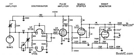
Uses Weiss discriminator, which for large bandwidths is easier to adjust than Foster-Seeley, and requires no special i-f transformer. Employs two thyratrons to generate required control voltage for repeller of klystron. -NBS, Handbook Preferred Circuits Navy Aeronautical Electronic Equipment, Vol. I, Electron Tube Circuits,1963, p N 13-4. (View)
View full Circuit Diagram | Comments | Reading(1173)
_5_V_TO__15_V
Published:2009/7/14 4:32:00 Author:May
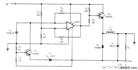
Use of switching regulator for voltage conversion permits generation of higher output voltage along with polarity reversal. LM311 operates as free-running MVBR with low duty cycle. Frequency is determined by C1 and R5 and duty cycle by divider R3-R4. Extra loop function performed by Q1 and zener operating in conjunction with resistor network modifies oscillator duty cycle until desired out-put level is obtained. Nominal frequency is 6 kHz, duty cycle is 20% for -15 V output, and maximum load current is 200 mA. Design equations are given.-H, Mortensen, IC Comparator Converts +5 to -15V DC, EDN Magazine, Dec. 20, 1973, p 78-79. (View)
View full Circuit Diagram | Comments | Reading(910)
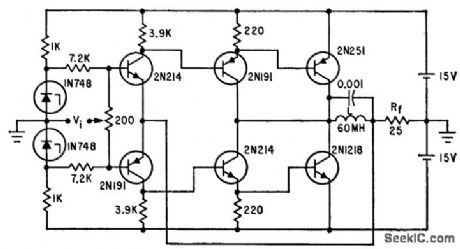
LASER_MODULATOR_CURRENT_CONTROL
Published:2009/7/14 4:31:00 Author:May
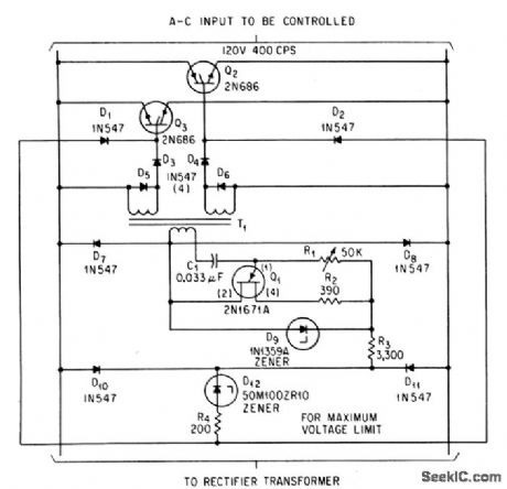
When modulator or pumping current for laser is lost, output voltage of pulse transformer T1 will rise to limit set by zener D12, which then conducts lo make Q2 and Q3 absorb current not required by energy storage capacitors.-S.J. Grabowski Pulse Power Supply Design for Laser Pumping Electronics,36:51,p33-35. (View)
View full Circuit Diagram | Comments | Reading(874)
24_V_D_C_TO_SQUARE_WAVE_A_C
Published:2009/7/15 3:33:00 Author:Jessie
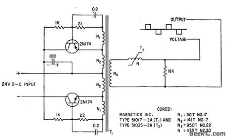
Will replace sine-wave source because square wave output is modified by series saturable reactor to have same rms and average values as pure sine wave.-D. Levy, Replacing Sine Wave Sources with Solid-Stale Inverters, Electronics, 34:26, p 80-83. (View)
View full Circuit Diagram | Comments | Reading(1177)
MICROWAVE_KLYSTRON_AFC
Published:2009/7/15 3:32:00 Author:Jessie
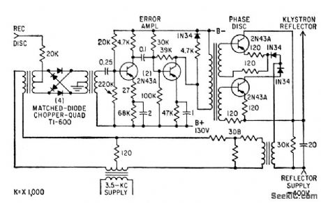
Uses signal from discriminator of 6,000-Mc microwave receiver to stabilize frequency of local-oscil-lator klystron. Balanced silicon-diode input chopper lattice is excited at 3.5 kc, but only error signal from discriminator will unbalance network and pass 3.5 kc on to error amplifier.-M. C. Harp, Nonvacuum Devices Control Klystrons, Electronics, 32;7, p 68-70. (View)
View full Circuit Diagram | Comments | Reading(1677)
HIGH_VOLTAGE_NEGATIVE_SWITCHING
Published:2009/7/14 4:18:00 Author:May
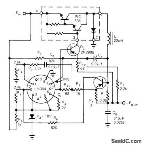
Uses zener to reduce supply voltage to acceptable level for LM304 IC regulator,Base drive and voltage isolation are provided by Q2, R10, and R11 for PIC636 hybrid power switch Circuit operates in fixed OFF-time mode, -L. Dixon and R. Patel, Designers' Guide to:Switching Regulators, EDN Magazine. Oct. 20, 1974, p 53-59. (View)
View full Circuit Diagram | Comments | Reading(789)
| Pages:96/312 At 2081828384858687888990919293949596979899100Under 20 |
Circuit Categories
power supply circuit
Amplifier Circuit
Basic Circuit
LED and Light Circuit
Sensor Circuit
Signal Processing
Electrical Equipment Circuit
Control Circuit
Remote Control Circuit
A/D-D/A Converter Circuit
Audio Circuit
Measuring and Test Circuit
Communication Circuit
Computer-Related Circuit
555 Circuit
Automotive Circuit
Repairing Circuit