
Control Circuit
Index 82
The upper limit and lower limit temperature control audio alarm circuit MAX6502/3
Published:2011/8/30 2:33:00 Author:Christina | Keyword: upper limit, lower limit, temperature control, audio, alarm circuit
View full Circuit Diagram | Comments | Reading(857)
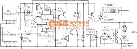
Excessive carbon monoxide automatic exhaust voice alarm circuit
Published:2011/8/30 2:46:00 Author:Christina | Keyword: Excessive carbon monoxide, automatic exhaust, voice, alarm circuit
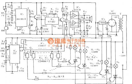
As the figure shows, it is composed of the gas sensor, the solid-state language circuit, the monostable timing circuit, the SCR trigger exhaust fan circuit, the AC step-down rectifier circuit. It can be used in the room which burns the coal, when the coal is not fully burned, the harmful gas such as the carbon monoxide will exceed the standard, the circuit will open the exhaust fan automatically, and it will send out the voice of The carbon monoxide exceeds the standard, please be careful of the gas poisoning to ensure the personal safety.
(View)
View full Circuit Diagram | Comments | Reading(1410)
Three-diode rectification energy consumption braking circuit
Published:2011/8/30 2:56:00 Author:Christina | Keyword: Three-diode, rectification, energy consumption, braking circuit
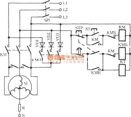
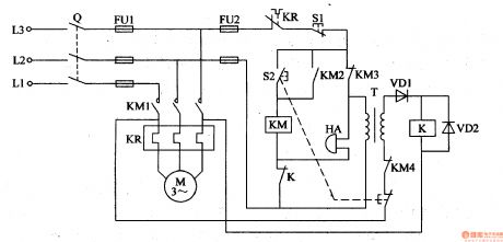
As the figure shows, when you press the STP, the AC contactor KM will loss the electrical energy and release, the KMB and KT get the electrical energy to act immediately, the two groups of main contactor of KMB will make the three-phase winding wire of the electromotor M get into the short circuit state, the other three groups of main contactor introduce the three-phase half wave rectifying power supply to make the stator winding of the electromotor M connect into the symmetrical parallel line, so we achieve the purpose of braking. Then the KT cuts off, the KMB losses the electrical energy to release, the braking is over. R is the limiting resistor.
(View)
View full Circuit Diagram | Comments | Reading(1145)
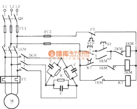
Three-capacitor|braking circuit
Published:2011/8/30 2:59:00 Author:Christina | Keyword: Three-capacitor braking circuit
View full Circuit Diagram | Comments | Reading(846)
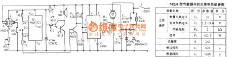
Three-phase exhaust fan electricity saving automatic control circuit
Published:2011/8/30 3:07:00 Author:Christina | Keyword: Three-phase, exhaust fan, electricity saving, automatic control
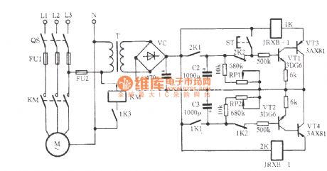
In some poorly ventilated place, the long-term operation of the exhaust fan will waste the electricity, and the exhaust fan is easy to burn out. The circuit of the figure can achieve the automatic stop of the exhaust fan M, also the automatic start of the exhaust fan M. The interval time is set by the potentiometers RP1 and RP2.
(View)
View full Circuit Diagram | Comments | Reading(2398)
Three electromotors sequence-start reversed order stop circuit
Published:2011/8/30 20:28:00 Author:Christina | Keyword: Three electromotors, sequence-start, reversed order, stop circuit
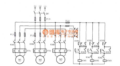
Some technological processes need the three electromotors, the sequence-start order is M1, M2, M3, the reversed order is M3, M2, M1. In this circuit, the normally open contact point of KM1 is connected into the control loop of KM2; the normally open contact point is connected into the control loop of KM3, if the KM1 will not close, the electromotor M1 is not the first start one, so the electromotor M2 can not start; also the M3, this is the sequence start. The reason of the reversed order stop is that the normally open auxiliary contact point of KM3 is connected with the two ends of the stop button STP2, the normally open auxiliary contact point of KM2 is connected with the two ends of the stop button STP1.
(View)
View full Circuit Diagram | Comments | Reading(3487)
Three coils voltage relay balance control broken phase protection circuit
Published:2011/8/30 20:47:00 Author:Christina | Keyword: Three coils, voltage relay, balance control, broken phase, protection circuit
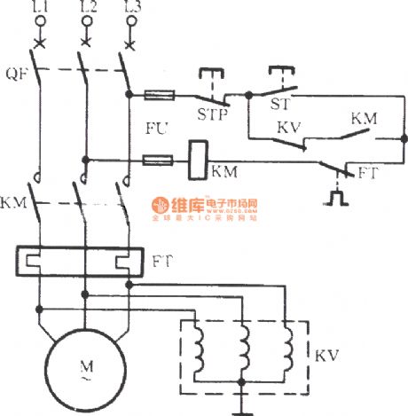
As the figure shows, the electromotor M is operating normally, the three coils of the relay KV are connected with the three-phase AC voltage respectively, the total synthesis suction of the three coils is zero, the contact point will not act. When one of the phases cuts off, the three-phase AC voltage is in the unbalance state to make the voltage relay act, it cuts off the coil power supply of KM, the electromotor M stops operating. The shortcoming of this circuit is that it can not prevent the broken phase of the internal winding of the electromotor M.
(View)
View full Circuit Diagram | Comments | Reading(2019)
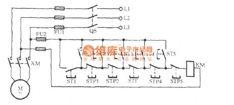
The electromotor controlled by five ST-microelectronics
Published:2011/8/30 2:16:00 Author:Christina | Keyword: electromotor, five ST-microelectronics
View full Circuit Diagram | Comments | Reading(835)
Acousto-optic double-control two-way water color-light music sound circuit
Published:2011/8/30 1:58:00 Author:Christina | Keyword: Acousto-optic, double-control, two-way, water, color-light, music, sound circuit
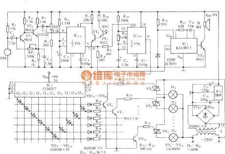
As the figure shows, it is composed of the voice-activated electronic switch, the light control switch, the monostable trigger, the controlled multi-vibrator, the music sound circuit, the count / cycle pulse distribution circuit, the six channels color light driving circuit and the AC step-down rectifier circuit. It has the two-way running water function, and it has some sweet songs.
(View)
View full Circuit Diagram | Comments | Reading(1775)
Sound and light double control electrical switch socket circuit
Published:2011/8/30 2:00:00 Author:Christina | Keyword: Sound, light, double control, electrical switch, socket circuit
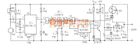
As the figure shows, it is composed of the acoustic/electric transducer sensing switch, the light control switch, the SCR control circuit, the music sound circuit and the AC step-down rectifier circuit.
(View)
View full Circuit Diagram | Comments | Reading(1408)
Sound control electric fan speed governing and the cricket voice control circuit
Published:2011/8/30 2:07:00 Author:Christina | Keyword: Sound control, electric fan, speed governing, cricket voice, control circuit
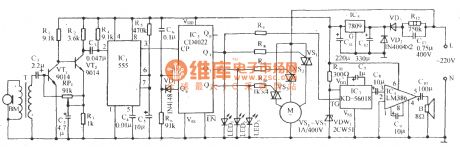
As the figure shows, it is composed of the sound control sensor, the audio-frequency amplifier, the monostable trigger circuit, the pulse count/distribution circuit, the SCR speed control circuit, the cricket sound circuit and the AC step-down rectifier circuit. This circuit uses the triggering sound control mode, and it has the three-stage wind-speed control and stalled control functions, when the fan is blowing, there is the sound of cricket. It has strong anti-interference characteristic.
(View)
View full Circuit Diagram | Comments | Reading(1898)
Voice control core circuit
Published:2011/8/30 2:12:00 Author:Christina | Keyword: Voice control, core circuit
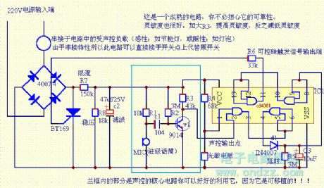
This is a mature circuit, you don't have to worry about its reliability.
The sensitivity is very good, you can improve the sensitivity by increasing the value of R3, also you can reduce the sensitivity by reducing the value of R3. The core circuit is in the blue box, you can make good use of it, because it is transplantable.
(View)
View full Circuit Diagram | Comments | Reading(915)
Sound and light double control eight-channel color light 12 songs sound circuit BH-SH-II
Published:2011/8/30 2:23:00 Author:Christina | Keyword: Sound, light, double control, eight-channel, color light, 12 songs, sound circuit
As the figure shows, it is composed of the voice-activated electronic switch, the light control switch, the music sound circuit, the audio power amplifier circuit, the multivibrator, the time order distribution circuit, the audio control switch circuit, the SCR drive circuit and the AC step-down rectifier circuit. When the circuit is playing the world famous songs, the eight-channel color light will send out the synchronous flash light.
(View)
View full Circuit Diagram | Comments | Reading(1668)
Electrothermal office desk plate automatic switch circuit
Published:2011/8/24 21:06:00 Author:Christina | Keyword: Electrothermal, office, desk plate, automatic switch
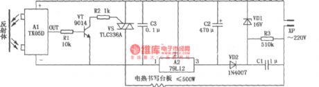
The electrothermal office desk plate automatic switch circuit is as shown in the figure, this device is composed of the ordinary electrothermal office desk plate and the infrared reflected type automatic switch which is composed of the TX05D, it has the automatic electricity heating function when someone is working on the desk, and also it has the function of automatic power off when no one is there. So it can save the electric energy, avoid the frequently plugfest, extend the service life of electrothermal office desk plate and prevent the accidents, it can be used on the ordinary electrothermal office desk plate, it is easy to make and very reliable.
(View)
View full Circuit Diagram | Comments | Reading(774)
Agricultural submersible pump anti-theft alarm
Published:2011/8/9 0:05:00 Author:Felicity | Keyword: anti-theft alarm, agricultural submersible pump
When the switch Q turns and the pump havn’t been started,the power transformer T is on.And the induced current produced by the secondary winding goes through the normally open contact of the AC contactor KM, the start-up button,and the stator winding of motor m to form a circuit. And then relay K switches on ,and the normally open contact releases to cut off the power circuit of coil KM and alarm HA. When the line is cut because of the pump being stolen or somehow,the power circuit of relay K will be cut off and its normally close contact closes and HA send alarm. (View)
View full Circuit Diagram | Comments | Reading(3461)
The circuit diagram of a load-driving multiplier (MPY600)
Published:2011/8/9 2:57:00 Author:Felicity | Keyword: load-driving multiplier
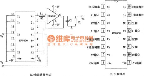
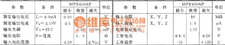
The circuit of a load-driving multiplier consists of multiplier MPY600 and high speed cache OPA633 is shown in fig(a). The relationship between input and output : Vo=VxVy/2. The voltage output by high speed cache OPA633 can drive capacitive load.MPY600 is wide bandwith multiplier, and the features are:1 High bandwidth: current output:75MHz, voltage output 30MHz2 Low noises3 Low feedthrough4 The datum output is GND5 Low misalignment voltage.
(View)
View full Circuit Diagram | Comments | Reading(895)
The circuit diagram of high Q notch filter
Published:2011/8/9 3:28:00 Author:Felicity | Keyword: high Q notch filter
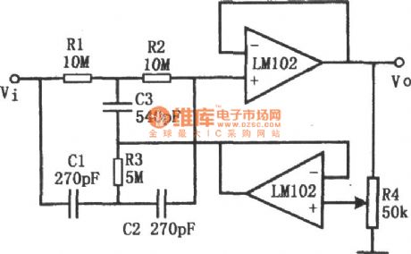
This figure shows the circuit of high Q notch filter. The operational amplifier in the low figure comprise voltage follower. The potentiometer R4 can change the value of Q (from 0.3 to 50). And the notch frequency : f0=1/2πR1C1. To avoid the drifting of f0, silvering mica or carbonate capacitor and matallic film resistance are needed. To reach 60dB attenuation, the allowance of resistance is below 0.1% ,and the allowance of capacity is below. To make LM102 work steadily, a 0.01μF capacitor is needed to filter the power. (View)
View full Circuit Diagram | Comments | Reading(1690)
Hum Filter (741) Circuit
Published:2011/8/9 23:25:00 Author:Felicity | Keyword: Hum Filter
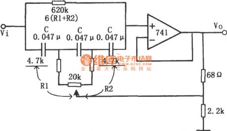
The Hum Filter Circuit is showed in the picture. The circuit is an economical narrow-band notch filter. It does not need elements of high accuracy. The frequency can be changed from 50Hz to 60Hz. It is used to eliminate the useless signal and hum in the audio and test instrumentation system. Differential feedback overhead active RC network is used in the circuit. The Notch Bandwidth depends on the feedback value. The Notch Bandwidth is narrow when the feedback value is high. Use the element value in the picture to adjust the potentiometer. It can adjust the frequency to 50Hz or 60Hz. The suppression of hum can reach the value of 30dB. When the frequency is 50Hz the bandwidth is 14Hz. When the frequency is 60Hz the bandwidth is 18Hz. The attenuation of signal is less than 1dB. (View)
View full Circuit Diagram | Comments | Reading(2381)
Infrared automatic faucet controller (555, LM567, SP110)
Published:2011/8/25 21:08:00 Author:TaoXi | Keyword: Infrared, automatic, faucet, controller
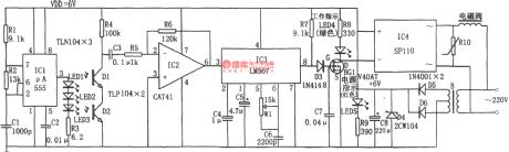
The infrared automatic faucet controller is as shown in the figure. This control circuit has the transmitter circuit and the receiver decoding control circuit. The transmitter circuit is composed of the multivibrator and the infrared emitting diode, the receiving circuit is composed of the infrared receiving tubes D1 and D2, the operational amplifier IC2(CA741), the audio decoder IC3 (LM567), the AC solid-state relay IC4(SP110), the power supply circuit. In the transmitter circuit, the multivibrator is composed of the IC1 (555) and R1, R2, C1, the oscillation frequency f=1.44/(R1+2R2)C1, in this figure, the corresponding frequency is about 40kHz.
(View)
View full Circuit Diagram | Comments | Reading(3056)
NFB type tone control circuit
Published:2011/8/25 21:16:00 Author:TaoXi | Keyword: NFB type, tone control
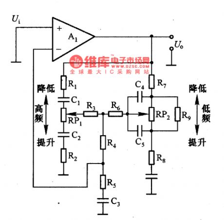
The NFB type tone control circuit is as shown in the figure. This kind of circuit has low output impedance and high input impedance, so it has the good S/N and low distortion characteristics. The control potentiometer need to use the C type potentiometer.
(View)
View full Circuit Diagram | Comments | Reading(1715)
| Pages:82/312 At 2081828384858687888990919293949596979899100Under 20 |
Circuit Categories
power supply circuit
Amplifier Circuit
Basic Circuit
LED and Light Circuit
Sensor Circuit
Signal Processing
Electrical Equipment Circuit
Control Circuit
Remote Control Circuit
A/D-D/A Converter Circuit
Audio Circuit
Measuring and Test Circuit
Communication Circuit
Computer-Related Circuit
555 Circuit
Automotive Circuit
Repairing Circuit