
Control Circuit
Index 94
500_MICROAMP_AT_30_TO_30000_CPS
Published:2009/7/14 21:47:00 Author:Jessie
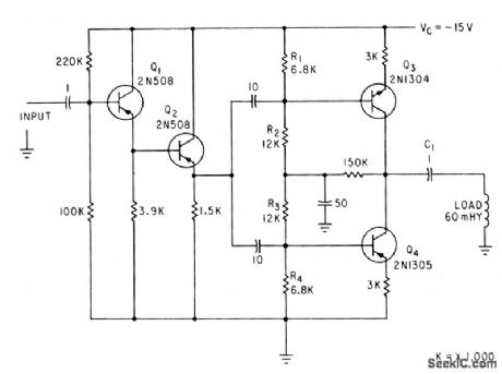
Used to drive 60-mh transducer at constant current without allowing d-c through transducer. Achieved by biasing Q3 and Q4 on all the lime, so each acts as collector resistance for the other.-S. Sokol, Transistor Pair Provides Constant-Current Drive, Electronics, 35:38, p 56. (View)
View full Circuit Diagram | Comments | Reading(790)
SAFE_SWITCHING_OF_SOLENOIDS
Published:2009/7/14 22:05:00 Author:Jessie
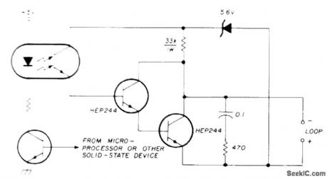
Optoisolator provides protective interface between teleprinter and 8080A or other microprocessor when switching inductive loads of teleprinter RC filter across Darlington pair speeds release time of print magnets.-T. C. McDermott, Switching Inductive Loads with Solid-State Devices, Ham Radio, June 1978, p 99-100. (View)
View full Circuit Diagram | Comments | Reading(955)
10_DIGIT_CODED_SWITCH
Published:2009/7/14 22:03:00 Author:Jessie
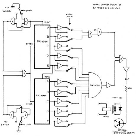
Uses seven Texas Instruments positive-logic chips,NAND gates 1-4 and 5-8 are from two SN7400N packages, Two SN7404N packages each provide six of inverting opamps shown Desired coda is set up as combination of 0s and 1s byρresetting ten 2-position switches. To open lock, switches at input for 0 and 1 must be pushed in Sequence of code Arrangement gives 1024 possible combinations but provides much greater protection unless intruder knows that 10 digits are required. Article describes operation of circuit. One requirement of the 2N7496N shift registers is that information be present at serial input before clocking pulse occurs.-K. E. Potter, Ten-Digit Code-Operated Switch or combination Lock, Wireless World, May 1974, P 123. (View)
View full Circuit Diagram | Comments | Reading(1517)
CRYSTAL_LAPPING_CONTROL
Published:2009/7/14 22:25:00 Author:Jessie
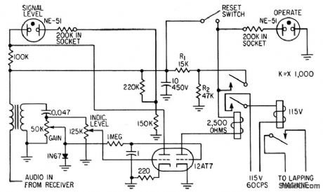
Noise signal generated by crystals being lapped is amp lified by receiver. Noise peak, which occurs whom crystal thickness produces frequency to which receiver is tuned, triggers circuit that automatically shuts down lapping machine. Useful for crystals up to 14 Mc.-J. F.Brumach, R. E. Bennett, and R.P. Chalker, Trigger Circuit Controls Quartz Crystal Lapping, Electronics, 31;29, p 66-67, (View)
View full Circuit Diagram | Comments | Reading(702)
150_MHZ_VIDEO_LINE_DRIVER
Published:2009/7/14 22:31:00 Author:Jessie
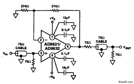
This line driven uses an Analog Devices P/N AD9631/9632 and has a bandwidth of better than 150 MHz (View)
View full Circuit Diagram | Comments | Reading(685)
LOW_VOLTAGE_ALARM
Published:2009/7/14 21:33:00 Author:May
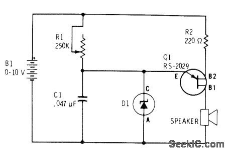
UJT relaxation oscillator produces audio tone from loudspeaker when battery voltage drops below breakdown voltage of zener. For 9-V battery, zener can be 6-V unit (Radio Shack 276-561), When input voltage drops below zener breakdown, zener stops conducting and C1 begins charging, as required for oscillation. When battery is replaced, zener breaks down and prevents C1 from charging.-F. M. Mims, Semiconductor Projects, Vol. 2, Radio Shack, Fort Worth, TX, 1976, p 43-49.
(View)
View full Circuit Diagram | Comments | Reading(0)
AC_LINE_MONITOR
Published:2009/7/14 22:33:00 Author:Jessie
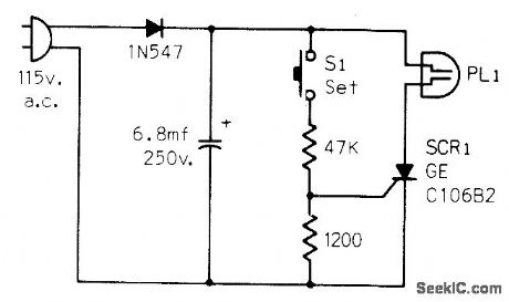
Detects AC line failures of any duration and turns off neon lamp PL1 to indicate that clocks require resetting. Circuit is plugged into AC outlet, and S1 is pushed to trigger SCR on and send current through lamp.-J. R. Nelson, Some Ideas for Monitoring A.C. Power Lines, CQ, July 1973, p 56. (View)
View full Circuit Diagram | Comments | Reading(1182)
VIDEO_OPERATED_CONTROLLER
Published:2009/7/14 22:33:00 Author:Jessie
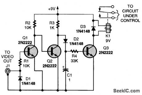
If you need a timer that is programmable, precise, and will provide long delays, almost any VCR can be used without any internal modification. All that is required is a circuit that will detect the presence of the video output signal when the recorder turns on. The first diode (D1) clamps the negative video to ground. The rest of the circuit responds to the frame markers to charge up the capacitor and turn on the relay. A tape isn't even required (in most cases) if the recorder is tuned to an active channel because the video-out signal appears as soon as the recorder is turned on. Therefore, the circuit's ON time is not limited by tape length. (View)
View full Circuit Diagram | Comments | Reading(913)
MULTICHANNEL_ALARM
Published:2009/7/14 21:25:00 Author:May
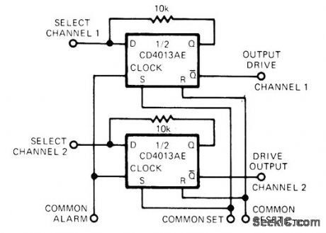
Half of CD4013AE flip-flop serves as latching AND gate in each channel being monitored for vervoltage, overtemperature, or any other out-of-tolerance condition that can be represented by logic 1 level applied to terminal that connects to clock inputs of all flip-flops. Any number of additional channels can be paralleled to Gammon terminals. Each channel has own transistor driver and either LED or audio alarm. Alarm condition is held until operator resets system by applying voltage to common set terminal. Article shows how to obtain additional flexibility by adding NAND and AND gates to each select input and to common alarm input.-J. C. Nichols, CM0S D Flop Makes Latching AND Gate, EDN Magazine, April20, 1974, p 89 and 91. (View)
View full Circuit Diagram | Comments | Reading(1163)
OVERVOLTAGE_ALARM
Published:2009/7/14 21:24:00 Author:May
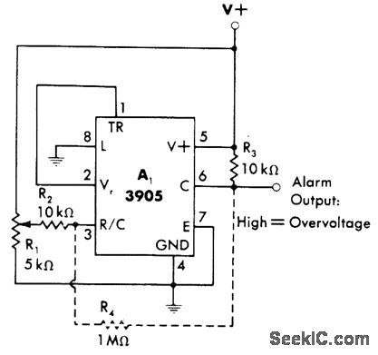
Connection shown for 3905 timer makes output go high for energizing suitable alarm when supply voltage rises above predetermined level. Timer is connected as noninverting comparator that compares its fixed voltage-comparison threshold of 2 V with fraction of supply voltage determined by setting of R1. Optional resistor R4 can be added if some hysteresis is desirable to prevent tripping of alarm by momentary fluctuations of supply.-W. G. Jung, IC Timer Cookbook, Howard W, Sams, Indianapolis, IN, 1977, p 230-231. (View)
View full Circuit Diagram | Comments | Reading(983)
POWER_FAILURE_ALARM
Published:2009/7/14 21:23:00 Author:May
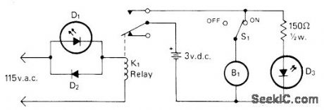
POWER-FAILURE ALARM-Buzzer sounds and red LED D3 comes on when AC power fails, as reminder that clocks will need resetting. Green LED D1 indicates that alarm is plugged in, D2 is Radio Shack 276-1103 or equivalent silicon diode. B1 is 1.5-6 VDC Radio Shack 273-004 or equivalent buzzer, and K1 is Radio Shack 275-211 or equivalent 117-VAC SPDT relay.-C. R. Graf, The Powerlarm, CQ, Feb. 1977, p 47 and 73. (View)
View full Circuit Diagram | Comments | Reading(0)
TOUCH_TONE_IC
Published:2009/7/14 21:14:00 Author:May
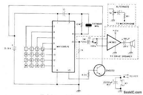
MOSTEK MK5085/6 IC and keyboard together form inexpensive Touch-Tone generator producing tones within 0.75% of required values. Uses 3.579545-MHz TV color-burst crystal. Pin 15 is grounded to provide dual tones only .Pin 10 provides output when keyboard entry has been made ,for keying push-to-talk (PTT) Loudspeaker can be eliminated if output if fed directly into microphone input of transmitter. Choice of IC depends on type of keyboard used.-T. Ahrens, Integrated-Circuit Tone Generator, Ham Radio, Feb. 1977, p70. (View)
View full Circuit Diagram | Comments | Reading(3011)
TOUCH_SWITCH_II
Published:2009/7/14 19:57:00 Author:May
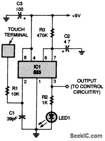
IC1, a 555 timer, is connected in a one-shot multivibrator circuit that is triggered by touching the touch terminal. The timed ON period is about 4 seconds with the component values given. To increase the ON time, increase the value of R3 or C2; to decrease the ON time, reduce the value of R3 or C2. The 9-V output at IC1 pin 3 can be used to drive an optocoupler, a power transistor, a hexFET transistor, CMOS circuitry, and more. (View)
View full Circuit Diagram | Comments | Reading(0)
UNDERVOLTAGE_ALARM
Published:2009/7/14 20:56:00 Author:May
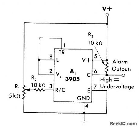
3905 timer output goes high when power supply drops below predetermined voltage level. Timer is connected as inverting comparator that compares fraction of supply voltage (as set by R1) with fixed voltage-comparison threshold of 2 V for timer. Output can be used to drive suitable alarm indicator.-W. G. Jung, IC Timer Cookbook, Howard W. Sams, Indianapolis, IN, 1977, p 230-231. (View)
View full Circuit Diagram | Comments | Reading(1285)
DOUBLING_CONTROL_RANGE
Published:2009/7/14 20:45:00 Author:May
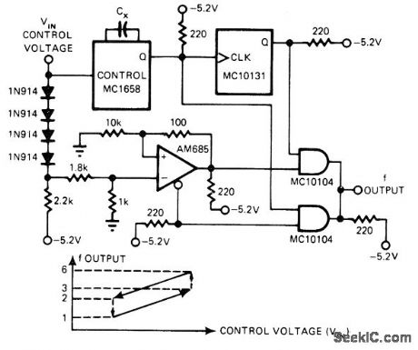
Circuit doubles frequency-deviation ratio of given VCO. Control voltage of MC1658 VCO, with range of 0 to -2 V, is attenuated and then applied to AM685 opamp comparator. When control voltage reaches an extreme and crosses over amplifier's reference voltage, detector switches to opposite state. Circuit output is thus either that of VCO or VCO divided by 2. Article describes op-eration in detaiL-E. Kane, Expander Doubles VCO Frequency Deviation, EDN Magazine, Jan. 20, 1977, p 94. (View)
View full Circuit Diagram | Comments | Reading(858)
TUNING_BY_REACTANCE_SWITCHING
Published:2009/7/14 20:31:00 Author:May
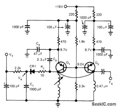
Tuning voltage V, in range of 0 to 7 V changes effective capacitance during peak positive portion of collector voltage cycle, to provide tuning over range of about 90 to 150 MHz. Reactance-switching HP 5082-3188 diode CR1 switches in additional capacitance for oscillator using Motorola 2N5208 transistors.-C. Weber, VCO Reactance Switching Provides Broad Tuning Range, EDN Magazine, March 20, 1977, p 151 and 153. (View)
View full Circuit Diagram | Comments | Reading(819)
TOUCH_SWITCH_Ⅲ
Published:2009/7/14 20:14:00 Author:May
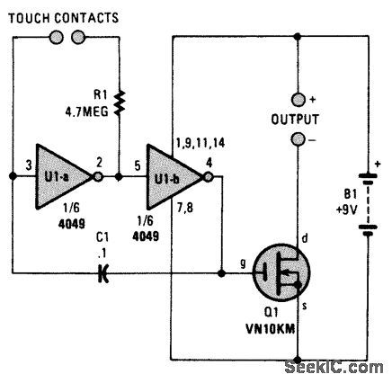
The touch switch shown uses 9-Vdc operation, rather than the commonly used 120-Vac. (View)
View full Circuit Diagram | Comments | Reading(803)
SIMPLE_TOUCH_SWITCH
Published:2009/7/14 20:13:00 Author:May
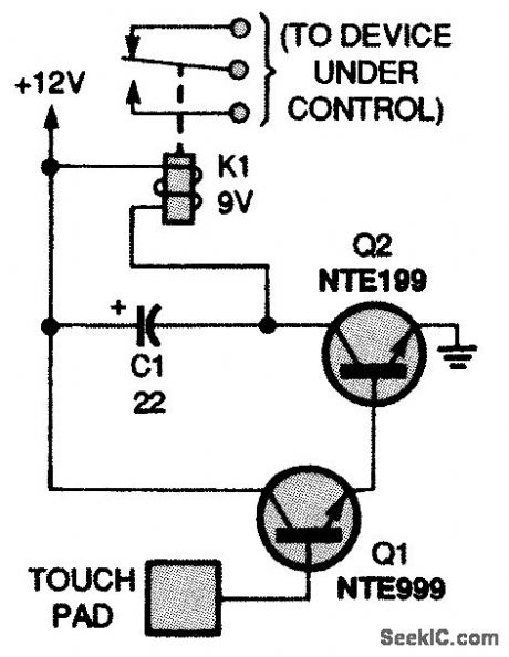
This circuit has two high-gain transistors. Operation occurs when the ambient 60-Hz ac field is impressed on the touch pad during the finger contact. The signal turns on Q1, causing Q2 to energize the relay. Capacitor C1 is used to prevent the relay from oscillating. (View)
View full Circuit Diagram | Comments | Reading(0)
ALTERNATIVE_LIGHT_OPERATED_TURNOFF_TOUCH_SWITCH
Published:2009/7/14 20:11:00 Author:May
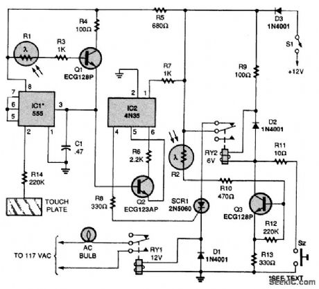
When the touch plate is touched, it turns the output of IC1 on, giving a positive potential to the base of Q2. In turn, that turns on pins 4, 5, and 6 of IC2, triggering the SCR's gate and energizing RY1.When RY1 is energized, its contacts pull in, turning on the ac bulb. When R1 is hit by a strong light, it turns on the SCR and energizes RY1. To turn the ac bulb off, just point a strong flashlight at R2; this decreases the base resistance of Q3, making its base positive and, therefore, energizing RY2. When the contact of RY2 pulls in, it disconnects the anode of the SCR from the positive supply, turning it off. Or you can press S2 to energize RY2 and turn off the ac bulb (View)
View full Circuit Diagram | Comments | Reading(1699)
SWITCH_OPERATED_TURNOFF_TOUCH_SWITCH
Published:2009/7/14 20:08:00 Author:May
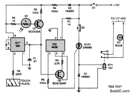
When S1 is closed,the circuitry is on in standby mode.When the touch plate is touched,the output of the 555 time IC1 goes high,supplying a positive potential to the base of transistor Q2,aiding its bias,The transistor is then on,allowing current to flow through pin4,5 and 6 of IC2.The gate of the SCR is then triggered,the relay is energized,and its contacts turn the ac bulb on.To turn the bulb off,just press S2(RESET),which disconnects the ande of the SCR from the positive supply,turning it off and deenergizing the relay,The light-dependent resistor(R7)is used if you want to turn on the circuit remotely.Just point a flashinght at R7 to decrease its resistance,leaving only the 1000Ω resistor as the base resistance.The resistance give the base a positive positive potential,forward biasing the emitter-base junction of transistor Q1.Transistor Q2 is also turned on because its base is made positive by Q1,which triggers SCR1,energizing the relay.
(View)
View full Circuit Diagram | Comments | Reading(1478)
| Pages:94/312 At 2081828384858687888990919293949596979899100Under 20 |
Circuit Categories
power supply circuit
Amplifier Circuit
Basic Circuit
LED and Light Circuit
Sensor Circuit
Signal Processing
Electrical Equipment Circuit
Control Circuit
Remote Control Circuit
A/D-D/A Converter Circuit
Audio Circuit
Measuring and Test Circuit
Communication Circuit
Computer-Related Circuit
555 Circuit
Automotive Circuit
Repairing Circuit