
Control Circuit
Index 83
RC type tone control circuit
Published:2011/8/25 21:23:00 Author:TaoXi | Keyword: RC type, tone control
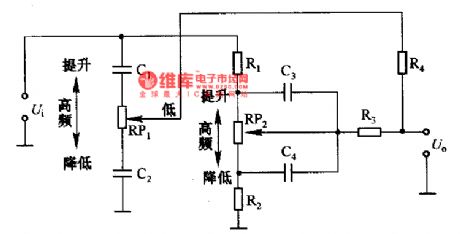
The RC type tone control circuit is as shown in the figure. The tone control circuits are divided into the RC type, the input series voltage feedback NFB type, the input parallel voltage feedback BAX type. The RC type tone control circuit which is as shown in figure 2-42 is composed of the low-pass filter and high-pass filter (composed of the capacitor and resistor), the filter characteristics is controlled by the potentiometer. This kind of circuit has the low input impedance and higher output consumption, so you need to connected the buffer amplifier with it. The rated consumption of the filter is about 15-20dB, so the input buffer need to have the wide dynamic range.
(View)
View full Circuit Diagram | Comments | Reading(1331)
Multi-functional remote control circuit (555, LM909)
Published:2011/8/26 0:56:00 Author:TaoXi | Keyword: Multi-functional, remote control
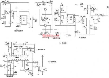
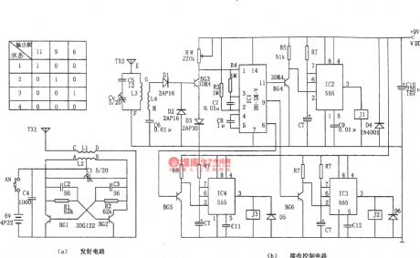
The multi-functional remote control circuit is as shown in the figure, this circuit is composed of the generator and receiver. The transmitter is composed of the astable multivibrator, the audio-frequency generator and the RF oscillator. The receiver uses the LM909. The multivibrator is composed of the IC1 (555) and R1, R2, R3, C3, you can change the charging and discharging time constant by using the switch K1. When K1 is in the position 1 , the duty cycle D=(R2+R3)/(R1+R2+R3+R4)≈60%; when K1 is in the position 2 , the duty cycle D=(R2+R3)/(R1+R2+R3+R4)≈30%; When K1 is in the position 3 , the duty cycle D=(R2+R3)/(R1+R2+R3+R4)≈100%(pin-3 of IC1 outputs the low level signal).
(View)
View full Circuit Diagram | Comments | Reading(2153)
Power control circuit with the thyristor
Published:2011/8/25 21:28:00 Author:TaoXi | Keyword: Power control circuit, thyristor
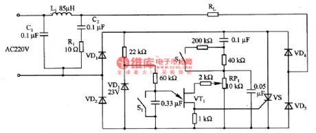
The power control circuit with the thyristor is as shown in the figure, the circuit uses the L1, C1, C2 and R2 to form the filter circuit, and it can be used to filter the power supply noise. The rectifier and voltage regulator circuit is composed of the VDl, VD2 and VD3, it can supply the operating voltage for the control circuit. The trigger circuit of the thyristor VS is composed of the VT1 and the surrounding components. The thyristor VS controls the voltage of the load.
(View)
View full Circuit Diagram | Comments | Reading(1777)
Electromotor constant speed control circuit composed of the CA0358
Published:2011/8/25 22:03:00 Author:TaoXi | Keyword: Electromotor, constant speed, control circuit
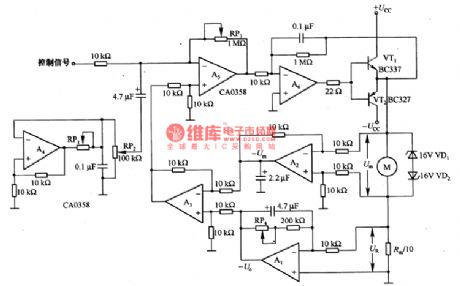
The Electromotor constant speed control circuit composed of the CA0358 is as shown in the figure. In the circuit, the differential amplifier A2 detects the ends voltage Um of the electromotor, A2 adds the output voltage Um to the inverting input port of the differential amplifier A3. At the same time, the A1 detects the ends voltage of Rm/10 (Rm is the DC resistance of the electromotor armature) UR, and it amplifies the voltage to 10 times. The voltage adds to the in-phase input port of A3. RP4 can be used to adjust the magnification of A1. You need to make the electromotor break away from the power circuit and make it stop working, you can adjust the RP4 until the A3's output is zero.
(View)
View full Circuit Diagram | Comments | Reading(1434)
Remote control multi-file controller
Published:2011/8/25 22:42:00 Author:TaoXi | Keyword: Remote control, multi-file, controller
The remote control multi-file controller is as shown in the figure. This circuit has the radio transmitter and the wireless receiving and controller parts. The generator is the self-excited multivibrator circuit. The oscillation frequency f=l.44/(R1C2+R2C3). The controller uses the 30~40MHz amateur frequency range. The frequency selection circuit of the receiver outputs the high-frequency signal, and this signal is rectified by D1 and D2, and it also amplified by BG3 to be sent to the pin-1 of IC1. The IC1 uses the BH-SK-V type integrated package, it has the level 2 high power gain amplifier, the frequency selector, the plastic device and the trigger, driver.
(View)
View full Circuit Diagram | Comments | Reading(766)
Decorative light controller composed of the Y977A/B
Published:2011/8/26 3:29:00 Author:TaoXi | Keyword: Decorative light, controller
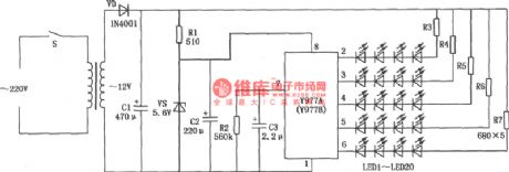
View full Circuit Diagram | Comments | Reading(994)
The 300MSPS high-speed 10-bit D/A converter AD9751
Published:2011/8/23 22:39:00 Author:qqtang | Keyword: 300MSPS, D/A converter
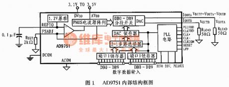

AD9751 is produced with advanced low-cost 0.35mm CMOS skill. It can work under the voltage of 2.7V~3.6V and its power consumption is lower than 300mW. The features of AD9751 are as follows:It is one of high-speed TxDAC+s, and it is compatible with pins of other chips, it can provide with resolution ratios of 10, 12 and 14-bit.It has an ultra-high-speed converter ratio of 300MSPS.It has a dual 10-bit lock storage and multi-line multiplex input terminal.It contains the clock multipler, which can be input with differentiation and single terminal clock.
(View)
View full Circuit Diagram | Comments | Reading(798)
Brake light monitoring circuit
Published:2011/8/26 3:30:00 Author:TaoXi | Keyword: Brake light, monitoring circuit

View full Circuit Diagram | Comments | Reading(817)
The SPT1141/1151 multi-functional switch controller application circuit
Published:2011/8/13 1:31:00 Author:qqtang | Keyword: multi-functional switch controller, application circuit
View full Circuit Diagram | Comments | Reading(697)
The MAX639 multi-functional switch integrated stabilizer
Published:2011/8/23 22:36:00 Author:qqtang | Keyword: multi-functional switch, integrated stabilizer
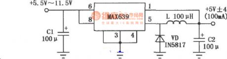
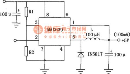
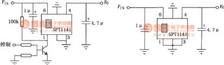
The solid/adjustable output multi-functional switch stabilizing integrated circuit is a high-efficient and multi-functional switch stabilizer circuit, whose output voltage is +5V, input voltage is 6.5~11.5V, output current is 100mA. Its efficiency is high, and it is fixed with the e-switch control terminal and battery low voltage test terminal which are controlled by the logic LEV, it characterizes low consumption, low voltage difference and strong functions,etc. The circuit is used in portable devices and instruments, etc, whose basic usage is shown in the figure.
(View)
View full Circuit Diagram | Comments | Reading(978)
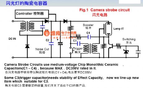
The digital camera special circuit
Published:2011/8/13 1:07:00 Author:qqtang | Keyword: digital camera, special circuit
View full Circuit Diagram | Comments | Reading(1018)
The remote control TX3004
Published:2011/8/4 0:54:00 Author:Seven | Keyword: remote control

Code type: encode/decode PT2260/PT2262 (weld plate); study code eV1527/PT2240B; roll code HCS101/HCS301; The features of the product:Low price, small-sized emitter handle, fine outline, energy-saveing, reliable working, black surface. The symbol of the rubber cushion can be set according to the need.Application range:Motor alarm product, car alarm product, domestic alarm product, short-distance wireless control product, remote control garage door, remote control electric curtain door/window, collapsible door, remote control sliding gate and industrial control, etc. (View)
View full Circuit Diagram | Comments | Reading(1203)
Once timer controller 5
Published:2011/8/8 21:10:00 Author:Ecco | Keyword: Once timer controller
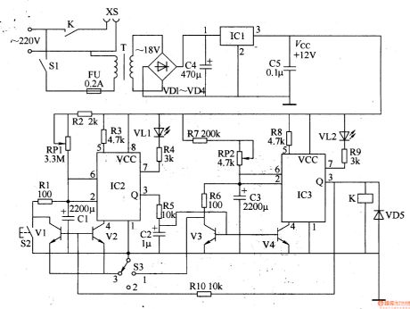
The once timer controller circuit is composed of the power supply circuit and timing control circuit, and it is shown in Figure 3-87. Power supply circuit is composed of the power switch Sl, fuse FU, power transformer T, rectifier diodes VDl-VD4, filter capacitors C4, C5, and three-terminal voltage regulator integrated circuit ICl. Timing control circuit is composed of the time-base circuits IC2, 1C3, resistors Rl-RlO, capacitors Cl-C3, potentiometers RPl, RP2, transistors Vl-V4, light-emitting diodes VLl, VL2, diode VD5, manual discharge button S2, function selector switch S3 and the relay K.
(View)
View full Circuit Diagram | Comments | Reading(1006)
Brood thermostat
Published:2011/8/10 3:48:00 Author:Ecco | Keyword: Brood thermostat
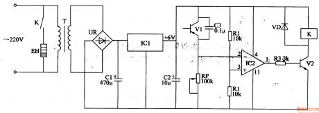
The brood thermostat circuit is composed of the power supply circuit and temperature detection control circuit, and it is shown in Figure 4-41. Power supply circuit is composed of the power transformer T, bridge rectifier UR, filter capacitors Cl, C2, and three-terminal voltage regulator integrated circuit ICl. Temperature detection control circuit consists of transistors Vl, V2, resistors Rl-R3, potentiometer RP, capacitor C3, diode VD, operational amplifier integrated circuit IC2, heater EH and relay K. Rl-R3 use 1/4W metal film resistors or carbon film resistors. C3 uses the monolithic capacitor or polyester capacitor.
(View)
View full Circuit Diagram | Comments | Reading(1415)
Fish hatching pool controller 2
Published:2011/8/10 3:44:00 Author:Ecco | Keyword: Fish hatching pool controller
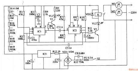
The fish hatching controller circuit is composed of the power supply circuit, time control circuit, working status indication circuit and control implementation of circuit, and it is shown in Figure 4-25. The power supply circuit consists of the step-down capacitor C8, resistors Rl2, R13, rectifier diodes VDl-VD4, three-terminal integrated voltage regulator IC3, and filter capacitors C6, C7 and so on. Time control circuit is composed of the quench time control circuit switch Sl, resistors R14-R19, Rl-R4, time-base integrated circuit IC1 and capacitors Cl, C2 and so on. Rl-Rll and R14-Rl9 select the 1/4W carbon film resistors.
(View)
View full Circuit Diagram | Comments | Reading(830)
Fish hatching pool controller 1
Published:2011/8/10 3:41:00 Author:Ecco | Keyword: Fish hatching pool, controller
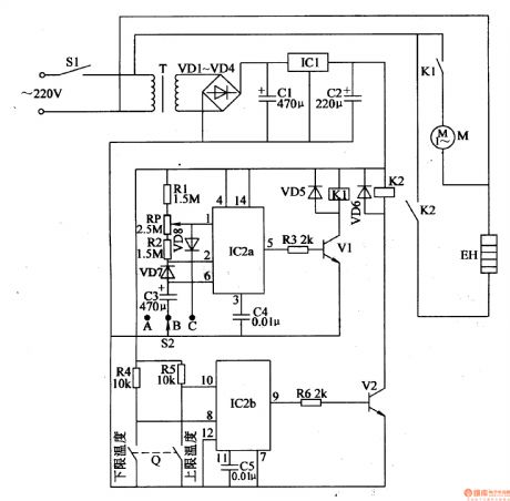
The fish hatching controller circuit is composed of the power supply circuit, oxygen pump automatic control circuit and water temperature automatic control circuit, and it is shown in Figure 4-24. Power supply circuit is composed of the power switch Sl, power transformer T, rectifier diodes VDl-VD4, three-terminal regulator ICl and filter capacitors Cl, C2 and so on. Oxygen pump automatic control circuit consists of the oxygen pump motor M, selector switch S2, relay Kl, driver transistor Vl, and the time-base integrated circuit IC2a and external RC components. Automatic temperature control circuit is composed of the electric heater EH, relay K2, drive transistor V2, time-base integrated circuit IC2b, the electric contact thermometer Q and external RC components.
(View)
View full Circuit Diagram | Comments | Reading(1218)
Fish farming thermostat controller 2
Published:2011/8/8 21:52:00 Author:Ecco | Keyword: Fish farming, thermostat controller
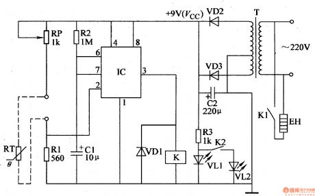
The fish farming thermostat controller circuit is composed of the power supply circuit and temperature detection control circuit, and it is shown in Figure 4-23. Power supply circuit is composed of the power transformer T, rectifier diodes VD2, VD3, filter capacitor C2, limiting resistor R3 and power indicator LED VLl. Temperature detection control circuit consists of the thermistor RT, resistors Rl, R2, capacitor Cl, potentiometer RP, time-base integrated circuit IC, heating working indicating light-emitting diode Vm, relay K and diode VDl. Rl-R3 use 1/4W metal film resistors or carbon film resistors.
(View)
View full Circuit Diagram | Comments | Reading(2090)
Fish farming thermostat controller 1
Published:2011/8/8 21:48:00 Author:Ecco | Keyword: Fish farming , thermostat controller
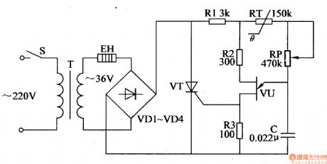
The fish farming thermostat controller circuit is composed of the power supply circuit and temperature control circuit, and it is shown in Figure 4-22. Power supply circuit consists of the power switch S, power transformer T, electric heater EH and rectifier diodes VDI-VD4. Temperature control circuit consists of the resistors Rl-R3, thermistor RT, potentiometer RP, capacitor C, single-junction transistor VU and thyristor VT. Rl select the 1/2W metal film resistor; R2 and R3 select the 1/4W metal film resistors or carbon film resistors. RP chooses the solid synthetic membrane potential potentiometer. C uses the monolithic capacitor or polyester capacitor.
(View)
View full Circuit Diagram | Comments | Reading(950)
Once timer controller 6
Published:2011/8/8 21:13:00 Author:Ecco | Keyword: Once timer controller
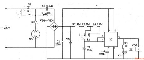
The once timer controller circuit is composed of the power supply circuit and timing control circuit, and it is shown in Figure 3-88. Power supply circuit is composed of the power control button Sl, normally open contact Kl of relay K, buck capacitor Cl, discharge resistor Rl, rectifier diodes VDl-VD4, filter capacitor C2 and zener diode V. Timing control circuit consists of the time-base integrated circuit IC, time delay selection switch S2, resistors R2-R5, capacitors C3, C4, light-emitting diode VL, relay K and diode VD5. Rl select the 1/2W metal film resistor.
(View)
View full Circuit Diagram | Comments | Reading(902)
Cycle timing controller 1
Published:2011/8/8 21:19:00 Author:Ecco | Keyword: Cycle timing controller
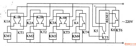
The cycle timing control circuit is composed of the digital delay relays KTl-KT5, time relay KT6 and AC contactors KMl-KM4, and it is shown in Figure 3-89. KTl-KW are used to control the conduction time of 4-way timing control circuit. KT5 (the set time is 4 hours, which is the total of 4-way conduction time) is used to reset KTl-KW and make them work in cycle; KT6 provides for the KT5 reset conditions. KTl-KT5 use the JSl4S digital delay relays; KT6 uses JSl4 time relay. KMl-KM4 select the 220V AC power relay.
(View)
View full Circuit Diagram | Comments | Reading(893)
| Pages:83/312 At 2081828384858687888990919293949596979899100Under 20 |
Circuit Categories
power supply circuit
Amplifier Circuit
Basic Circuit
LED and Light Circuit
Sensor Circuit
Signal Processing
Electrical Equipment Circuit
Control Circuit
Remote Control Circuit
A/D-D/A Converter Circuit
Audio Circuit
Measuring and Test Circuit
Communication Circuit
Computer-Related Circuit
555 Circuit
Automotive Circuit
Repairing Circuit