
Control Circuit
Index 90
The pyroelectric infrared sensing automatic door control and voice calling circuit HN911D
Published:2011/7/26 20:02:00 Author:TaoXi | Keyword: Pyroelectric, infrared sensing, automatic door control, voice calling
The circuit is as shown. It is composed of the pyroelectric infrared sensor module, the delay control network, the electric coupling & SCR control circuit, the language voice circuit, the AC step-down rectifier circuit.etc. The HN911D is one kind of pyroelectric infrared detector module.
(View)
View full Circuit Diagram | Comments | Reading(637)
The engine high temperature protector
Published:2011/8/3 22:16:00 Author:qqtang | Keyword: high temperature protector
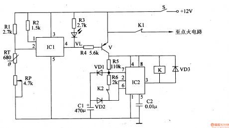
Here is to introduce an engine high temperature protector which can cut of the igniting power supply when the water in the tank is hotter than 90℃, so the car is stalled and protected, and the dangers caused by high heat can be avoided. The principle of the circuitThe engine high temperature protector consists of the temperature control circuit and protection control circuit, see as figure 7-159.
The temperature test controller circuit consists of the thermistor RT, potentiometer RP, resistor R1-R3, electric switch integrated circuit IC1 and heat alarm indicating LED VL. (View)
View full Circuit Diagram | Comments | Reading(836)
The automobile lighting lamp lifespan prolonging protector (2)
Published:2011/8/3 22:19:00 Author:qqtang | Keyword: lighting lamp, protector
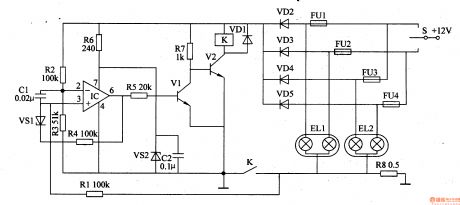
Here is to introduce an automobile lighting lamp lifespan prolonging protector which works in the current limiting method, when the lamp power supply is connected the current limit resistor is also linked, so the pulse current is limited, after dozens of ms of delay, and then after the control, the circuit will make the current limit resistor short automatically, so the lighting lamp will work normally, by which the lifespan of the lamp can be prolonged. The principle of the circut
The automobile lighting lamp bulb lifespan protector consists of the current test controller and control executing circuit, see as figure 7-158.
(View)
View full Circuit Diagram | Comments | Reading(692)
The automobile lighting lamp lifespan prolonging protector (1)
Published:2011/8/3 22:21:00 Author:qqtang | Keyword: lighting lamp, protector
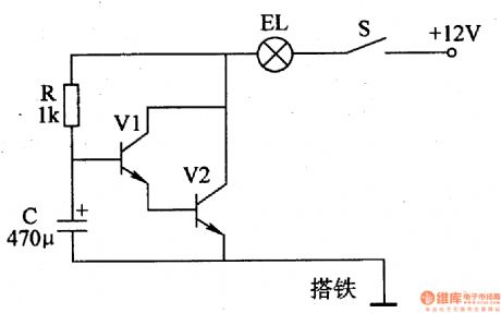
When the car or motorcycle lamp is impacted by the pulse current when it is in the cold state, it is easy to break. Here is to introduce the automobile lighting lamp lifespan prolonging protector which can pre-heat the bulb fuse and make the fuse current rise gradually from zero, so the bulb is prevented from being burned due to the impact current, so the lifespan of the bulb will be prolonged. The working principle of the circuit
The automobile lighting lamp bulb lifespan protector consists of the resistor R, capacitor C, transistor V1 and V2, see as figure 7-157.
(View)
View full Circuit Diagram | Comments | Reading(682)
The winding engine auto limit controller
Published:2011/8/3 23:08:00 Author:qqtang | Keyword: winding engine, auto limit controller
Theworkingprincipleofthecircuit
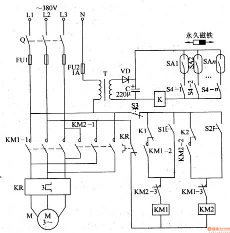
The winding engine auto limit controller circuit consists of the knife switch Q, fuses of FU1 and FU2, heat relay KR, relay K, AC contactors of KM1 and KM2, rising control key S1, dropping control key S2, stop button S3, button self-lock control switch S4(S4-1S4-n), reed pipe SAl-SAn, power supply transformer T, rectifier diode VD and filter capacitor C, see as figure 8-142.
After the AC 220V voltage between the phase wire L1 and neutral line L is stepped down by T, rectified by VD and filtered by C, it provides with 12V DC voltage for the relay K. (View)
View full Circuit Diagram | Comments | Reading(957)
Automatic night lighting light circuit composed of the μA555
Published:2011/8/2 4:22:00 Author:Christina | Keyword: Automatic lighting, light
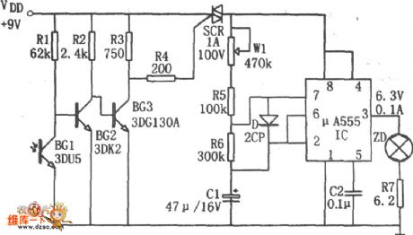
The automatic night lighting light circuit is as shown in the figure. This circuit is composed of the photoelectric switch, the multivibrator.etc. The multivibrator is composed of the W1, R5, R6, C1 and 555, the oscillation frequency f=1.44/(Rw1+R5+2R6)C1, the frequency is about 2-10 seconds, you can get the corresponding frequency by adjusting the potentiometer W1.
In the photoelectric switch, the BG1(3DU5) is the phototransistor, it has different resistance values in different illuminations. In the day time, the phototransistor has the low resistance because of the illumination, so the BG2 cuts off, the BG3 conducts, the SCR cuts off, the oscillator stops, the indicator light will not turn on.
(View)
View full Circuit Diagram | Comments | Reading(913)
MCl45027 general infrared, ultrasonic or RF remote control receiving decoder circuit
Published:2011/7/18 6:35:00 Author:Christina | Keyword: general, infrared, ultrasonic, RF, remote control, receiving decoder
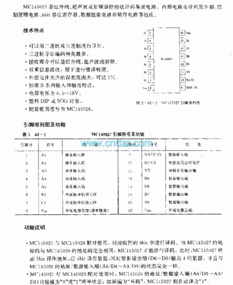
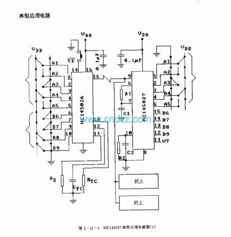
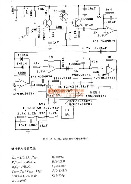
The MCl45027 is designed as one kind of general red-needle line, ultrasonic or RF remote control receiving decoder circuit. The internal circuit is composed of the sequence generator, the logic control circuit, the 4-bit shift register, the data extraction circuit and the latch circuit.etc.
Features
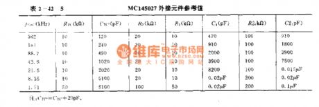
It uses the binary or ternary to find the address;The ternary addressing coding has the maximum species;The receive media can be the infrared, ultrasonic in the error detection;The permissible error range of the external components can be 5%;Standard B series input and output characteristics;The power voltage is 4.5-18V;Plastic DIP or SOG package;The matching model is MCl145026.
(View)
View full Circuit Diagram | Comments | Reading(695)
Thyristor SCR Controlled Rectifier Circuit
Published:2011/8/4 0:08:00 Author:Robert | Keyword: Thyristor, SCR, Controlled, Rectifier
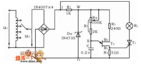
The controlled rectifier circuit's function is changing the AC power to the voltage-controlled DC power. The picture shows the single-phase half-controlled bridge rectifier testing circuit. The main circuit is made up of load RL (lamp) and thyristor T1. The trigger circuit is single-junction transistor T2 and a RC-bridge phase-shift trigger circuit which is made up of some RC elements. By change the thyristor T1's conduction angle it could adjust the main circuit's controlled output rectified voltage (or current)'s value. This could be seen from the variation of the brightness of the lamp load. The thyristor's conduction angle's value is determined by the trigger frequency f which could be calculated from the formula of f=(1/RC)ln(1/1-η). (View)
View full Circuit Diagram | Comments | Reading(1397)
Remote Temperature-Measurement Circuit Composed Of Intelligent Remote Thermal Fan Controller ADT7460
Published:2011/7/14 10:10:00 Author:Robert | Keyword: Remote, Temperature-Measurement, Intelligent, Thermal, Fan, Controller
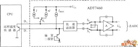
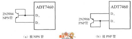
The remote temperature sensor is composed of ADT7460 with two transistors. As the transistor's emitter voltage is proportional to temperature, this feature could be used to measure the remote temperature. The remote temperature measurement circuit is shown in the picture. The CPU shown in the picture has the temperature-measurement transistor itself. It is equivalent to a 2N3906 PNP transistor. If using the discrete transistor, the collector polar can not be connected to ground and it should be connected to the base polar to be used as diode. If using the NPN transistor, it should connect the base polar to the D+ port, and connect the emitter polar to the D- port. If using the PNP transistor, it should connected the emitter polar to D+ port and connected the base polar to the D- polar. The picture shows the 2N3904 type NPN transistor and 2N3906 type PNP transistor's wiring mode. (View)
View full Circuit Diagram | Comments | Reading(817)
Solid-state relay basic wiring schematic diagram
Published:2011/8/8 0:21:00 Author:Sophia | Keyword: Solid-state relay, Wiring
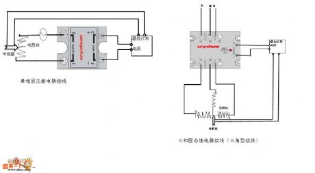
At present, solid-state relay has been applied to different industries. broadly speaking, solid-state relay includes several cpmtrol systems:
temperature control system, miniwatt motor control system, three-phrase electric machine regenerative control system, solenoid value control system, high frenquency system and so on. Butmany beginners and some engineers haven't engaged in these areas, so now I draw a simple wiring diagram for reference. (View)
View full Circuit Diagram | Comments | Reading(6779)
Touch relay switch circuit diagram
Published:2011/8/4 21:11:00 Author:Sophia | Keyword: Touch relay switch
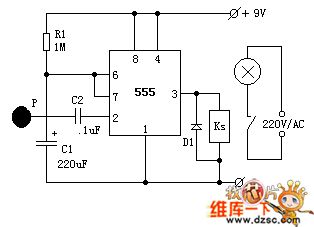
Touch delay switch circuit formed by the time base NE555 chip.
IC1 is a 555 timer circuit, which also becomes monostablecircuit. Usually because P-side of touching film doesn't have induced voltage, which make capacitor C1 discharge through the 7th foot of 555 , 3-pin output is low level. The relay KS is released, and light does not shine.
When you need to turn on the lights, we just touch the metal P with the hands. The noise signal voltage of the human sense is added from C2 to the trigger terminal of 555, which makes the output of 555 become high from low output, relay KS pull and light lightened. Meanwhile, the first 7 pin interior of 555 within is stoped, then the power charge to C1 through R1, and this is the beginning of time. (View)
View full Circuit Diagram | Comments | Reading(3952)
The 800MHZ FM circuit
Published:2011/7/29 4:36:00 Author:Borg | Keyword: FM circuit
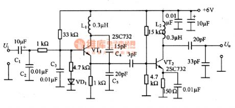
This is the 800MHZ FM circuit. The circuit changes frequencies by changing the capacitance between the poles, which is done by changing the basic bias of the oscillating transistor with the modulation signal, and the signal can be received by the receiving circuit of the radios, the transmitting range is between 50 and 100m. To get a larger frequency drift, the volumes of C4 and C5 should be small. The inductance of L1 would better be 0.3μH or so, as TV1 is easily affected by the pole capacitance and the parasitic capacitance, so the coil should be hollow, and the tightness of the wire is regulated meanwhile so that the best inductance can be got.
(View)
View full Circuit Diagram | Comments | Reading(879)
Engine Water Supply Alarm Three
Published:2011/7/29 4:37:00 Author:Felicity | Keyword: Engine Water Supply Alarm
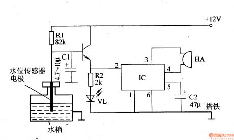
Work of the circuit
The circuit consists of water level sensor, the transistor V, resistors Rl, R2, water indication light pole tube VL, capacitors Cl, C2, integrated circuit IC and piezoelectric buzzer HA. (It is showed in picture 7-105.)
When the water level is higher than the low setting water level, VL is off and HA is noiseless
When the water level is lower than the low setting water level, the electrode of water level sensor is above water , then V is saturated and on, the high level voltage output by the emitter pole trigger VL on and also make IC at work ,then HA send out alarm.
In case of waving of the water level while driving that cause false alarm, a time delay capacitor C1 is added to the circuit . While the waving water level cause the electrode above the water instantaneously , +12 V voltage will charge C1 through R1. And because the voltage of C1 cann’t change suddenly, V cann’t be on in a sudden and there will be no false alarm. (View)
View full Circuit Diagram | Comments | Reading(1562)
Anti-theft Alarm Of Motorcycle One
Published:2011/7/29 4:44:00 Author:Felicity | Keyword: Anti-theft Alarm, Motorcycle
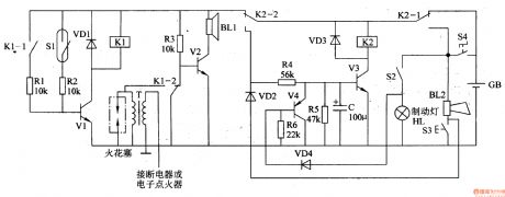
Work of the circuit
The circuit consists of trigger circuit, alarm control circuit and the reset the alarm circuit. (It is showed in picture 7-84.)
Trigger circuit consists of Mercury switches Sl, resistor cell, transistors Vl and relay Kl.
Alarm control circuit consists of the relay contacts Kl Kl-l, Kl-2, transistor V2, resistors R3 and Rl and alarm speaker BLl.
The reset the alarm circuit consists of transistors V3 and V4, the diode VD2-VD4 and relay K2.
Usually, the mercury switch S1 is off and the circuit stands by.
As soon as the theft upright the motor, the mercury switch S1 turns on to make V1 and K1 on. On one hand the normally open contact of K1-1 closes to ensure that V1 is on, on the other hand the normally close contact of K1-2 releases, and the normally open contact closes to make V2 on and BL sends out alarm, and the non-grounding terminal of the high voltage ignition coil T is connected to ground through the normally open contact of K1-2 and the motorcycle cannot start.
When the motorcycle key is plugged in and step on the brake for a while, V3 will in the on-state and the alarm will be discharged. (View)
View full Circuit Diagram | Comments | Reading(1552)
Seeder Dry Channel Blockage Alarm (the 1st)
Published:2011/8/6 8:45:00 Author:Felicity | Keyword: Seeder, Dry Channel Blockage, Alarm
Work of the circuit
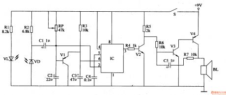
The circuit consists of infra-red detection circuit, trigger control circuit and sound alarm circuit. (It is showed in picture 4-100.)
Infra-red detection circuit consists of infrared light-emitting diode VL, infrared photodiode VD and resistors Rl, R2.
Trigger control circuit consists of transistor Vl, potentiometer RP, resistor R3, capacitor C2-C4 relative to time-base IC lC.
Sound alarm circuit consists of resistors R4-R7, transistor V2-V4, capacitor C5 and the speaker BL. (View)
View full Circuit Diagram | Comments | Reading(684)
The centralized controller of drainage and irrigation pumping station Two
Published:2011/8/8 21:43:00 Author:Felicity | Keyword: centralized controller, drainage and irrigation pumping station
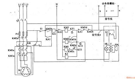
First turn Q on, and press S2 in the control room or S1 in the irrigation and drainage machine room. Then the phase voltage of L1 goes through the normally open contact of S2, signal line a, normally close contact KM2b, KM3b, KA3, KT, AKA2 to null line to make up current circuit. And KT turns on and KM1, KM2 closes in succession and the pump motor starts as Y step-down start. When it need to stop , pressing S2 or S1 again to make KA turn on, the normally open contact of KA1 close ,then the normally open contact KA2 and M3 turns off to make KM2 and KM3 release and the pump motor stops. (View)
View full Circuit Diagram | Comments | Reading(773)
The Circuit Diagram of Q-adjustable Band-stop Filter (741)
Published:2011/8/8 21:43:00 Author:Felicity | Keyword: Band-stop Filter , Q-adjustable
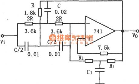
The notch frequency and the stability of Q depend on the passive components in the T-network. Appropriate components can make up a stable filter in this way. To build up a notch filter of high stability, passive components of high precision is needed besides high-performance operational amplifier. If R and C have the opposite temperature coefficient and R1, R have the same temperature coefficient, ω0 and Q are stable. (View)
View full Circuit Diagram | Comments | Reading(2078)
The circuit diagram of 8 order low-pass filter (MAX291,TA7504P)
Published:2011/8/8 21:46:00 Author:Felicity | Keyword: 8 order, low-pass filter
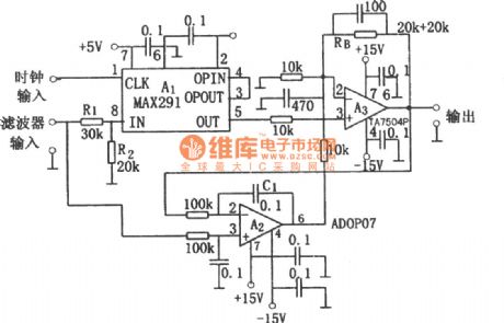
8 order low-pass filter circuit is shown in the figure. This circuit is 8 order low-pass filter circuit adopting switched-capacitor. Changing the clock frequency can change the cutoff frequency and the cutoff frequency is 1/100 of the clock frequency. +5V voltage square wave signal is put on the input terminal of the clock and then between input (IN) and output (OUT) terminal of A1 would get the performance of low-pass filter. Because of the input attenuator and the output amplifier, the input and output signal voltage can be ±10V.
(View)
View full Circuit Diagram | Comments | Reading(1506)
OPA2604 Constituted Third Order Low-pass Filter Circuit
Published:2011/8/6 8:46:00 Author:Felicity | Keyword: Third Order, Low-pass Filter
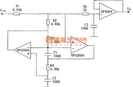
The circuit is showed in the piture above. The circuit makes use of a JFET-inputhigh-fidelityoperational amplifierOPA604 and a dualop ampOPA2604componentthird orderButterworthlow-pass filter. The parameter is showed in the picture. The cutoff frequency of-3dB is 40 KHz. (View)
View full Circuit Diagram | Comments | Reading(806)
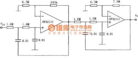
The circuit diagram of fourth-order Butterworth 10Hz low-pass filter consists of OPA2111
Published:2011/8/8 21:42:00 Author:Felicity | Keyword: fourth-order, Butterworth, low-pass filter
(View)
View full Circuit Diagram | Comments | Reading(1544)
| Pages:90/312 At 2081828384858687888990919293949596979899100Under 20 |
Circuit Categories
power supply circuit
Amplifier Circuit
Basic Circuit
LED and Light Circuit
Sensor Circuit
Signal Processing
Electrical Equipment Circuit
Control Circuit
Remote Control Circuit
A/D-D/A Converter Circuit
Audio Circuit
Measuring and Test Circuit
Communication Circuit
Computer-Related Circuit
555 Circuit
Automotive Circuit
Repairing Circuit