
Control Circuit
Index 92
Agricultural Irrigation Controller (the 1st)
Published:2011/8/6 21:05:00 Author:Felicity | Keyword: Agricultural Irrigation, Controller
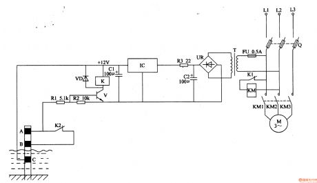
Work of the circuit
The circuit consists of power circuit and level detection control circuit. (It is showed in picture 4-91.)
Power circuit consists of fuse FU, power transformer T, bridge rectifier, UR, filter capacitors Cl, C2, limiting resistors R3 and integrated three-terminal regulator IC.
Level detection control circuit consists of high water level electrode A, the low water level electrode B, the main electrode C, resistors Rl, R2, transistor V, Relay K, diode VD and AC contactor KM.
(View)
View full Circuit Diagram | Comments | Reading(837)
The centralized controller of drainage and irrigation pumping station One
Published:2011/8/8 20:33:00 Author:Felicity | Keyword: drainage and irrigation pumping station , centralized controller,
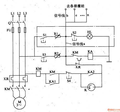
When the control room starts, the switch Q turns on. After S1 is pressed ,the phase voltage of L2 goes through S1,R1,signal line a, normally close contact of KM,KA (to null line N or ground) to make up current circuit. And KA turns on and closes, and the normally open contact KA1 switched on, the normally closed contact M2 switched off. And the phase voltage goes to phase L3 to form a circuit. After fast discharging of K, the inner contact closes to make KM turns on, and the normally open contact closes, the pump motor starting. (View)
View full Circuit Diagram | Comments | Reading(971)
Voice Cycle Lights (the 2nd)
Published:2011/8/6 21:09:00 Author:Felicity | Keyword: Voice Cycle, Lights
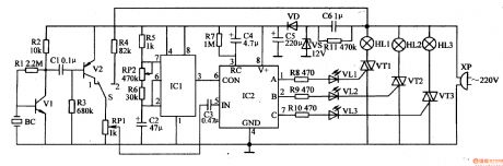
Work of the circuit
The circuit consists of power circuits, voice circuits, astable oscillator, VCO / count divider and control implementation circuit. (It is showed in picture 1-109.)
Power circuit consists of Buck capacitor C6, resistor Rll, voltage regulator diode VS, VD rectifier diode and filter capacitor C5.
Voice circuit consists of Piezoelectric ceramics BC, transistors Vl, V2, potentiometer RPl, resistors Rl-R3 and capacitor Cl, C3.
Astable oscillator consists of Time-base integrated circuit lCl and resistors R5, R6, and capacitor C2 potentiometer RP2.
VCO / count divider consists of Specific integrated circuit IC2 and lighting control resistor R7, capacitor C4.
Control implementation circuit consists of Resistor R8-RlO, VLl-VL3-emitting diode and thyristor VTl-VT3. (View)
View full Circuit Diagram | Comments | Reading(691)
Automatic Sprinkler Controller (the 2nd)
Published:2011/8/6 21:14:00 Author:Felicity | Keyword: Automatic Sprinkler, Controller
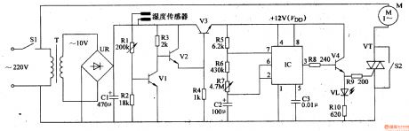
Work of the circuit
The circuit consists of power circuit, switching control circuit, astable oscillator circuit and control implementation circuit. (It is showed in picture 4-81.)
Power circuit consists of power switch Sl, the power transformer T, to bridge rectifier UR and filter capacitor Cl.
Switching control circuit consists of humidity sensors, sampling tubes Vl, composite amplifier tube V2, V3, power filtering tube and resistors Rl-R4.
Astable oscillator circuit consists of Time-base integrated circuit lC and external RC components.
Control implementation circuit consists of transistor V4, LED VL, VT, and manual control thyristor switch S2. (View)
View full Circuit Diagram | Comments | Reading(769)
Voice Cycle Lights (the 1st)
Published:2011/8/6 21:08:00 Author:Felicity | Keyword: Voice Cycle, Lights
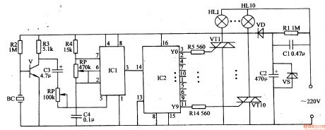
Work of the circuit
The circuit consists of power circuits, voice circuits, oscillator, pulse counting distributor and control implementation circuit. (It is showed in picture 1-108.)
Power circuits consists of buck capacitor Cl, resistors Rl, voltage regulator diode VS, filter capacitor C2 and diode rectifier VD.
Voice circuits consists of piezoelectric transducer BC, the transistor V, resistors R2, R3, capacitor C3 and potentiometer RPl.
Oscillator consists of time-base integrated circuit ICl, resistor R4, capacitor C4 and potentiometer RP2.
Pulse counting distributor consists of count / pulse distributor circuit IC2.
Control implementation circuit consists of thyristor VTl-VTlO, resistors R5-R14 and lanterns HLl-HLlO.
(View)
View full Circuit Diagram | Comments | Reading(769)
Automatic Sprinkler Controller (the 1st)
Published:2011/8/6 21:12:00 Author:Felicity | Keyword: Automatic Sprinkler Controller (the 1st)
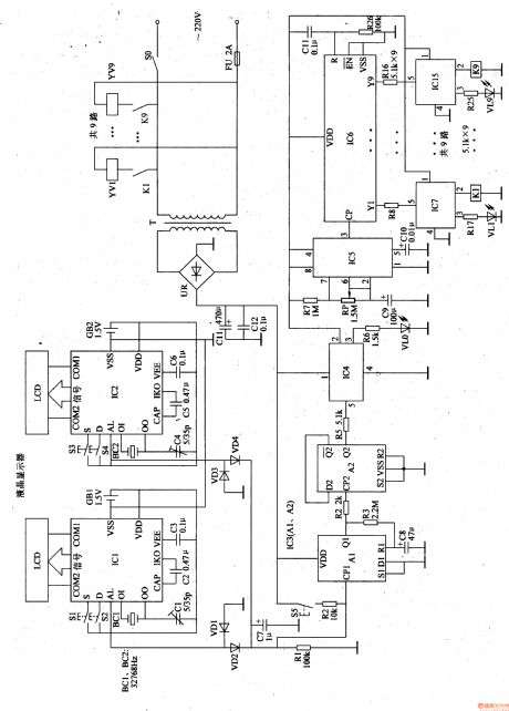
Work of the circuit
The circuit consists of clock timing controller, a single-shot, flip flop, electronic switch, self-excited multivibrator, counter, solenoid valve control circuit and power circuit. (It is showed in picture 4-80.)
Clock timing controller consists of digital electronic clock integrated circuit ICl, IC2, LCD liquid crystal displays, quartz crystal BCl, BC2, adjustable button Sl-S4, battery GBl, GB2 and capacitors Cl-C6.
Single-shot consists of dual D flip-flop within the D flip-flop integrated circuit IC3 Al and peripheral components.
Flip flop consists of D trigger A2 within IC3.
Electronic switch consists of High-power switch integrated circuit IC4.
Self-excited multivibrator consists of time-base integrated circuits IC5 and peripheral components.
Counter consists of counter / divider integrated circuit IC6 and peripheral components.
Solenoid valve control circuit consists of electronic switch integrated circuit IC7. ICI5, relay Kl-K9, LED VLl-VL9, solenoid valve YVl-YV9 and resistors R8-R25.
Power circuit consists of electronic switch integrated circuit IC7. ICI5, relay Kl-K9, LED VLl-VL9, solenoid valve YVl-YV9 and resistors R8-R25.
(View)
View full Circuit Diagram | Comments | Reading(1239)
The circuit diagram of active low-pass filter(LM102)
Published:2011/8/6 0:02:00 Author:Felicity | Keyword: active low-pass filter
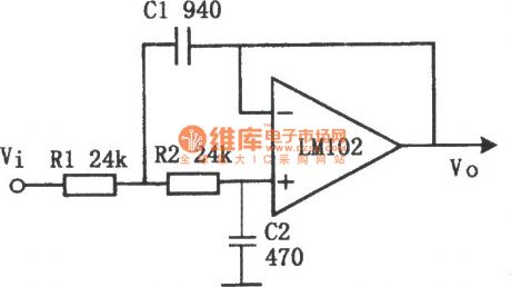
The figure shows the circuit diagram of active low-pass filter (LM102).The cutoff frequency fc=10 kHz. In the circuit, the ratio of R1 to R2 or of C1 to C2 can be any value. In this circuit, R1=R2 and C1=C2. C1=C2 and R1=R2 can also be okay. (View)
View full Circuit Diagram | Comments | Reading(1998)
Cycle timing controller 2
Published:2011/8/8 3:43:00 Author:Ecco | Keyword: Cycle timing controller
The cycle timing control circuit is composed of the power supply circuit and timing control circuit, and it is shown in Figure 3-90. Power supply circuit is composed of the fuse FU, power transformer T, bridge rectifier UR, filter capacitor C3, three-terminal voltage regulator integrated circuit IC2, current limiting resistor Rl and the power indicator LED VLl. Timing control circuit is composed of the time-base integrated circuit ICl, relay K, potentiometers RPl, RP2, resistor R2, capacitors Cl, C2, working indicating LED VL2 and diode VD. Rl and R2 use the 1/4W carbon film resistors or metal film resistors. RPl and RP2 use the small solid potentiometers or variable resistors.
(View)
View full Circuit Diagram | Comments | Reading(859)
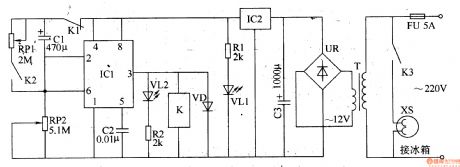
Cycle timing controller 4
Published:2011/8/8 3:27:00 Author:Ecco | Keyword: Cycle timing controller
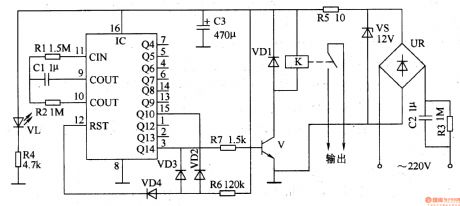
The cycle timing controller circuit is composed of the power supply circuit, timer and control implementation circuit, and it is shown in Figure 3-92. The power supply circuit is composed of the step-down capacitor C2, discharge resistor R3, bridge rectifier UR, voltage regulator diode VS, current limiting resistors R4, R5, filter capacitor C3 and power indicator light-emitting diode VL. The timer circuit consists of the counter / divider integrated circuit IC and resistors Rl, R2, R6, capacitor Cl and diodes VD2-VD4. Rl, R2, Cl and lC form the clock oscillator circuit with the oscillation signal period (T) determining by the value of R2 and Cl.
(View)
View full Circuit Diagram | Comments | Reading(1149)
Cycle timing controller 3
Published:2011/8/8 3:47:00 Author:Ecco | Keyword: Cycle timing controller

The cycle timing control circuit is composed of the power supply circuit, ultralow frequency oscillator, display driver circuit, counting flip-flop and control implementation circuit, and it is shown in Figure 3-91. The power supply circuit consists of the step-down capacitor C6, discharge resistor Rl5, rectifier diode VDl, voltage regulator diode VS and filter capacitor C5. Ultralow frequency oscillator consists of the dual D flip-flop IC IC2 (a D flip-flop which is inside of IC2) and electronic switch circuit ICl, potentiometers RPl, RP2, resistors Rl, R2, capacitors Cl, C2, diodes VD3, VD4.
(View)
View full Circuit Diagram | Comments | Reading(1385)
Over-temperature monitoring automatic control circuit diagram
Published:2011/8/4 21:54:00 Author:Rebekka | Keyword: Over-temperature monitoring , automatic control
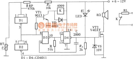
The circuit is composed of a NAND gate circuit, a thermistor composition measurement, control circuit and sirens generating circuit. It uses a relay as the implementation circuit. Its structure is simple and easy to make, economical and practical. The constitution of the circuit is shown as above. (View)
View full Circuit Diagram | Comments | Reading(1318)
Electronic refrigerator temperature controller circuit diagram
Published:2011/8/4 21:53:00 Author:Rebekka | Keyword: temperature controller, Electronic refrigerator

Since the point A of this circuit sensor VD2 negative end potential design is 1 0 ℃, and V head is 0 V and it shows 00.0 , so the circuit uses3kΩ RP3. The pin 30 of theintegrated circuit 7170 is connected to the ground (shown in play x place). It makes the potential Vin of the head increase 1V. When commissioning VD2 sensor is in the ice water mixture, the potentiometer RP3 makes the head show 00.0 . Put the VD2 in boiling water, and the RP4 potentiometer makes the head show 100.0 , the debugging is brought to an end. (View)
View full Circuit Diagram | Comments | Reading(1975)
Electric blanket temperature controller circuit composed of Y982 module
Published:2011/8/4 21:49:00 Author:Rebekka | Keyword: Electric blanket, temperature controller
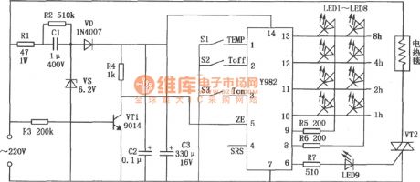
Y982 power adjustment module can be used for a variety of electric heater control. It can be used for the adjustment of the size of used appliances power. It has a timer function. It is an ideal transfer function devices. Electric blanket temperature controller circuit composed of Y982 module is shown as above. (View)
View full Circuit Diagram | Comments | Reading(3282)
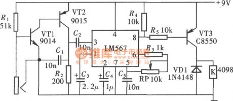
Frequency type electronic coded lock (LM567) circuit
Published:2011/7/20 20:39:00 Author:Fiona | Keyword: Frequency type, electronic coded lock
View full Circuit Diagram | Comments | Reading(2812)
Touch switch (CD4069) circuit composed of gate circuit
Published:2011/7/20 20:53:00 Author:Fiona | Keyword: Touch switch, gate circuit
View full Circuit Diagram | Comments | Reading(926)
Temperature-frequency conversion temperature controller circuit composed of NE555 and LM567
Published:2011/8/4 21:26:00 Author:Rebekka | Keyword: Temperature- frequency conversion, temperature controller

View full Circuit Diagram | Comments | Reading(2515)
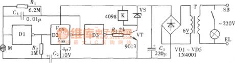
Light touching light control delay energy-saving switch circuit
Published:2011/7/20 21:26:00 Author:Fiona | Keyword: Light touching, light control, delay, energy-saving
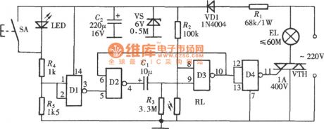
View full Circuit Diagram | Comments | Reading(941)
Touching voice control lamp switch circuit
Published:2011/7/20 23:01:00 Author:Fiona | Keyword: Touching, voice control, lamp switch
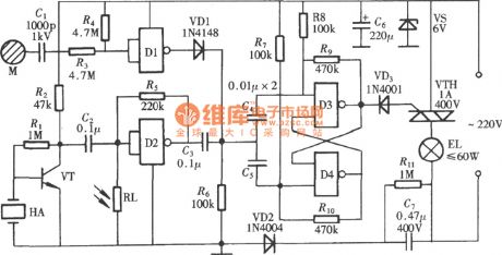
View full Circuit Diagram | Comments | Reading(1465)
Op amp output short circuit protection method circuit diagram
Published:2011/8/4 21:01:00 Author:Rebekka | Keyword: Op amp, output short circuit, protection method
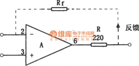
The protection method of the op amp's output short circuit is simple. It only needs to connect a small resistor R in series at the op amp output, the output short-circuit failure can be avoided. It is shown as above. If the resistor is connected to the internal feedback loop, it will have no influence on any performance but the voltage will decrease obviously(When the load is 2kΩ, the value is shown in the figure, Vo can be decreased by 10%). Another advantage of this circuit is: The circuit is also very stable for the external capacitive load. Even if the integrated operational amplifier has been added within the current limiting resistor, a small resistor should also be added at the external op amp output end. (View)
View full Circuit Diagram | Comments | Reading(3019)
Reflection loss bridge type circuit used to measure impedance matching
Published:2011/8/7 4:58:00 Author:Sophia | Keyword: Reflection loss bridge type circuit, measure impedance matching
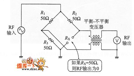
In the high-frequency circuits, impedance matching is the key. If the problems of impedance mismatch and signal reflection appear, which will produce a standing wave to cause the abnormal condition of the signal transmission .
For example, in a 50Ω transmission line, if you connect a 50Ω load impedance, then all power is supplied to the load. Of course, it is the normal state when reflection power is 0.
When mismatch state is showed, the reflection coefficient, standing wave ratio (VSWR: Volt-age Standing Wave Ratio) and mismatch losses (ie reflection loss) and other terms can be used. (View)
View full Circuit Diagram | Comments | Reading(1274)
| Pages:92/312 At 2081828384858687888990919293949596979899100Under 20 |
Circuit Categories
power supply circuit
Amplifier Circuit
Basic Circuit
LED and Light Circuit
Sensor Circuit
Signal Processing
Electrical Equipment Circuit
Control Circuit
Remote Control Circuit
A/D-D/A Converter Circuit
Audio Circuit
Measuring and Test Circuit
Communication Circuit
Computer-Related Circuit
555 Circuit
Automotive Circuit
Repairing Circuit