
Control Circuit
Index 84
Multi-function timer controller 1
Published:2011/8/8 21:27:00 Author:Ecco | Keyword: Multi-function timer controller
The multi-function timing controller circuit is composed of the power supply circuit, clock signal generator, counting distributor, RS flip-flop and switch output circuit, and it is shown in Figure 3-94. Power supply circuit consists of the power transformer T, rectifier diodes VD3-VD6, filter capacitors Cl, C5, current limiting resistor R5 and Zener diode VS. Clock signal generator consists of the electronic watch, diode VDl, capacitor C2 and counter / divider integrated circuit lCl. Count divider circuit consists of the counter / divider integrated circuit IC2, resistors Rl, R2, timer selection switches Sl, S2 and reset button S4.
(View)
View full Circuit Diagram | Comments | Reading(839)
Multi-function timer controller 2
Published:2011/8/8 21:33:00 Author:Ecco | Keyword: Multi-function timer controller
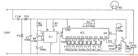
The multi-function timing controller circuit is composed of the power supply circuit, pulse generator, delay control circuit and control implementation circuit, and it is shown in Figure 3-95. The power supply circuit consists of the step-down capacitor Cl, voltage regulator diode VS, rectifier diode VDl and filter capacitor C2. The pulse generator consists of the time-base ICl, resistors Rl, R2, potentiometer RP and capacitor C3. Delay control circuit consists of the decimal counting / pulse distributor circuit IC2, resistors R3, R4, diodes VD2-VD11, switches S1-S12. Control implementation circuit consists of transistor V, resistors R5, R6 and thyristor VT.
(View)
View full Circuit Diagram | Comments | Reading(1654)
Drilling security controller circuit diagram
Published:2011/8/21 21:50:00 Author:Ecco | Keyword: Drilling security controller
The drilling security controller is composed of the trigger switches S1 ~ Sn, resistors R1 and R2, potentiometer RP, capacitors C1 ~ C3, LEDs VL1 and VL2, diodes VD1 and VD2, time-base integrated circuit IC and the relay K, amd it is shown as the chart. R1 and R2 select the 1/4W metal film resistors. RP uses the organic solid carbon resistor or potentiometer. C1 and C3 select the electrolytic capacitors with voltage in 16V; C2 uses the monolithic capacitor or polyester capacitor. VD1 and VD2 use the 1N4007 silicon rectifier diodes. VL1 and VL2 select the φ5mm LEDs, VL1 chooses green, and VL2 chooses red.
(View)
View full Circuit Diagram | Comments | Reading(747)
Industrial X-ray diagnostic machine delay control switch circuit diagram
Published:2011/8/22 2:51:00 Author:Ecco | Keyword: Industrial, X-ray diagnostic machine, delay control switch
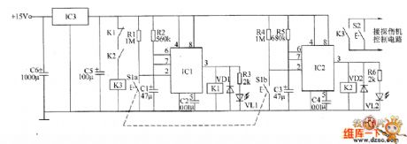
The industrial X-ray diagnostic machine delay control switch circuit is composed of the regulator filter circuit, delay control circuit A, delay control circuit B and control implementation circuit, and it is shown as the chart. Regulator filter circuit is composed of the capacitors C5, C6 and three-terminal voltage regulator integrated circuit IC3. The delay control circuit A is composed of the resistors R1 ~ R3, capacitors C1, C2, time-base integrated circuit IC1, diode VD1, relay K1, LED VL1, control button Sla. Control implementation circuit is composed of the normally closed contacts of the relay K3 and K1, the normally open contacts of K2, high button S2. (View)
View full Circuit Diagram | Comments | Reading(2124)
Up / down machine motor overruning brake controller circuit diagram
Published:2011/8/22 2:57:00 Author:Ecco | Keyword: Up / down machine motor , overruning brake controller
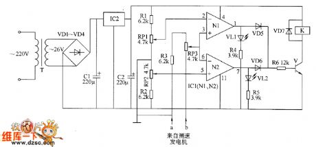
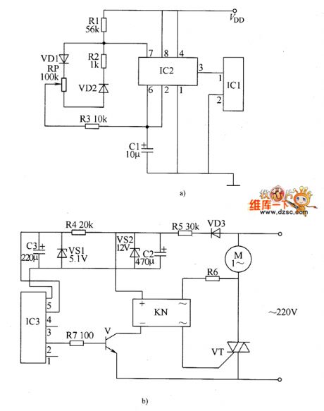
The up / down machine motor overruning brake controller circuit is composed of the power supply circuit, LED indication circuit and speed control circuit, and it is shown as the chart. Power supply circuit is composed of the power transformer T, rectifier diodes VD1 ~ VD4, filter capacitors C1, L2, and three-terminal voltage regulator integrated circuit IC2. LED indicator circuit is composed of the light-emitting diodes VL1, VL2, and resistors R4, R5. Speed control circuit is composed of the resistors R1 ~ R6, potentiometers RP1, RP2, operational amplifier integrated circuit IC1 (M, N2), diodes VD5 ~ VD7, transistor V, and relay K.
(View)
View full Circuit Diagram | Comments | Reading(1235)
Motor electronic speed controller circuit diagram 7
Published:2011/8/21 21:42:00 Author:Ecco | Keyword: Motor , electronic speed controller
The electronic motor speed controller circuit consists of wireless remote control transmitter circuit, wireless remote control receiver control circuit, and it is shown as the chart. Wireless remote control transmitter circuit is composed of the micro-power wireless remote control transmitter IC module IC1, time-base integrated circuit IC2, diodes vD1, VD2, resistors R1 ~ R3, potentiometer wireless remote control receiver control circuit is composed of the micro-power wireless remote control receiver IC module IC3, voltage regulator diodes VS1, VS2, resistors M ~ R7, diode VD3, transistor V, solid state relays KN (SSR) and thyristor VT.
(View)
View full Circuit Diagram | Comments | Reading(4186)
Punch security controller circuit diagram 4
Published:2011/8/21 22:00:00 Author:Ecco | Keyword: Punch security controller
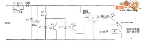
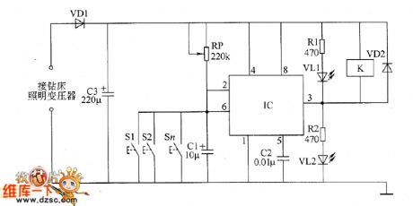
The punch security controller circuit is composed of the DC power supply circuit, infrared detection control circuit and control implementation circuit, and it is shown as the chart. DC power supply circuit consists of step-down capacitor C1, discharge resistor R1, rectifier diode VD1, voltage regulator diode VS and filter capacitor C2. Infrared detection control circuit is composed of the infrared light emitting diodes VL1 and VL2, infrared phototransistors V1 and V2, resistor R2, potentiometer RP and voltage detection circuit IC. Control implementation circuit is composed of the resistor R3, transistor V3, diode VD2, relay Κand foot switch S.
(View)
View full Circuit Diagram | Comments | Reading(716)
Atmospheric pressure boiler automatic temperature controller circuit diagram
Published:2011/8/21 22:09:00 Author:Ecco | Keyword: Atmospheric pressure boiler, automatic temperature controller
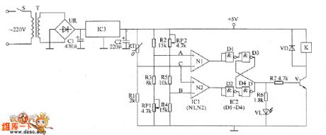
The atmospheric pressure boiler automatic temperature controller circuit is composed of the power supply circuit, temperature detection control circuit, trigger, work status indication circuit and control implementation circuit, and it is shown as the chart. Temperature detection control circuit is composed of the temperature sensor RT, resistors R1 ~ R5, potentiometers RP1, RP2, and operational amplifier integrated circuit IC1 (N1, N2). Trigger consists of four NAND gate IC IC2 internal NAND gates D1 ~ D4. Control implementation circuit is composed of the resistor R7, transistor V, diode VD and relay K. Working status indication circuit consists of current limiting resistor R6 and light-emitting diode VL.
(View)
View full Circuit Diagram | Comments | Reading(2401)
Industrial fuel oil furnace controller circuit diagram 2
Published:2011/8/21 21:38:00 Author:Ecco | Keyword: Industrial , fuel oil furnace , controller
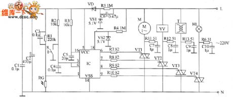
The industrial fuel oil furnace controller circuit is composed of the power supply circuit, testing and ignition control circuit and control implementation circuit, and it is shown as the chart. The power supply circuit is composed of the step-down capacitor C6, discharge resistor R5, voltage regulator diode VS1, rectifier diode VD and filter capacitors C1, C2. Testing and ignition control circuit consists of resistors R1 ~ M, photoresistor RC, capacitors C3 ~ C5, reset button S, voltage regulator diode VS2 and control IC. R2, S, and C4 form the reset circuit; R1, C3 and the RC form the photoelectric detection circuit; R4 and VS2 form the zero-crossing detection circuit.
(View)
View full Circuit Diagram | Comments | Reading(3051)
Three-phase permanent magnet brushless DC motor MC33035 control system circuit diagram
Published:2011/8/22 3:01:00 Author:Ecco | Keyword: Three-phase, permanent magnet , brushless DC motor , control system
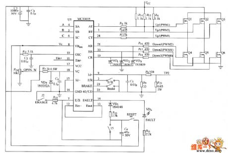
View full Circuit Diagram | Comments | Reading(12400)
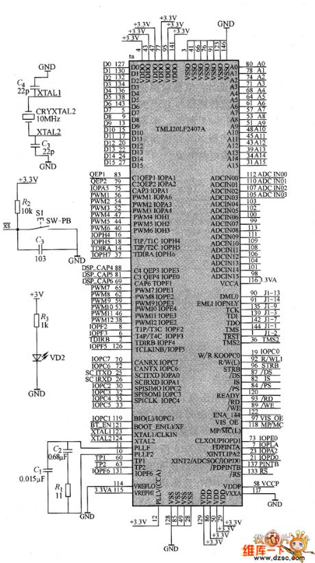
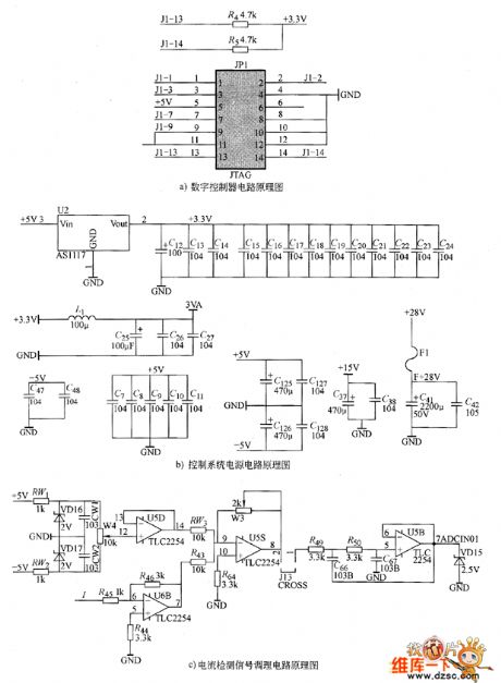
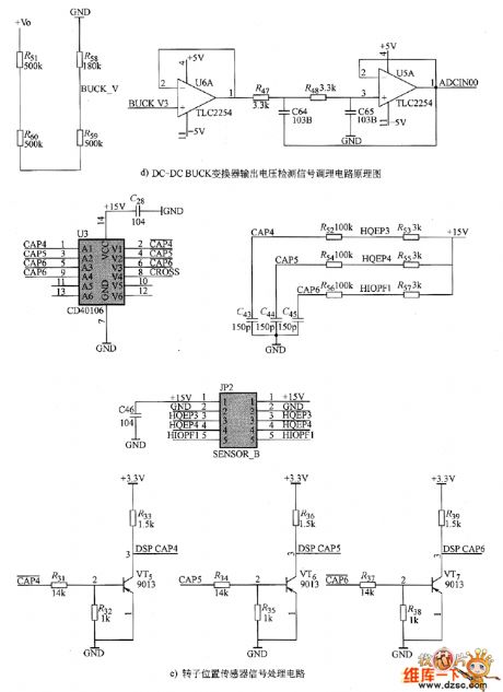
Permanent magnet brushless DC motor control circuit diagram
Published:2011/8/22 2:43:00 Author:Ecco | Keyword: Permanent magnet , brushless DC motor , control circuit
View full Circuit Diagram | Comments | Reading(1812)
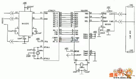
SJA1000 CAN controller application circuit diagram
Published:2011/8/25 1:03:00 Author:Ecco | Keyword: CAN controller application
View full Circuit Diagram | Comments | Reading(4308)
dual five-gear electronic switch controller circuit with CD4015,NE555
Published:2011/8/25 20:16:00 Author:chopper | Keyword: dual five-gear, electronic, switch controller
View full Circuit Diagram | Comments | Reading(6528)
Eight groups electronic responser circuit with CD4043,LM386
Published:2011/8/25 20:16:00 Author:chopper | Keyword: Eight groups, electronic responser
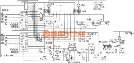
The eight groups electronic responser circuit can be used by 8 participants,and it is of functions like interlock and sound and light indication,which is shown as picture. Circuit consists of button input of eight groups and interlock circuit, sound and light indication circuit, reset circuit and the power supply circuit. (View)
View full Circuit Diagram | Comments | Reading(1886)
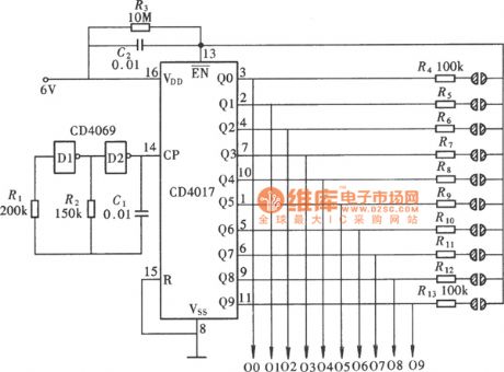
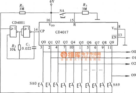
Ten-gear interlock switch controller circuit with CD4017,CD4001
Published:2011/8/25 20:12:00 Author:chopper | Keyword: Ten-gear, interlock switch, controller circuit
View full Circuit Diagram | Comments | Reading(3546)
Home theater system power control switch CD4013,CD4017 circuit
Published:2011/8/25 20:13:00 Author:chopper | Keyword: Home theater, power, control switch
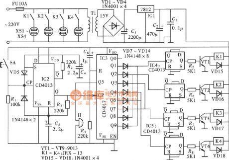
View full Circuit Diagram | Comments | Reading(5040)
SST8803,UM3758-108A data transmission modulation and demodulator circuit
Published:2011/8/25 20:21:00 Author:chopper | Keyword: data transmission, modulation, demodulator
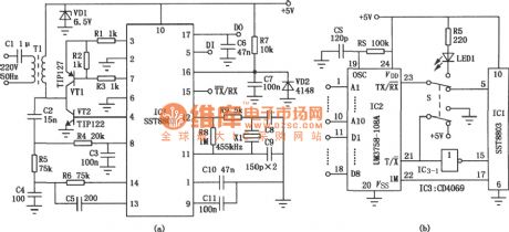
The main components IC1 of the circuit is the modulation/demodulation IC SST8803 of new grid carrier digital pulse signal transmission,it has low power consumption, high sensitivity, good anti-jamming and good anti-static performance,and the single chip can complete all the work including the data signal modulation,send and receive, demodulation. It can use low-voltage power lines, broadcast cable and closed television signal lines as carriers for data exchange of information, can also be used for some systems like remote telemetry, centralized alarm,multi-channel paging and microcomputer network.
(View)
View full Circuit Diagram | Comments | Reading(2353)
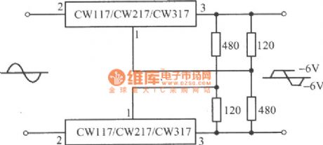
CW117,CW217,CW317 Ac peak clip circuit
Published:2011/8/25 20:22:00 Author:chopper | Keyword: Ac peak, clip circuit
View full Circuit Diagram | Comments | Reading(954)
LM111,211,311 single voltage comparator
Published:2011/8/25 20:22:00 Author:chopper | Keyword: single voltage, comparator
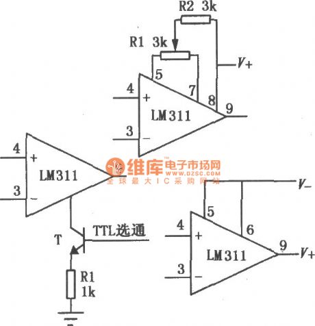
The power supply voltage range of LM111/211/311 is big(± 5V~± l5V), bias current is small, offset current is small, and differential input voltage range is big(± 30V),and its output is compatible with TTL, DTL and MOS circuit , and it can drive the indicator light and relay. It adopts either single power supply or dual power supply, and has two forms of collector output and emitter output . This comparator also has the external balance adjustment end and the gate control side, and it can be selected or adjusted when it is in usage. The basic circuit is shown as picture.
(View)
View full Circuit Diagram | Comments | Reading(1183)
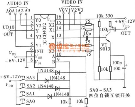
four-channel A/V convertion circuit(CD4052)
Published:2011/7/24 2:36:00 Author:chopper | Keyword: four-channel, A/V, convertion circuit
View full Circuit Diagram | Comments | Reading(11551)
| Pages:84/312 At 2081828384858687888990919293949596979899100Under 20 |
Circuit Categories
power supply circuit
Amplifier Circuit
Basic Circuit
LED and Light Circuit
Sensor Circuit
Signal Processing
Electrical Equipment Circuit
Control Circuit
Remote Control Circuit
A/D-D/A Converter Circuit
Audio Circuit
Measuring and Test Circuit
Communication Circuit
Computer-Related Circuit
555 Circuit
Automotive Circuit
Repairing Circuit