
Control Circuit
Index 98
DIATHERMY_FREQUENCY_MONITOR_AND_CONTROL
Published:2009/7/14 3:40:00 Author:May
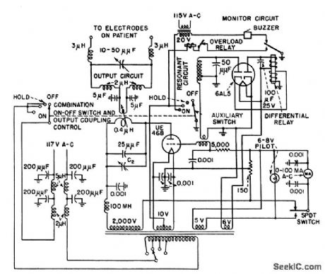
Monitor circuit stops 27.12-Mc oscillator and sounds buzzer when frequency drifts beyond legal limits established by FCC.-J. Markus and V. Zeluff, Handbook of Industrial Electronic Control Circuits, McGraw-Hill, N.Y., 1956, p 100. (View)
View full Circuit Diagram | Comments | Reading(942)
PULSER_AND_KEYER
Published:2009/7/14 3:34:00 Author:May
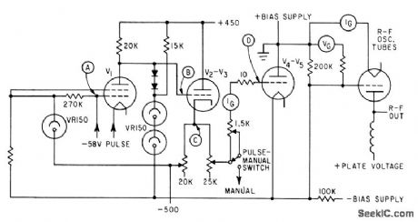
Used to control power oscillator of induction heater at rates up to 800 pps.-R. E. Mathews and F. R. Mathews and F.R.Sias, Jr., Testing Space Craft with Induction Heaters, Electronics, 35:34, p 38-41. (View)
View full Circuit Diagram | Comments | Reading(778)
_10_V_SWITCHING
Published:2009/7/14 3:34:00 Author:May
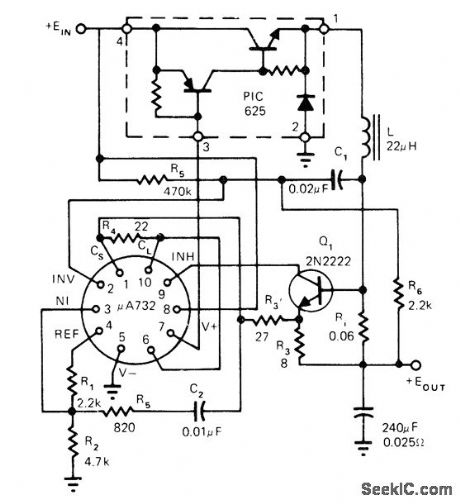
Positive switching regulator circuit uses, μA732 with Unitrode PIC625 hybrid power switch and single transistor, operating in fixed OFF-time mode. Article covers regulator theory of operation in detail.-L. Dixon and ft. Patel, Designers' Guide to: Switching Regulators, EDN Magazine, Oct, 20, 1974, p 53-59. (View)
View full Circuit Diagram | Comments | Reading(830)
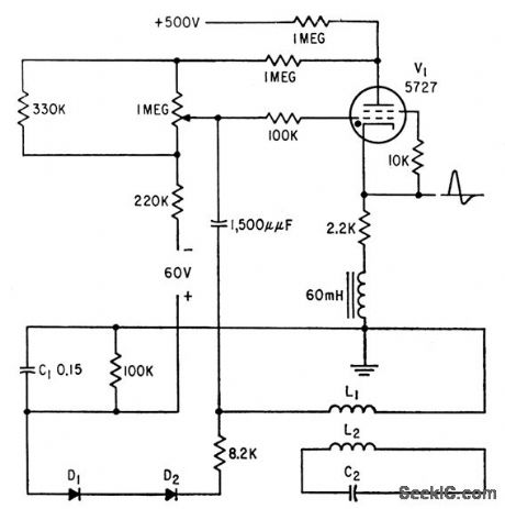
INDUCTION_HEATER_CONTROL
Published:2009/7/14 3:34:00 Author:May
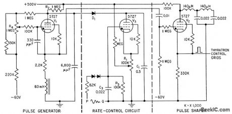
Thyratron n pulse generator V1 produces voltage pulses of adjustable frequency for pulse shaper V2, which drives hydrogen thyatrons of high-power induction heater. V3 regulates repetition rate of pulses by acting as switch that, when conducting, allows C1 to discharge rapidly through R1.-H. L. Van Der Horst, How Radar Techniques Improve Induction Heating, Electronics, 32:7, P 51-55. (View)
View full Circuit Diagram | Comments | Reading(2743)
REFERENCE_SWITCH
Published:2009/7/14 3:32:00 Author:May
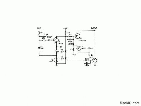

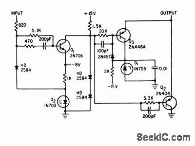
Provides low-zero-offset 5-microsec pulses with stabilized amplitude, obtained from synchronous flip-flop. Output pulses switch from zero to -5 v, for driving compute and hold amplifiers of serial decoder,-R. M.Centner and J. R. Wilkinson, New Approach to Serial Decoding Eliminates Static Storage, Electronics, 35:34, p 32-35. (View)
View full Circuit Diagram | Comments | Reading(903)
5_V_TO_200_V_WITH_SWITCHING_REGULATOR
Published:2009/7/14 3:31:00 Author:May
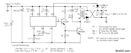
Converts standard logic supply voltage to high voltage required by gas-discharge displays, sing Motorola MC3380 as table MVBR as control element in switching regulator. Will drive up to 15 digits. Operating frequency is about 20 kHz.-H. Wurzburg, Control Your Switching Regulator with the MC3380 As table Multivibrator, Motorola, Phoenix, AZ, 1975, EB-52. (View)
View full Circuit Diagram | Comments | Reading(799)
REPETITION_RATE_CONTROL
Published:2009/7/14 3:31:00 Author:May
Compensates for fluctuations in repetition rate of hydrogen thyratron in induction heater. Ripple voltage induced in L1 acts on control grid of V1 to displace peaks at which ignition occurs in correct direction to maintain constant repetition rate in damped circuit.-H. L. Van Der Horst, How Radar Techniques Improve Induction Heating, Electronics, 32:7, p 51-55. (View)
View full Circuit Diagram | Comments | Reading(659)
REDUCING_24_V_TO_5_V
Published:2009/7/14 3:29:00 Author:May
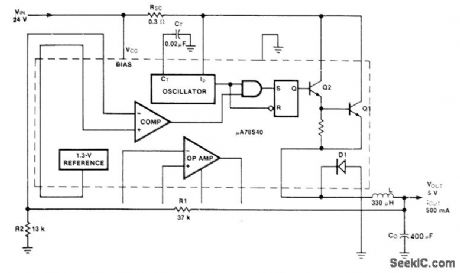
Uses Fairchild μA78S40 switching regulator having variety of internal functions that can provide differing voltage step-up, step-down, and inverter modes by appropriately connecting external components. Connections shown provide step-down from 24 V to 5 V at 500 mA with 83% efficiency. Applications include running TTL from 24-V battery. Output ripple is less than 25 V. Article gives design equations.-R. J. Apfel and D. B. Jones, Universal Switching Regulator Di-versifies Power Subsystem Applications, Computer Design, March 1978, p 103-112. (View)
View full Circuit Diagram | Comments | Reading(783)
_5_V_AT_3_A_SWITCHING
Published:2009/7/14 3:27:00 Author:May
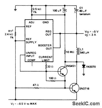
Negative-voltage regulator using SN52104 or SN72304 accepts input voltage range of -8.5 V to -40 V and pro-vides regulated output of -5 V with typical load regulation of 1 mV and input regulation of 0,06%. ICs are interchangeable with LM104 and LM304 respectively. L1 is 60 turns No. 20 on Arnold Engineering A930157-2 molybdenum permalloy core or equivalent.- The Linear and Interface Circuits Data Book for Design Engineers, Texas Instruments, Dallas, TX, 1973, p 5-5. (View)
View full Circuit Diagram | Comments | Reading(892)
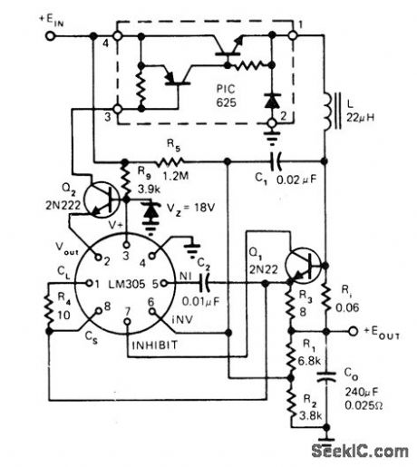
HIGH_VOLTAGE_POSITIVE_SWITCHING
Published:2009/7/14 3:24:00 Author:May
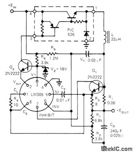
Uses 18-V zener in series with 3.9K resistor to provide power for LM305 IC regulator. Q2 provides base drive for PIC626 hybrid power switch and isolates output of LM305 from switch.-L. Dixon and R. Patel, Designers' Guide to: Switching Regulators, EDN Magazine, Oct. 20, 1974, p 53-59. (View)
View full Circuit Diagram | Comments | Reading(986)
_5_V_FLYBACK_SWITCHING
Published:2009/7/14 3:18:00 Author:May

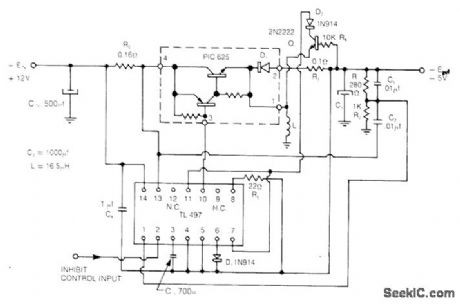
Uses Unitrode PIC625 regulator operating at 25 kHz and TL497 control circuit operating in current-limiting mode to give line and load regulation of 0.2% for input voltage of 12 V ±25%. Efficiency is 75%. Short-circuit current is automatically limited to 3 A.- Flyback and Boost Switching Regulator Design Guide, Unitrode, Watertown, MA, 1978, U-76, p 5. (View)
View full Circuit Diagram | Comments | Reading(2654)
VARIABLE_SWITCHING_FREQUENCY
Published:2009/7/14 3:12:00 Author:May

TL497 switching regulator operates at maximum frequency under maximum load conditions. For smaller loads, duty cycle is varied automatically by maintaining fixed ON time and varying switching frequency. Circuit optimizes efficiency at about 75% by reducing switching losses as load decreases.-J. Spencer, Monolithic Switching Regulators-They Fit Today's Power-Supply Needs, EDN Magazine, Sept. 5, 1977, p 117-121. (View)
View full Circuit Diagram | Comments | Reading(1958)
5_V_40_A_20_kHz_SWITCHED_MODE
Published:2009/7/14 3:11:00 Author:May
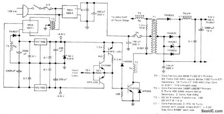
Uses Motorola 2N6544 power transistors operating with 3-A collector current (other half of power stage is identical). Bridge rectifier and capacitive filter connected directly to AC line form 150-VDC sup-ply for inverter operating at 20 kHz. Regulators MC7806 and MC7906 operating from MDA9221 bridge rectifier of 15-W filament transformer T3 provide ±6 V for logic circuits that provide pulse-width modulation for inverter. When logic signal is high, MPS-U51 saturates and supplies 1 A to base of 2N6544 inverter power transistor When logic is low, MPS-U95 Darlington holds inverter transistor off.-R. J. Haver, Switched Mode Power Supplies-Highlighting a 5-V, 40-A Inverter Design, Motorola, Phoenix, AZ, 1977, AN-737A, p 10. (View)
View full Circuit Diagram | Comments | Reading(1503)
5_V_FIXED_OFF_TIME_SWITCHING
Published:2009/7/14 2:53:00 Author:May
Uses LM305 regulator and Unitrode hybrid power switch in PIC600 series. Operates in fixed OFF-time mode. Output ripple of 100 mV P-P is independent of input voltage range of 20 to 40 V for output of +5 V ±1%. Switching speed is nominally 50 kHz but can go up to 100 kHz. Article covers theory of operation in detail.-L. Dixon and R. Patel, Designers' Guide to: Switching Regulators, EDN Magazine, Oct. 20, 1974, p 53-59. (View)
View full Circuit Diagram | Comments | Reading(773)
_5_V_SWITCHING_AT_10_A
Published:2009/7/14 2:52:00 Author:May
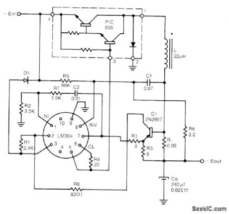
Uses Unitrode PIC635 hybrid power switch with LM304 regulator for switching speeds up to 100 kHz with input voltage range of 20-40 V. 01 provides cur-rent-limiting action.- Switching Regulator Design Guide, Unitrode, Watertown, MA, 1974, U-68A, p 9. (View)
View full Circuit Diagram | Comments | Reading(0)
TRANSFORMER_WINDING_SPEEDS_SWITCHING
Published:2009/7/15 5:13:00 Author:Jessie
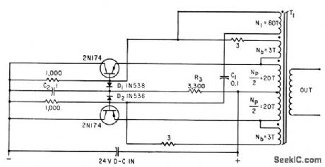
Addition of speed-up winding N1 to con ventional transformer orrangement of inverler, with C1 in series with N1, increases switching speed. Clipping of resulting base-collector voltage spikes is provided by net work D1-D2-C2-R3.-A. G. Lloyd, Speed4Jp Circuits Improve Switching of Transistor Inverters, Electronics, 34:45, p 92-94. (View)
View full Circuit Diagram | Comments | Reading(810)
ALIERNATOR_FREQUENCY_CONTROL
Published:2009/7/15 21:02:00 Author:Jessie

Servo discriminator measures phase with respect to preadjusted components, making accuracya function of initial setting. At 400 cps, d-c output is l00 mV for frequency deviation of 0.5 cps. Absolute accuracy is 0.125% between -55 and +100℃ ambient. Used as error-sensing device with servo drive in feedback control loop of constant-speed transmission for aircraft alternators.-R. Hill, Discriminator Controls Aircraft Alternator, Electronics, 31:41, p 94-95. (View)
View full Circuit Diagram | Comments | Reading(745)
5_24_V_SWITCHING
Published:2009/7/14 2:49:00 Author:May

Choice of regulator in μA7800 series determines fixed output voltage. Devices are available for rated outputs of 5, 6, 8, 12, 15, 18, and 24 V, positive or negative, with output current ratings of 100 mA, 500 mA, or 1 A. If input voltage is greater than maximum input rating of regulator used, add voltage-dropping zener Dl to bring voltage between pins 1 and 3 down to acceptable level.- Signetics Analog Data Manual, Signetics, Sunnyvale, CA, 1977, p 668, (View)
View full Circuit Diagram | Comments | Reading(875)
CAMCORDER_BATTERY_PROTECTOR
Published:2009/7/14 2:27:00 Author:May
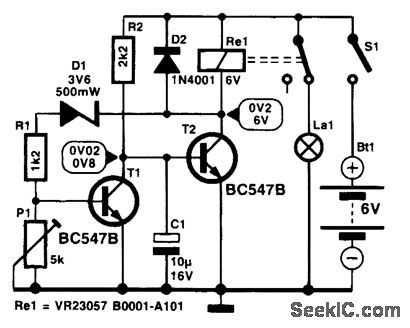
Many camcorder enthusiasts use their spare battery for powering video lights. Many such lights give no indication when the battery has gone flat. This can be avoided by the use of this protection circuit. When it gets switched on, the potential across C1 is zero, so that T2 is cut off, the relay is inactive, and the indicator lamp lights. As long as the battery voltage remains above a certain level, T1 is on and holds the base of T2 at earth potential. In this state, only a small current is drawn. When the battery voltage is no longer higher than the sum of the zener voltage, the potential set by divider R2-P1, and the drop across the base-emitter junction of T1, this transistor is cut off, whereupon C 1 is charged via R2. When the potential across C1 has risen to a value high enough for T2 to be switched on, the relay is energized, and its contact disconnects the lamp from the battery. Because the current drain (≤70 rnA) is then determined almost entirely by the relay, it is essential to remove, or disconnect, the battery from the light unit. The switch-off voltage level, set with P1, should be about 1 V per battery cell. (View)
View full Circuit Diagram | Comments | Reading(849)
PULSE_COINCIDENCE_CONTROL
Published:2009/7/15 21:24:00 Author:Jessie
Coincidence of incoming code with reference pulse causes cold-cathode code tubes to fire in accordance with binary number present, for driving display panel containing eight sections each having 30 miniature fucrescent lamps.-T. S. Pick and A. Roadman, Photoelectric Scanners Control Bus traffic, Electronics, 32:28, p 50-,51. (View)
View full Circuit Diagram | Comments | Reading(809)
| Pages:98/312 At 2081828384858687888990919293949596979899100Under 20 |
Circuit Categories
power supply circuit
Amplifier Circuit
Basic Circuit
LED and Light Circuit
Sensor Circuit
Signal Processing
Electrical Equipment Circuit
Control Circuit
Remote Control Circuit
A/D-D/A Converter Circuit
Audio Circuit
Measuring and Test Circuit
Communication Circuit
Computer-Related Circuit
555 Circuit
Automotive Circuit
Repairing Circuit