
Circuit Diagram
Index 1585
Three-phase motor automatic limiting reversing circuit
Published:2011/7/9 7:47:00 Author:Lucas | Keyword: Three-phase motor, automatic limiting , reversing circuit
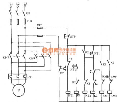
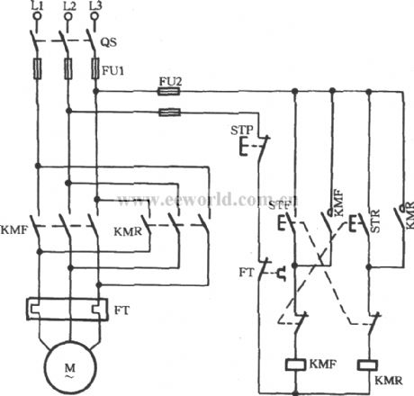
In the circuit shown as the chart, KT1, KT2 are the time relays. After closing the main switch QS, K1 and KMF pulls in, then the motor runs forward, and KT1 starts to time. When the time of KT1 arrives, it automatically disconnects, and K1 coil loses power, and KMF releases, then the motor stops; At the same time, the normally open contacts of KT1 are closed, and coil K2 pulls in, KMR coil gets electric to make motor run reversely, then KT2 starts to time. When the time of KT2 arrives, its normally contact KT2 is closed, and K2 coil loses power to make KMR release, then the motor stops. K2's loss of power could make its the normally closed contact restore normally closed state, then KT1, K1 work make the motor run forward.
(View)
View full Circuit Diagram | Comments | Reading(3626)
Three-phase motor for single-line remote commutation circuit
Published:2011/7/10 0:11:00 Author:Lucas | Keyword: Three-phase motor, single-line remote commutation
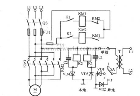
In some cases, it is needed to control motor’s starting-stopping and switching operation far away from the motor. The circuit designed for meeting this requirement is shown in the figure. Set up a wire (single wire) just as shown in the figure and select the “remote control selector switch SA. When the SA is at the position 1 , the local motor stops working. When the SA is at the position 2 , the local relay K1 creates the loop by passing through VD3, ground, VD1, SA and transformer T. When the K1 takes action, its contact connects to coil circuit of the AC contactor. And the motor transfers to run forward.
(View)
View full Circuit Diagram | Comments | Reading(3670)
Three-phase motor with a relay for inverting circuit
Published:2011/7/9 23:59:00 Author:Lucas | Keyword: Three-phase motor, relay
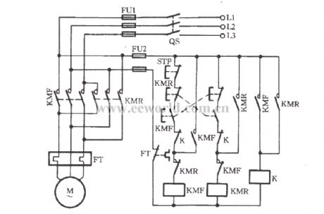
K relay is used to extend switching time for forward and reverse steering. As a result, it can avoid simultaneous suction of KMF and KMR on the reverse run. It also increases the chain reliability between the contactor and the button.
(View)
View full Circuit Diagram | Comments | Reading(1355)
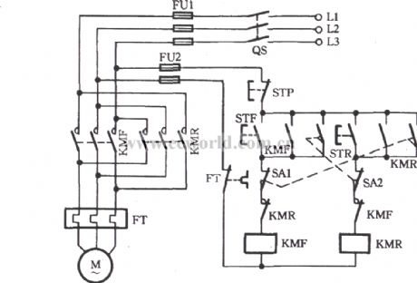
Three-phase motor using limit switch for automatically stopping inverting circuit
Published:2011/7/9 23:50:00 Author:Lucas | Keyword: Three-phase motor, limit switch
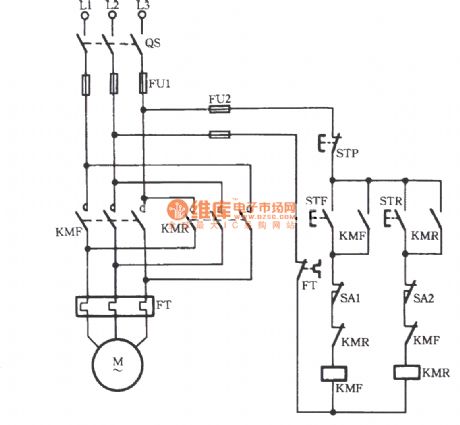
As shown in the figure, limit switches SA1 and SA2 are used to achieve the control for automatically stopping the forward and reverse running. When the mechanical impact block is driven by the motor to hit the SA1 or SA2, it means that it is equivalent to have pressed the stop button. Then the contactor KMF or KMR lose power to stop the motor.
(View)
View full Circuit Diagram | Comments | Reading(12072)
Three-phase motor using the limit switch for inverting circuit
Published:2011/7/9 23:27:00 Author:Lucas | Keyword: Three-phase motor, limit switch
As shown in the figure, two limit switches SA1 and SA2 are used to achieve the automatic control of reciprocation. It utilizes the use of motor to drive mechanical impact limit switch SA1 to achieve forward run’s self-closing (KMF’s off). Meanwhile, the closure for SA1’s interlocking contact is to achieve reversal self-opening (KMR’s closure). And vice verse.
(View)
View full Circuit Diagram | Comments | Reading(3912)
Three-phase motor using three-contactor for inverting circuit
Published:2011/7/9 23:18:00 Author:Lucas | Keyword: Three-phase motor, three-contactor
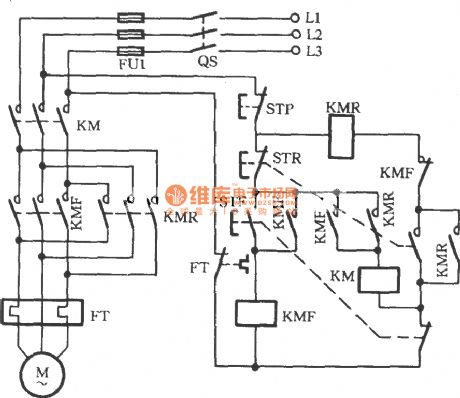
Just as shown in the circuit, the three AC contactors named KMF, KMR and KM are used, which means that each time breaking the motor, the main contact point would grow to four off-points (that is two contacts more than that of the two-contactor). Therefore, it can effectively extinguish the arc of the contactor and can prevent arcing fault.
(View)
View full Circuit Diagram | Comments | Reading(2018)
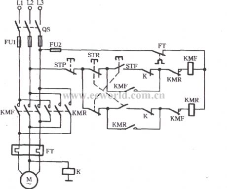
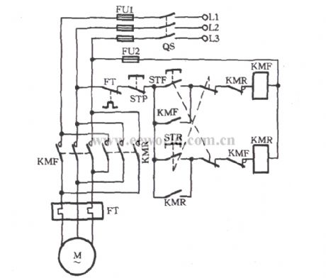
Three-phase motors for jog commutation circuit
Published:2011/7/10 1:08:00 Author:Lucas | Keyword: Three-phase motor, jog commutation
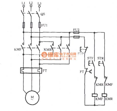
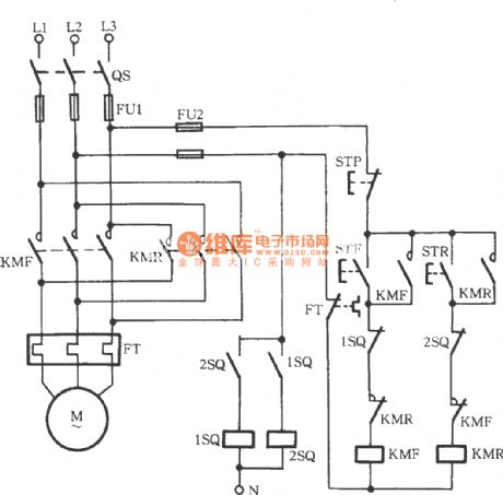
Just shown in the figure, the left circuit is the primary circuit (main circuit) and the right circuit is the secondary circuit (control circuit, the operating circuit). FT is the thermal relay. When STF is pressed, the AC contactor KMF pulls to drive the main contacts of KMF to take action. Then the motor rotates forward (forward). When STF is released, the motor stops working. It is called forward jog . When STR is pressed, KMR pulls to drive the main contact of KlMR to take action. Then the motor rotates in reverse (reverse). When the STR is released, the motor stops rotating. So it is called reverse jog.
(View)
View full Circuit Diagram | Comments | Reading(3348)
The CW168 application circuit of the infrared control
Published:2011/7/8 20:22:00 Author:Seven | Keyword: application circuit, infrared control
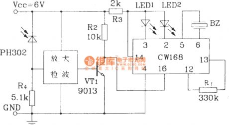
The CW168 application circuit of the infrared control CW168In the figure, the infrared receiver gets the 38kHz modulation signal from the emitter, after the signal is amplified and detected, it is sent to the base pole of VT1, and VT1 is saturated and conducted, CW168 is triggered and getting into work. The circuit can work in single and continuous type or select tones. (View)
View full Circuit Diagram | Comments | Reading(612)
Three-phase motor using proximity switch for automatically stopping inverting circuit
Published:2011/7/9 23:09:00 Author:Lucas | Keyword: Three-phase motor, proximity switch
Just as shown in the circuit, 1SQ and 2SQ both are the non-contact new transistor proximity switch. And STF and STR are respectively forward and reverse button switches. When STF is pressed, KMF pulls to drive the motor to run forward. When it is to a qualified location, the metal plate on the machine rises to close the 1SQ and its internal contacts disconnect to drive the KMF coil to lose power. Then the motor stops. Compared to mechanical limit switch, non-contact transistor proximity switch has better performance, more reliability and longer service life.
(View)
View full Circuit Diagram | Comments | Reading(5330)
The fire alarm circuit with the metal plate as the fog sensor
Published:2011/7/10 10:27:00 Author:Seven | Keyword: fire alarm, metal plate, fog sensor
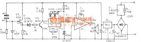
The circuit is shown in the figure, which consists of the fog inducting elements, ON/OFF electric switch, analog sound circuit and AC step-down rectifier circuit, etc. It can be used as the simple fog inducting fire alarm. (View)
View full Circuit Diagram | Comments | Reading(1208)
The alarm circuit
Published:2011/7/8 20:30:00 Author:Seven | Keyword: alarm circuit
View full Circuit Diagram | Comments | Reading(711)
The alarm flashing lamp circuit
Published:2011/7/8 20:39:00 Author:Seven | Keyword: alarm flashing lamp
The circuit includes the AC voltage generator, transformer or transistor AC voltage converter, the power that the flash needs can be adjusted by the potentiometer Rp1 according to need. When the thyristor is blocked, the flash transformer discharges, the capacitor is charged by the 2.2MΩ resistor. When the potentiometer Rp2 smooth contactor voltage is lower than the little Ne pipe, the pipe is conducting, the thyristor is also conducting, so the 0.2μF capacitor discharges, the flashing transformer provides power for the flash pipe. (View)
View full Circuit Diagram | Comments | Reading(632)
Three-phase motor button interlocking for switching circuit
Published:2011/7/9 22:49:00 Author:Lucas | Keyword: Three-phase motor, button
The three-phase motor button interlocking for switching circuit is shown in the figure. This circuit uses a composite button (this is that a button has a pair of normally opened contacts and a pair of normally closed contacts inside, thus ensuring the simultaneous action while being pressed), in order to achieve the button’s interlocking connection. When the motor is running forward, press the button STR to make the KMF lose electricity immediately. And the motor stops and run into the reverse immediately. And vice versa. This not only ensures the not simultaneous action of the reversing contactor KMF and KMR, but also ensure that it start in reverse by directly pressing reverse button rather than the stop button.
(View)
View full Circuit Diagram | Comments | Reading(2958)
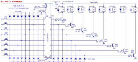
The electric target circuit (exporting to Europe and America, etc)
Published:2011/7/10 8:38:00 Author:Seven | Keyword: electric target circuit
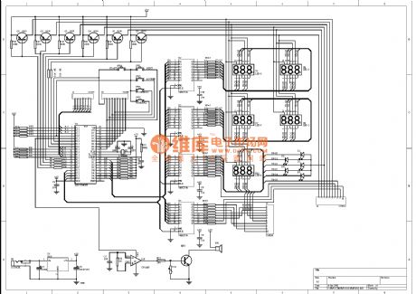
To express thanks to the friends' support, here is to introduce the electric target circuit, which is being produced (to Europe and America, etc) to everybody for reference. As the parts of the source codes and target plate can't be offered, I beg you pardon. This target has five game rules, which allow 1-4 people to play with, and it also has the music and color lamp effect.
(View)
View full Circuit Diagram | Comments | Reading(754)
The auto switch of the TV sound emitter
Published:2011/7/10 8:54:00 Author:Seven | Keyword: auto switch, sound emitter
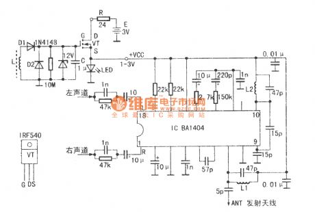
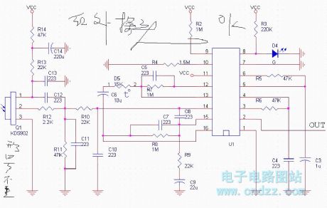
See as the figure, the main circuit is an ordinary single chip FM stereo broadcast emitter integrated circuit BA1404, whose circuit is well known. Both L1 and L2 are covered by the enameled wire of 0.3mm, 5 turns in total. The internal diameter is 3mm, the length is 8mm. With the coil winded according the data, the frequency is 10MHz. In the received range of ordinary radios. The auto part is in the left-upper part of the figure, whose principle is that after the TV set is turned on, there generates a strong magnetic field which is produced by the line scanning system of the tube in the TV set. (View)
View full Circuit Diagram | Comments | Reading(750)
Three-phase motor using the relay to prevent phase short circuit switching circuit
Published:2011/7/9 22:58:00 Author:Lucas | Keyword: Three-phase motor, relay
Just shown in the figure, a relay K is used to connect its coil to the main road. If the primary contact’s adhesion primary live line is with electricity or arc is not extinguished, K pulls to drive the normally closed contacts K to cut off STF and STR loop. So no matter what the forward or reverse button is pressed, the motor can not be started.
(View)
View full Circuit Diagram | Comments | Reading(1389)
The SXTY 3-phase AC booster (closed loop) trigger board circuit
Published:2011/7/10 9:08:00 Author:Seven | Keyword: 3-phase, AC booster, trigger board
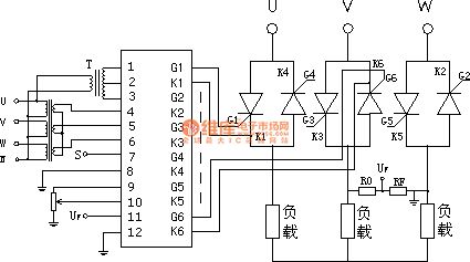
SXTY 3-phase AC booster (closed loop) trigger boards are used in 3-phase AC booster systems as the trigger unit of the SCR, the trigger plate includes the synchronized single detection, closed loop PI regulator and pulse transformer output unit. It can compose the 3-phase AC booster system with the function of voltage regulating output. SXTY 3-phase AC booster plate technology parameters. 1. AC input voltage: dual 18V (AC, 50Hz); input current ≤200 mA; 2.the regulated working voltage range of the main circuit: 380V (AC, 50Hz);3.3-phase synchronized signal input range.
(View)
View full Circuit Diagram | Comments | Reading(4465)
Three-phase motor button and contactor dual-interlock switching circuit
Published:2011/7/9 11:17:00 Author:Lucas | Keyword: Three-phase motor, button, contactor, dual-interlock
Button contactor dual-interlock switching circuit is shown in the figure, which integrates the advantages of the button interlock and the contactor interlock.
(View)
View full Circuit Diagram | Comments | Reading(3086)
The 8-line interlock switch circuit
Published:2011/7/10 9:32:00 Author:Seven | Keyword: interlock switch
The circuit working principle The power supply of the circuit is 12V, which is regulated by IC1(7805) and turned into the 5V power supply. IC2 and the external elements compose the 8-line interlock circuit, the relay J1~J8 compose the switch executing components. The pins of IC2 is marked in the figure. The 1-pin EN is the power terminal, low LEV is effective, so the 1-pin is connected with the earth directly. D1~D8 are the trigger terminals, CP is the clock terminal, Q1~Q8 are the output terminals. When AN1~AN8 are pressed in sequence, the corresponding triggers D1~D8 and CP terminal are in high LEV. (View)
View full Circuit Diagram | Comments | Reading(1742)
The grid circuit of threshold switch
Published:2011/7/10 9:48:00 Author:Seven | Keyword: grid circuit, threshold switch
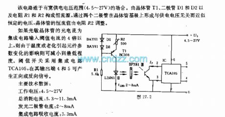
The circuit can be used in situations of wide power supply voltage range 4.5~27V. The constant source of transistor T1, diodeS D1 and D2, resistors R1 and R2 and so on. A voltage which is irrelevant to the power supply but has almost constant voltage is generated on the basic pole of 2 diodes, the constant current is regulated by the resistor R2. If the current of the light sensitive transistor is more than 4 times of the threshold, the effect on the elements caused by the temperature or aging can be minimized.
(View)
View full Circuit Diagram | Comments | Reading(749)
| Pages:1585/2234 At 2015811582158315841585158615871588158915901591159215931594159515961597159815991600Under 20 |
Circuit Categories
power supply circuit
Amplifier Circuit
Basic Circuit
LED and Light Circuit
Sensor Circuit
Signal Processing
Electrical Equipment Circuit
Control Circuit
Remote Control Circuit
A/D-D/A Converter Circuit
Audio Circuit
Measuring and Test Circuit
Communication Circuit
Computer-Related Circuit
555 Circuit
Automotive Circuit
Repairing Circuit