
Circuit Diagram
Index 1588
Illumination Controller (31)
Published:2011/7/7 6:14:00 Author:Sue | Keyword: Illumination, Controller
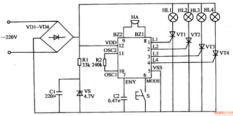
The 220v ac voltage will provide IC with 4.5v direct current working voltage after it is rectificated by VD1-VD4, limited and reduced by R1, stablized by VS, filtrated by C1.
After IC begins to work, its pin 1-4 will output trigger control signals. By controlling the working states of VT1-VW, illumination modes of the illuminations will be changed according to actual requirement. At the same time, IC's inside musical circuit will drive HA to make music directly.
S is the button which controls illumination modes choice and volume. When S is pushed, the illumination modes are changed and HA's volume is changed. (View)
View full Circuit Diagram | Comments | Reading(577)
Illumination Controller (30)
Published:2011/7/7 6:07:00 Author:Sue | Keyword: Illumination, Controller
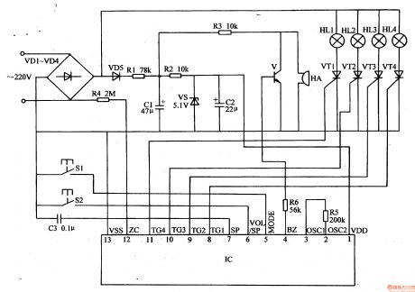
The 220v ac voltage will be put on HL1-H after it is rectificated by VD1-VD4. The other circuit will provide IC with 5v direct current working voltage after it is isolated by VD5, limited by R1,R2, filtrated by C1,C2, stablized by VS. The ac voltage is also put on IC's pin 12 after it is limited and reduced by R4. It can serve as ac synchronizing signals.
IC's pin 8-11(TG1-TG4 terminals) will serve as trigger control signals output terminals. The trigger signals output by these terminals will control the working states of VT1-VW to control the illumination modes of illumination HL1-HL4.
IC's pin 4 (BZ terminals) serve as musical signals output terminal. The musical signals can promote HA to make sound after it is amplified by V.
S1 is illumination modes control button. When S1 is pushed, illumination modes can be changed. (View)
View full Circuit Diagram | Comments | Reading(586)
Illumination Controller (28)
Published:2011/7/7 5:53:00 Author:Sue | Keyword: Illumination, Controller
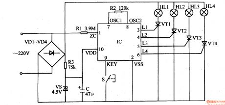
The 220v ac voltage will provide IC with 4.5v direct current working voltage after it is rectificated by VD1-VD4, limited and reduced by R3, stablized by VS, filtrated by C. The other circuit will provide IC's pin 1 with ac synchronizing signal through R1.
After IC begins to work, its pin 3-6(L1-M terminals) will output trigger control signals.By controlling the working states of VT1-VW, HL1-KH will change the illumination modes automatically.
S is manual control button. By pushing S, illumination modes can be choosed manually. (View)
View full Circuit Diagram | Comments | Reading(658)
Illumination Controller (27)
Published:2011/7/7 5:45:00 Author:Sue | Keyword: Illumination, Controller
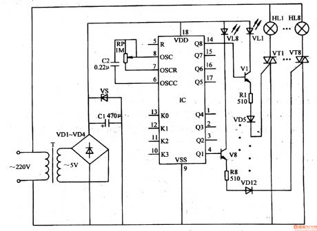
The 220v ac voltage will provide IC with 5v working voltage after it is reduced by T, rectificated by VD1-VD4, stablized by VS, filtrated by C1.
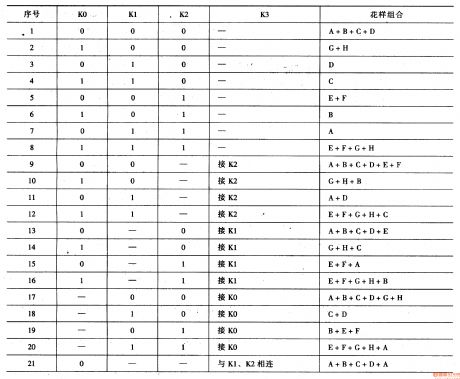
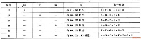
IC's K0-K3 terminals serve as illuminations varied programs set terminals. Q1-Q8 serve as control signals output terminals. When touse the circuit, K0-K3 terminals' connection modes can be changed according to actual requirement(see figure 1-5). The conducting states of V1-V8,VT1-VT8 can be controlled by changing Q1-Q8 terminals' output signals.Then illuminations can twinkle according to the given modes. (View)
View full Circuit Diagram | Comments | Reading(635)
Illumination Controller (26)
Published:2011/7/7 5:33:00 Author:Sue | Keyword: Illumination, Controller
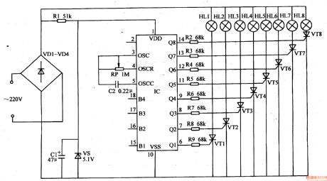
The 220v ac voltage will provide IC with 5v direct current working voltage after it is rectificated by VD1-VD4, limited and reduced by R1, stablized by VS, filtrated by C1.
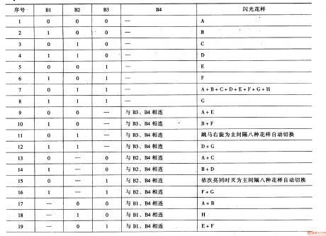
IC's Q1-Q8 serve as control output terminals. B1-B4 terminals serve as various choices control terminals. By changing the connection settings of B1-B4 terminals, the control signals of Q1-Q8 terminals can be changed.
IC's pin 3-5's inside circuit, RP,C2 constitute oscillate circuit. By adjusting RP's resistance value, illumination cycle frequency of illuminations can be changed.
After IC begins to work, its Q1-Q8 terminals will output changing control signal according to the given program. By controlling the connection and disconnection states of VT1-VT8 by R2-R9, HL1-HL8 can twinkle according to the given illumination modes. (View)
View full Circuit Diagram | Comments | Reading(635)
Illumination Controller (25)
Published:2011/7/6 7:16:00 Author:Sue | Keyword: Illumination, Controller
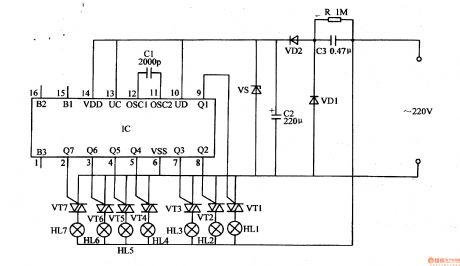
The 220v ac voltage will provide IC with 6v direct current working voltage after it is reduced by C3, rectificated by VD1,VD2, stablized by VS, filtrated by C2.
IC's Q1-Q7 terminals serve as drive signals output terminals. B1-B3 terminals serve as various choices control terminals. Uc and UD serve as consumption control terminals. OSC1 and OSC2 serve as oscillate terminal.
After IC begins to work, its Q1-Q7 terminals will output drive signals which will control the7 circuits of illuminations HL1-HL7 by VT1-VT7.
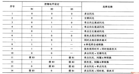
When IC's B1-B3 terminals are not connected, illuminations HL1-HL7's illumination effects are multipoint illumination, as seen in figure 1-3.When the illuminations are used, the illumination effects can be set according to actual requirement. (View)
View full Circuit Diagram | Comments | Reading(632)
555 bumper cars circuit
Published:2011/6/13 7:53:00 Author:nelly | Keyword: bumper car
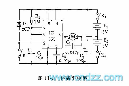
IC adopts ambipolar time base circuit 555, its load current can reach 200mA, it can drive toy motor directly. K1, K2 are toggle switch, when the car moves, K1, K2 are closed, due to 2 foot is high level, 3 foot is low level, the motor terminal's voltage is about 3V(the left is negative, the right is positive), the motor is positive turning, the car moves forward; when the car meets the object, the humper K is butted, 2 foot is connected to ground, the circuit is set, the output turns to high level(about 6V), the motor terminal's voltage is still 3V, but the motor is negative turning, the car gets back. Due to the action of car's reverse wheel, it is moving back and turning. After the circuit is set, C1 is charged by R1, when C1's voltage is charged to more than 6 foot's threshold level 2/3 VDD=2/3(E1+E2)=4V, then the monostable circuit's temporal stability is ended, the car recovers to the former state and moves forward again.
(View)
View full Circuit Diagram | Comments | Reading(1800)
Illumination Controller (24)
Published:2011/7/6 7:00:00 Author:Sue | Keyword: Illumination, Controller
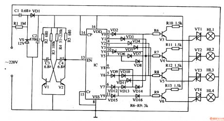
The 220v ac voltage will provide multivibrator, pulse frequency divider, drive control circuit with about 12v direct current voltage after it is reduced by C1, stablized by VS, rectificated by VD1, filtrated by C2.
After the multivibrator begins to work, it generates low frequency pulse signals which will serve as IC's pin 13's count pulse(use the count pulse's reduction trigger counter's method). Under the control of the count pulse, IC's Y0-Y9 terminals will output high level in turn, which will make drive control circuit begin to work through VD2-VD6. The illuminations HL1-HM will be illuminated. (View)
View full Circuit Diagram | Comments | Reading(637)
555 electric bumper cars control circuit
Published:2011/6/13 8:12:00 Author:nelly | Keyword: electric bumper car, control

The monostable timing circuit is composed of time base circuit 555 and R1, C1. When the power supply switch SA1, SA2 are connected, C1 is charged by R1, after 1s, C1's voltage is charged to 2/3 VDD(4V), 555 is in reset state, 3 foot's output is low level, the driving tube VT1 is turned on, the closed circuit is made of motor M and voltage source U1, then the motor M obtains the electricity, M turns into normal positive turning, the electric car moves forward straightly.
When the electric car meets barrier, C1's electricity is diacharged, 555's 2 foot is low level, 555 is set, its 3 foot turns to high level.
(View)
View full Circuit Diagram | Comments | Reading(2068)
555 electric rolling circle game machine circuit
Published:2011/6/13 8:44:00 Author:nelly | Keyword: electric rolling circle, game machine
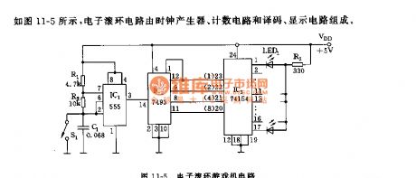
As shown in the figure 11-5, the electric rolling circle circuit is composed of clock generator, counting circuit and coding, display circuit.
The astable multivibrator is composed of 555 and R1, R2, C1, the oscillation frequency f=1.44(R1+2R2)C1, it is about 1000Hz. As IC2's counting clock, its output is added to 14 foot. IC2(74LS93)is TTL type four-bit binary system counter, its 8-4-2-1 code output is added to IC3(74LS154), IC3 is 4-line to 16-line encoder, its 16 output lines take 1 from 16 according to IC2's binary number, and it is low level in order, the circinal 16 LEDs LED1~LED16 are lighted in order, they are chasing rolling ball-shaped.
(View)
View full Circuit Diagram | Comments | Reading(1370)
Metal Proximity Switch
Published:2011/7/7 2:34:00 Author:Felicity | Keyword: Metal Proximity Switch
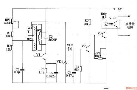
Work of the circuit The circuit consists of high-frequency oscillator circuit, voltage rectifier circuit, and electronic switching circuit. (It is showed in picture 8-131.)High-frequency oscillator circuit consists of high frequency transformer T, potentiometer RPl, resistors Rl-R3, capacitor Cl-C3 and transistor Vl.Voltage rectifier circuit consists of diode VDl and VD2, capacitor C4 and resistor R4.Electronic switching circuit consists of transistor V2 and V3, potentiometer Rm, optocouplers VLC and resistors R5, R6. (View)
View full Circuit Diagram | Comments | Reading(976)
555 automatic reset electric shock protector circuit
Published:2011/6/21 6:43:00 Author:nelly | Keyword: automatic reset, electric shock, protector
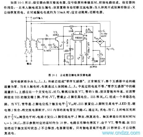
The tube is connected to 555's trigger terminal 2 foot, ordinarily, VT1 tube cuts off, 2 foot is high level. A monostable circuit is composed of 555 and R2, C5. When VT1 tube is turned on, 2 foot level is lower than trigger level 1/3 VDD, 555 is set, 3 foot turns into high level, LED lights, relay J pulls in, the AC power supply is cut off. 555 internal discharge tube is open, C5 is charged by R2, when C5's voltage is higher than 2/3 VDD threshold level, the circuit is reset, 3 foot turns to low level, J releases, it recovers to transmit electricity. After trigger monostable, the delay time td=1.1R2C5, the figured parameter's delay time is about 10s. When the circuit has electric shock, due to VT1 tube is turned on, so 555 is in trigger delay state all the time, J can not release, the power supply is cut off.
(View)
View full Circuit Diagram | Comments | Reading(1936)
Ultrasonic Drilling Machine Two
Published:2011/7/7 2:39:00 Author:Felicity | Keyword: Ultrasonic Drilling Machine
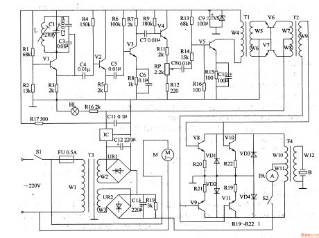
Work of the circuit The circuit consists of power supply circuit, ultrasonic oscillator circuit, pre-amplifier, amplifier and power amplifier drive output circuit. (It is showed in picture 8-125.)Power supply circuit consists of power switch Sl, fuse FU, power transformer m, bridge rectifier, URl and UR2, capacitors C9 and Cll-C13, resistors R16 and R17, voltage regulator diode VS, three-terminal integrated circuit IC and the power light steady HL.Utrasonic oscillator circuit consists of resistors Rl-R4, transistor Vl, Cl-C4 capacitors and inductors L.Pre-amplifier consists of transistor Vl-V5, resistors R5-Rl5, potentiometer RP, capacitors C5-C8 and ClO, and the input transformer Tl.Amplifier consists of Input transformer Tl, T2 and transistor coupling transformer V6, V7.Power amplifier drive output circuit consists of transistor V8-Vll, resistors Rl9-R22, diode VDl-VD4, the control switch S2, ammeter PA, output transformer and transducer B. (View)
View full Circuit Diagram | Comments | Reading(3064)
Ultrasonic Drilling Machine One
Published:2011/7/7 2:37:00 Author:Felicity | Keyword: Ultrasonic Drilling Machine
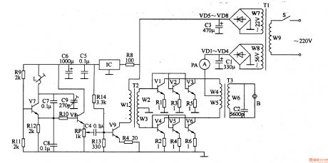
Work of the circuit The circuit consists of power supply circuit, ultrasonic oscillator, driver amplifier and power output circuit. (It is showed in picture 8-124.)Power supply circuit consists of power switch S, the power transformer Tl, rectifier diode VDl-VD8, ammeter PA, resistor R8, three-terminal voltage regulator integrated circuit IC and filter capacitors Cl, C3, C5, C6.Ultrasonic oscillator consists of resistor R9, Rll, Rl2, inductor L, capacitor C7-C9 and transistor V7.Driver amplifier consists of capacitor C4, transistors V8 and V9, n and the input transformer resistor R7, RlO, R13, R14. Power output circuit consists of input transformer M’s windings W2 and W3, power amplifier tube Vl-V6, resistors Rl-R6, the output transformer T3, cap acitor C2 and ultrasonic transducer B
(View)
View full Circuit Diagram | Comments | Reading(2464)
Liquid Level Controller (the 6th)
Published:2011/7/7 21:20:00 Author:Felicity | Keyword: Liquid Level Controller
Work of the circuit
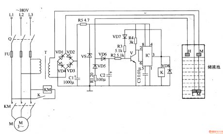
The circuit consists of power circuit, liquid level detection circuit and control implementation circuit. (It is showed in picture 8-104.)
Power circuit consists of Knife switch Q, fuse FU, power transformer T, rectifier diode VDl-VD4, current limiting resistor Rl and R5, filter capacitor Cl and voltage diode VS.
Liquid level detection circuit consists of high level electrode H, low level I electrode and the main electrode M.
Control implementation circuit consists of transistor V, Relay K, time-base integrated circuit IC, diode VD5-VD8 and external RC components. (View)
View full Circuit Diagram | Comments | Reading(3320)
Liquid Level Controller (the 5th)
Published:2011/7/7 21:18:00 Author:Felicity | Keyword: Liquid Level Controller
Work of the circuit
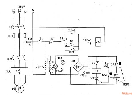
The circuit consists of power circuit and level detection and control circuit. (It is showed in picture 8-103.)
Power circuit consists of knife switch Q, fuse FUl, FU2, the power switch Sl, the power transformer T, to bridge rectifier UR and filter capacitor C.
Level detection and control circuit consists of reed SAl, SA2, relay Kl, Pakistan, Journal of crystal tube VT, resistor R, AC contactor KM, thermal relay KR, control button S2, sweet and manual / automatic control switch S3.
(View)
View full Circuit Diagram | Comments | Reading(993)
Liquid Level Controller (the 4th)
Published:2011/7/7 21:17:00 Author:Felicity | Keyword: Liquid Level Controller
Work of the circuit
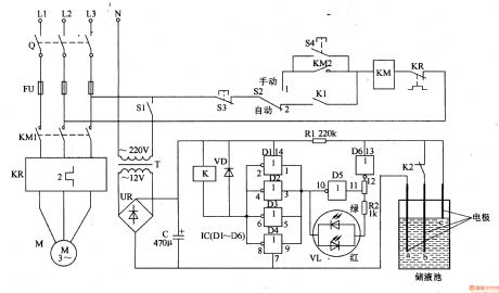
The circuit consists of power supply circuit, liquid level detection control circuit and indication starting control circuit. (It is showed in picture 8-102.)
Power supply circuit consists of Power transformer T, to bridge rectifier and filter capacitor C.
Liquid level detection control circuit consists of Liquid level detection electrode a-c, six non-gate IC IC (D1-D6), resistors Rl, R2, relay K, color light-emitting diodes VL and diode VD.
Indication starting control circuit consists of switch Q, fuse FUl-FU3, power switch Sl, manual / automatic control switch S2, the stop button S3, called the start button, AC contactors KM and thermal relays KR. (View)
View full Circuit Diagram | Comments | Reading(903)
555 DC regulated power supply protection device circuit
Published:2011/6/21 6:22:00 Author:nelly | Keyword: DC regulated power supply, protection device
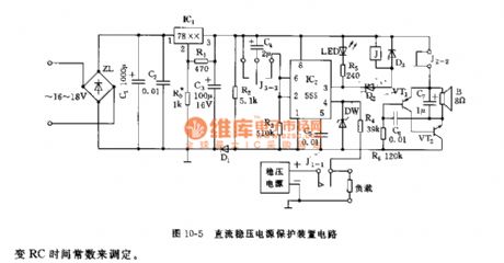
The protector consists of depressurization regulated power supply, VDD=+(5~12)V, it depends on which voltage stablizing unit is adopted by IC1. The controllable monostable delay circuit is composed of IC2(555) and C4, R3. Ordinarily, due to J1-1 is short connected, when the load is normal, 4 foot level is higher than 1V; when it is short circuit, 4 foot is low level(<0.6V), 555 is in forced reset state, 3 foot is low level, J pulls in, J1-1 is cut off quickly, the short circuit's load is turned off. At the same, J3-3, J2-2 contacts are turned on, the audio frequency feedback type oscillator which is made of VT1, VT2, C6, C7, R6 obtains electricity and oscillates, it sends out about 1000Hz audio. J3-3 is connected, C4 is charged, then 555's 2 foot level is lower than 1/3 VDD, 555 is set, J releases, J1-1 normally closed contact is turned on again.
(View)
View full Circuit Diagram | Comments | Reading(1425)
Timing Controller (the 1st)
Published:2011/7/7 22:29:00 Author:Felicity | Keyword: Timing Controller
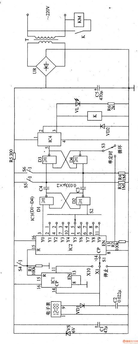
Work of the circuit
The circuit consists of Power supply circuit, the clock signal generator, counting distributor circuit, flip-flop circuit and control output circuit. (It is showed in picture 8-90.)
Power supply circuit consists of Power transformer T, bridge rectifier, UR, filter capacitor Cl, C5, current limiting resistor R5 and Zener VS.
The clock signal generator consists of electronic clock, diodes VDl, capacitor C2 and the count divider integrated circuit ICl.
Counting distributor circuit consists of count divider integrated circuit IC2, resistors Rl, R2, timer selection switch Sl, S2 and reset button S4.
Flip-flop circuit consists of NAND gate integrated circuit IC3 (Dl-D4) and capacitor C3, C4, resistor R3, R4, the Close button S5, S6 on the button and loop / single timer switch S3.
Control output circuit consists of electronic switch integrated circuit IC4, diode VD2, relay K, light-emitting diode VL, resistors R6 and AC contactor KM. (View)
View full Circuit Diagram | Comments | Reading(757)
555 touching SCR zero-crossing switch circuit(2)
Published:2011/6/14 3:04:00 Author:nelly | Keyword: touching SCR, zero-crossing switch
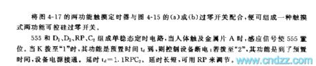
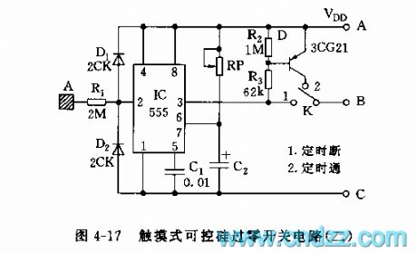
The monostable timing circuit consists of the 555 and D1,D2,RP,C2. The inductive signal makes the 555 reset when thebody touches the metal disc A. When the k contacts 1 and the pre-set time reaches td, it can make the control equipment power-off. If the K contacts 2 , the DPS will be on-state when the pre-set time reaches. td=1.1RPC2. we can use the RP to regulate through the td's long/short.
(View)
View full Circuit Diagram | Comments | Reading(2756)
| Pages:1588/2234 At 2015811582158315841585158615871588158915901591159215931594159515961597159815991600Under 20 |
Circuit Categories
power supply circuit
Amplifier Circuit
Basic Circuit
LED and Light Circuit
Sensor Circuit
Signal Processing
Electrical Equipment Circuit
Control Circuit
Remote Control Circuit
A/D-D/A Converter Circuit
Audio Circuit
Measuring and Test Circuit
Communication Circuit
Computer-Related Circuit
555 Circuit
Automotive Circuit
Repairing Circuit