
Circuit Diagram
Index 1596
Epica engine module power ground connection, serial data and failure indicator light circuit
Published:2011/7/6 21:14:00 Author:Christina | Keyword: Epica, engine, module power, ground connection, serial data, failure indicator light
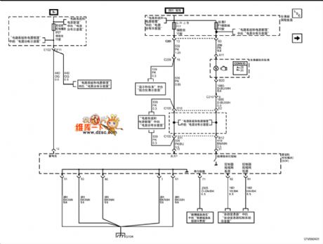
The Epica engine module power ground connection, serial data and failure indicator light circuit is as shown in the figure:
(View)
View full Circuit Diagram | Comments | Reading(694)
The input protection circuit of AD8362
Published:2011/7/6 21:07:00 Author:Christina | Keyword: input, protection circuit
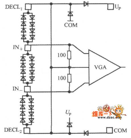
The input protection circuit of AD8362 is as shown in the figure. You can connect two groups of composite diode reverse polarity between the IN+ and IN- in parallel, so it plays the clamping protection function to avoid the damage that is caused by the instantaneous high voltage. In addition, there are the diode clamping protection circuits between the pins of DECL1 and IN+ or the IN- and DECL2.
(View)
View full Circuit Diagram | Comments | Reading(663)
Epica engine data sensor-pressure and temperature circuit
Published:2011/7/6 21:00:00 Author:Christina | Keyword: Epica, engine data sensor, pressure, temperature
The Epica engine data sensor-pressure and temperature circuit is as shown in the figure:
(View)
View full Circuit Diagram | Comments | Reading(547)
Epica engine data sensor-oxygen sensor circuit
Published:2011/7/6 20:59:00 Author:Christina | Keyword: Epica, engine data sensor, oxygen sensor
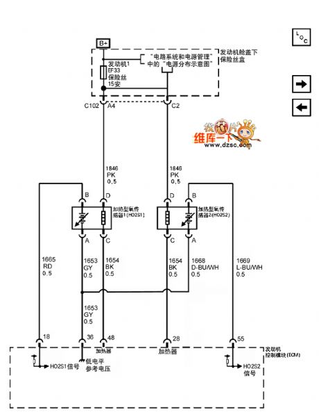
The Epica engine data sensor-oxygen sensor circuit is as shown in the figure:
(View)
View full Circuit Diagram | Comments | Reading(700)
Power measurement system demodulating circuit
Published:2011/7/6 20:55:00 Author:Christina | Keyword: Power measurement system, demodulating circuit
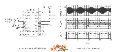
You can use the AD8362's UTGT port to form the demodulating circuit, this circuit can take out the envelope of the RF AM wave and revert it into the intermediate and low frequency signals. The demodulation circuit and the envelope process are as shown in figure (a) and (b). Here we suppose the input signal is the modulated 100kHz sine wave, the carrier frequency is 100 MHz. If you connect the 1.25V (average) voltage VT to the pin-14, the output voltage of pin-12 is the modulated 100kHz sine wave signal.
(View)
View full Circuit Diagram | Comments | Reading(2544)
Microtek MRS-1200TP scanner switching power supply circuit
Published:2011/7/6 21:52:00 Author:Christina | Keyword: Microtek, scanner, witching power supply
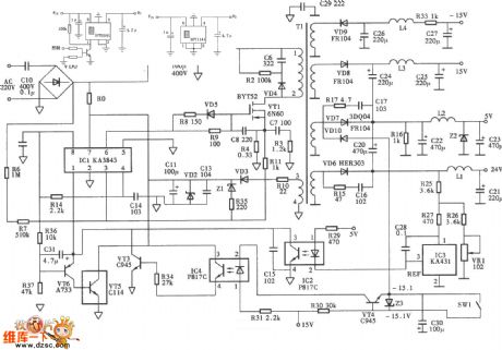
Figure:Microtek MRS-1200TP scanner switching power supply circuit
(View)
View full Circuit Diagram | Comments | Reading(3141)
Temperature measurement circuit composed of the AD7714 and the thermocouple
Published:2011/7/6 21:46:00 Author:Christina | Keyword: Temperature measurement, thermocouple
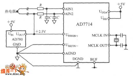
The temperature measurement circuit which is composed of the AD7714 and the thermocouple is as shown in the figure. In this application, the AD7714 operates in the buffer mode, this mode can connect with the decoupling capacitor at the front port to filter the noise on the thermocouple leads. In the buffer mode, the common mode range of AD7714 is narrow, in order to make the differential voltage of the thermocouple in the right common-mode voltage range, the AIN2 input port of the AD7714 should be offset to the +2.5V benchmark voltage.
(View)
View full Circuit Diagram | Comments | Reading(910)
Bora fog light and headlight cleaning pump circuit
Published:2011/7/6 21:40:00 Author:Christina | Keyword: Bora, fog light, headlight, cleaning pump
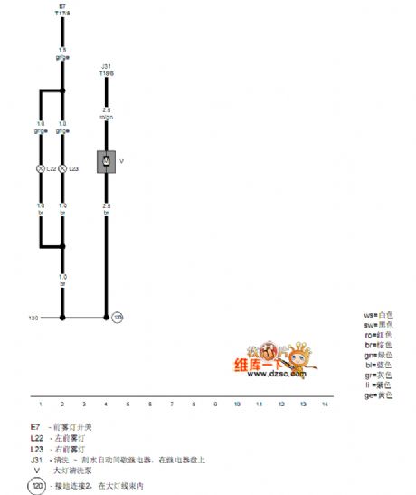
The Bora fog light and headlight cleaning pump circuit is as shown in the figure:
(View)
View full Circuit Diagram | Comments | Reading(489)
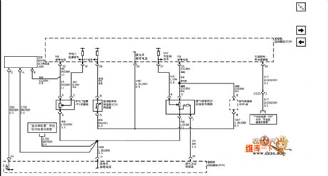
Epica engine cooling system circuit
Published:2011/7/6 21:34:00 Author:Christina | Keyword: Epica, engine, cooling system
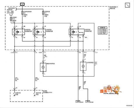
The Epica engine cooling system circuit is as shown in the figure:
(View)
View full Circuit Diagram | Comments | Reading(837)
The infrared detection alarm circuit
Published:2011/7/7 0:21:00 Author:qqtang | Keyword: infrared detection alarm
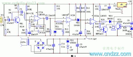
Working principles
The circuit principle is in figure 1, which consists of the infrared sensor, signal amplifier circuit, voltage comparator, time delay circuit and stereo alarm circuit, etc. When the sensor IC1 detects the infrared signal emitted from the human body, the 2-pin of IC1 is outputting a weak electric signal which is firstly amplified by the first-stage amplifier circuit composed of VT1 and so on, and then it is sent to the computing amplifier IC2 by C2 for gain expansion and low-noise amplification, at the moment, the signal output by 1-pin of IC2 is strong enough. (View)
View full Circuit Diagram | Comments | Reading(830)
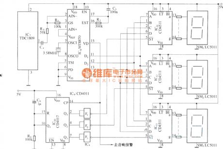
The infrared detection multi-channel alarm circuit(TDC1808/TDC1809)
Published:2011/7/7 0:31:00 Author:qqtang | Keyword: infrared detection, multi-channel alarm
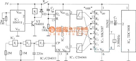
emitting circuit:
receiving circuit:
(View)
View full Circuit Diagram | Comments | Reading(690)
The microwave detection wireless alarm (S&P27)
Published:2011/7/7 0:40:00 Author:qqtang | Keyword: microwave, detection, wireless alarm

In figure (a), when the detecting circuit TWH9250 is detecting the object signal, the terminal O is outputting a low LEV, and the relay K is connected. After the emitting circuit is connected with the power supply, the address code programmed by YYH26 is amplified by S&P27A and then emitted into the sky through the aerial. The detecting circuit is used to link to the working power source of the emitter, the address code emitted by the circuit represents the position of the emitter. In figure (b) is the multi-channel reception alarm circuit. (View)
View full Circuit Diagram | Comments | Reading(1078)
The microwave language burglarproof alarm
Published:2011/7/7 0:12:00 Author:qqtang | Keyword: language burglarproof alarm
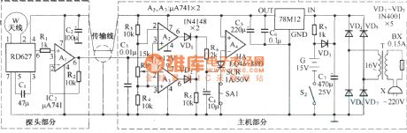
The microwave language burglarproof alarm is fitted in homes, shops, storerooms, orchestras and so on. When someone is going into the alert area, it will make the sound of catch the thief . To prevent it from being broken, there are functions of breakdown alarm and AC/DC power auto shift in it. The principle of the circuit is shown in the figure. The alarm consists of the probe and the host. The probe consists of the microwave sensing module RD627 and op-amp A1, the output signal of RD627 is amplified by A1 and then connected with the host by the dual chip shield cable.
(View)
View full Circuit Diagram | Comments | Reading(733)
The pocket-sized money drawer burglarproof alarm circuit
Published:2011/7/6 23:53:00 Author:qqtang | Keyword: pocket-sized, money drawer, burglarproof alarm
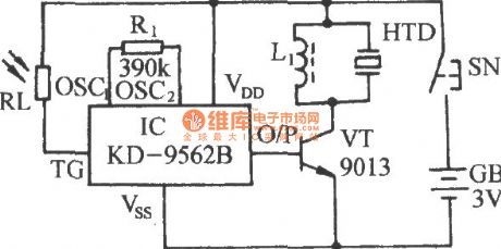
The figured circuit is assembled on the base of a light control alarm analog sound integrated circuit KD-9562B. Its size is small, just like a watch box, the number of the external elements is 5, which can be used in the drawer or wallet as the burglarproof alarm. (View)
View full Circuit Diagram | Comments | Reading(968)
The new style flashing alarm integrated application circuit
Published:2011/7/6 20:55:00 Author:qqtang | Keyword: flashing alarm, integrated application circuit
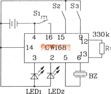
The new style flashing alarm integrated application circuit R1 is an external resistor of the internal oscillator, by changing the resistance of R1, the frequency of the internal oscillator in IC can be changed, when R1=330kΩ, the output flashing frequency of IC is 4Hz, and the IC will stop working in 16s after it is triggered. To strengthen the sound effect, a power triode can be connected with the output terminal, which can drive the loudspeaker play back. Besides, CW168 can be triggered by all kinds of control circuits, so the auto control can be fulfilled. (View)
View full Circuit Diagram | Comments | Reading(642)
The small-capacitor and long-time timer of touch type
Published:2011/7/6 21:46:00 Author:qqtang | Keyword: small-capacitor, long-time timer
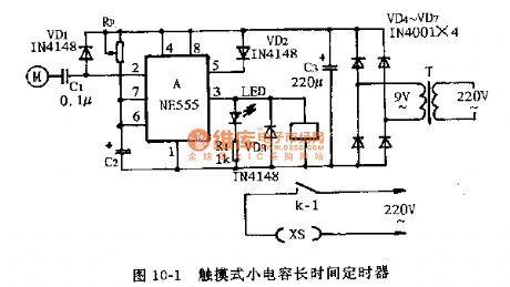
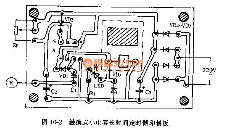
1.The small-capacitor and long-time timer of touch typeHere is to introduce a new small-capacitor and long-time timer of touch type, as it fixes the LEV on 5-pin of the control terminal in the time-based circuit, so the capacitor can get the time of several hours when its value is not large. The other feature of the circuit is that it is touch control, just touch the electrode plate with the finger, the timer will be triggered and gets into work.
(circuit principle) The small-capacitor and long-time timer of touch type is shown in figure 10-1.
(View)
View full Circuit Diagram | Comments | Reading(790)
The touch type alarm circuit
Published:2011/7/6 21:56:00 Author:qqtang | Keyword: touch type, alarm circuit
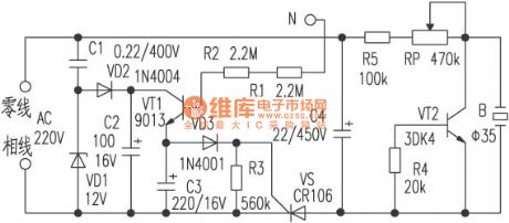
Circuit principleThe touch type alarm circuit is shown in the figure, which consists of the power supply circuit, touch delay circuit, SCR switch circuit and negative resistance oscillator, 4 parts in total.The power supply circuit consists of VD1,VD2,C1,C2 and so on, which provides for the touch delay circuit with a 12V DC working current. The touch delay circuit consists of VT1 and so on, usually, VT1 is in blocked state, SCR VS is disable state without trigger voltage, the next circuit is not working without power.
(View)
View full Circuit Diagram | Comments | Reading(737)
The anti-robbery alarm (RCM1A/RCM1B is the reception/emitting module)
Published:2011/7/6 22:09:00 Author:qqtang | Keyword: anti-robbery alarm, reception/emitting module
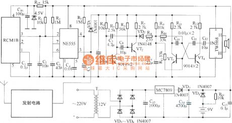
The circuit consists of the wireless emitter and reception control alarm. The emitter is powered by the button cell, whose size is small and it's easy to carry. Once something happened, just press the emitter key, the receiver would make loud alarm noise. The emitter circuit consists of the emitter RCM1A, button cell and emitting key; the wireless reception alarm consists of reception module RCM1B, the single steady trigger, compound oscillating circuit, audio booster and loudspeaker, power supply circuit and so on. (View)
View full Circuit Diagram | Comments | Reading(812)
The household fuel gas alarm circuit
Published:2011/7/6 22:36:00 Author:qqtang | Keyword: household, fuel gas alarm
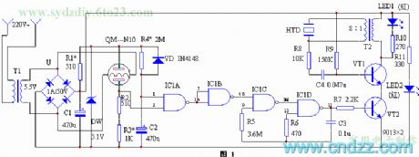
The working principle of the device circuit is shown in figure 1. The circuit consists of the power supply circuit, sensor circuit, voltage control oscillator and alarm circuit, etc. The 220V mains is dropped to 5.5V or so by the power supply transformer T1, which is taken directly as the heating voltage of the sensor QM-N10 without rectification and filter. The control circuit is powered after it is rectified by U and filtered by C1. The resistance of the air sensitive resistor sensor QM-N10 is about dozens of kΩ in clean air, when it contacts with harmful gas, the conductance will rise up. (View)
View full Circuit Diagram | Comments | Reading(734)
The household appliance over-voltage protector circuit
Published:2011/7/6 22:47:00 Author:qqtang | Keyword: over-voltage protector, household appliance
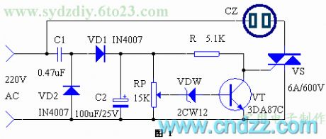
The working principle of the device circuit is shown in figure 1. After the AC mains is stepped down and limited by capacitor C1, it is then rectified by VD1 and VD2, and then filtered by C2, finally, a 12v or so DC voltage is acquired. When the grid is normal, the regulated LED VDW can't be broken down and conducted, at this moment, triode VT is in the blocked state, the dual-way SCR VS is triggered and conducted, so the appliance connected with the outlet XS is getting power and work. If the voltage of the grid is rising up suddenly, over 250V, the voltage on the central point of RP will break down VDW. (View)
View full Circuit Diagram | Comments | Reading(1051)
| Pages:1596/2234 At 2015811582158315841585158615871588158915901591159215931594159515961597159815991600Under 20 |
Circuit Categories
power supply circuit
Amplifier Circuit
Basic Circuit
LED and Light Circuit
Sensor Circuit
Signal Processing
Electrical Equipment Circuit
Control Circuit
Remote Control Circuit
A/D-D/A Converter Circuit
Audio Circuit
Measuring and Test Circuit
Communication Circuit
Computer-Related Circuit
555 Circuit
Automotive Circuit
Repairing Circuit