
Circuit Diagram
Index 1589
555 touching bistability Controller circuit
Published:2011/6/14 4:13:00 Author:nelly | Keyword: touching, bistability Controller
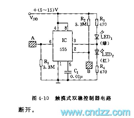
As shown on the figure 4-10, the 555 is the core of this circuit. It uses the 555's 6 foot to contact the comparator A1's in-phase and inverted input of the interior substrate. It can change the output state through controlling the reset and set. When touching the metal disc A, the 555 will be reset, the LED1 will light on and the LED2 will light off. When touching the metal disc B, the LED2 will light on and the LED1 will light off. If changing the relay, we can achieve the control of the executive circuit's power.
(View)
View full Circuit Diagram | Comments | Reading(981)
The ultraviolet fire sound/light alarm equipment circuit
Published:2011/7/8 2:27:00 Author:Seven | Keyword: ultraviolet, alarm equipment
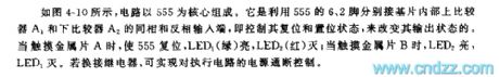
See as the figure, the circuit consists of the ultraviolet sensor Buv, the single stable trigger circuit, anti-false alarm judging circuit, fire fighting truck sound making alarm circuit and AC step-down rectifier circuit, etc. (View)
View full Circuit Diagram | Comments | Reading(750)
Automotive Fuel Monitor Three
Published:2011/7/7 9:47:00 Author:Felicity | Keyword: Automotive Fuel Monitor
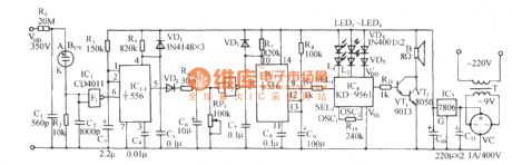
While the oil level drops down, the position of the slider of RP1 goes down correspondingly to make the voltage of pin 5 of IC2 drops. The output pins output high voltage one by one and then VL1-VL10 extinguish one by one in descending order( VL10,VL9,….VL1) to indicate the oil level linearly. And the driver can know the amount of fuel directly from the LEDs which are still on.While the oil level is at its lowest (i.e. pin 1 of IC2 is high level, and VL1 is off),V1 is saturated and on to make VL11 shine. As VL11 shines, V2 periodically turns on and off to make HA send out alarm. (View)
View full Circuit Diagram | Comments | Reading(635)
USB switching to RS232 dual serial port circuit
Published:2011/7/7 7:21:00 Author:Fiona | Keyword: dual serial port
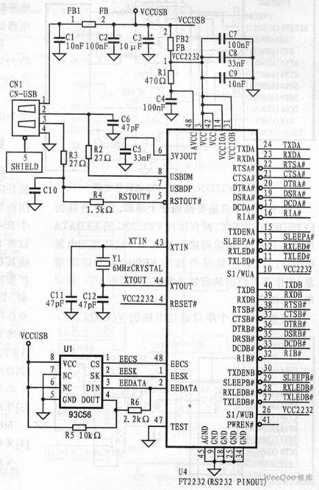
It needs to pay attention to the following points when designing:First of all:the resistance of the FT2232C's USBDP,USBDM two input terminals' resistors must be equal,the typical value is 27Ω, and the resistors must be 1% precision resistors,otherwise they easily lead to input impedance mismatch so that the circuit can not work normally.Secondly,at both ends of the 2 the capacitance of two capacitors which are at both ends of the circuit oscillator must be equal too, typical value is 27pF.Due to the design requirement is to get 2 serial port, thus extrapolated EEPROM can not answer, but directly connect the EEDATA terminal of FT2232C to VCC by 10kΩ resistor.
(View)
View full Circuit Diagram | Comments | Reading(902)
Using IRFP250 power tube H-bridge motor drive circuit
Published:2011/7/8 2:42:00 Author:Fiona | Keyword: power tube, H-bridge motor drive
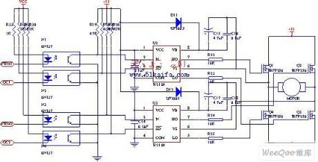
The drive circuit of electromotor includes a FET bridge circuit, FET base drive circuit,current sensor of motor drive circuit and the relay. FET bridge circuit mainly consists of four high-power MOSFET power tubes,it requires that the power tubes have good switching characteristics,can withstand higher drive current and have a long life.According to motor power parameters and power tube limit parameters and the electrical characteristics,we use four the same N-channel IRFP250power tubes to form the H-bridge circuit.
(View)
View full Circuit Diagram | Comments | Reading(6987)
Automotive Fuel Monitor One
Published:2011/7/7 8:18:00 Author:Felicity | Keyword: Automotive Fuel Monitor
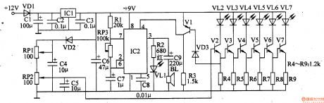
While the fuel tank is full of fuel, the resistance of RP2 slides to the minimum value under the force of buoy. And V2-V7 are all on, and then LED VL2-VL7 light up.While the fuel tank is half full, RP2 slide to the middle and V2-V4 are on, V5-V7 are cut off. VL2-VL4 is still on, but VL5-VL7 is off.While the amount of fuel is below the limit value, the resistance of RP2 is at the maximum value. V2-V7 are cut off and V1 is on. Pin 4 of IC2 is at high level and then the oscillator works. Pin 3 of IC2 is at low level to make LED VL1 shine and BL send out alarm.It indicates there is hardly fuel when only the yellow LED VL2 is on. (View)
View full Circuit Diagram | Comments | Reading(555)
Controlled by single chip DC brushless motor driver and interface circuit
Published:2011/7/8 2:42:00 Author:Fiona | Keyword: Controlled by single chip, DC brushless motor, driver and interface
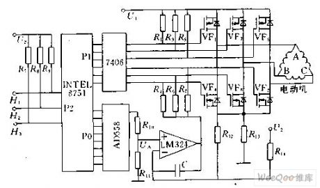
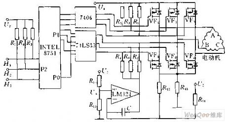
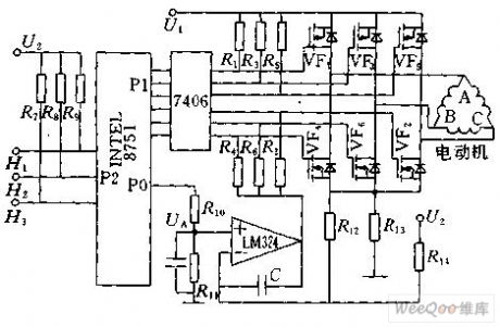
Figure 1 shows the functional block diagram of using 8751 single chip to control the brushless DC motor.8751's P1 is connected with the 7406 inverter control to control the brushless DC motor commutation,P2 is used for measuring the signal H1, H2, H3 from position sensor,P0 externally connects a digital to analog converter.According to the commutation of stator windings, first it needs to find the state of three rotor magnet position sensor signals H1,H2,H3 and the relationship between 6 power tubes,then it puts the information in tabular form to the single-chip's EEPROM.
(View)
View full Circuit Diagram | Comments | Reading(3046)
220V power supply LED lamp driver circuit
Published:2011/7/8 2:41:00 Author:Fiona | Keyword: 220V power supply, LED lamp driver
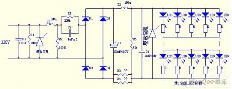
In the circuit,C1,R1,piezoresistor,L1,R2 form the primary power supply filter circuit,it can be able to filter the input instant high voltage,C2,R2 form step-down circuit,C3,C4,L2 and piezoresistor form the filter circuit after rectifying. This circuit uses a dual filter circuit,it can effectively protect the LED not be breakdown and damage by instant high voltage.
(View)
View full Circuit Diagram | Comments | Reading(6606)
Saving lighting control circuit
Published:2011/7/8 1:33:00 Author:Fiona | Keyword: Saving lighting
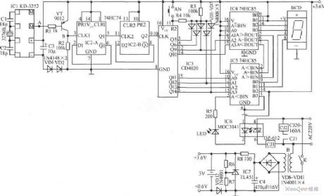
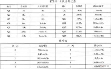
At time t1,the M of IC1 is in a high impedance state, VT cuts off; at the time t2, the M of IC1 outputs the negative pulse, VT conducts and outputs qualified clock signal CLK1 from VT collector. IC2 is a dual D flip-flop,it feedbacks the reversed output terminalto the data input terminal D to connect 2 divider, the data output terminal Q1 of IC2-A and clock input terminal CLK2 of IC2-B are connected to make up a 4 divider, the 4-frequency signal inputs into IC3 to do 14 divide, so that the second signal does 18 divide, the 14 divide state of the IC3 is shown in table.
(View)
View full Circuit Diagram | Comments | Reading(724)
Liquid Level Controller (the 3rd)
Published:2011/7/7 21:16:00 Author:Felicity | Keyword: Liquid Level Controller
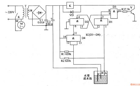
Work of the circuit
The circuit consists of power circuit, liquid level detection circuit and control implementation circuit. (It is showed in picture 8-101.)
Power circuit consists of power transformer T, rectifier diode VDl-VD4 and filter capacitor C.
Liquid level detection circuit consists of high-level electrode A, low-level electrode B and the main electrode C.
Control implementation circuit consists of relay K, the control transistor V and AC contactor KM. (View)
View full Circuit Diagram | Comments | Reading(2104)
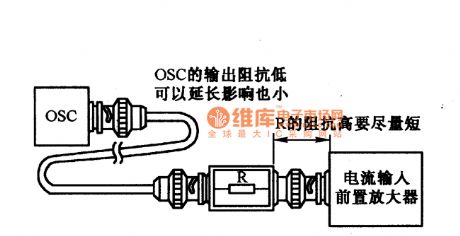
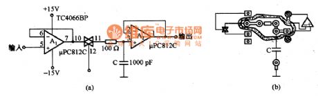
Noise circuit diagram of processing feeble signal
Published:2011/6/16 23:59:00 Author:Sophia | Keyword: Noise circuit, Processing feeble signal
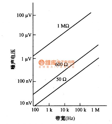
When designing the circuit of processing feeble AC signal, the key proplem of restricting performance is noise. The noise can be classified as three types: th ermal noise from signal source, the noise from the interior and exterior of electrical device. External noise has a transmission line noise, electrostatic noise coupling, electromagnetic coupling noise, radio noise and radiation, physical vibration, heat, light and other form of noise. Thermal noise is formed from the irregular movement of free electrons inside conductor. Thermal noise voltage Vn = 4KTRB, among which, K is Boltzmann constant (1.38x1O-23JK), T is thermodynamic temperature (K), R is the resistance value (Ω), B is the bandwidth product (HZ). From the above equation, thermal noise and the thermodynamic temperature, resistance, and bandwidth is proportional to the square root of the product. Thermodynamic temperature is calculated at T = 300.
. (View)
View full Circuit Diagram | Comments | Reading(710)
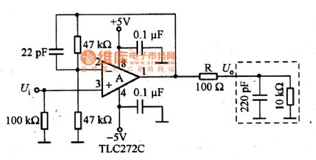
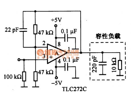
Processing on Capacitive loading circuit diagram
Published:2011/6/16 5:27:00 Author:Sophia | Keyword: Capacitive loading, Processing
(View)
View full Circuit Diagram | Comments | Reading(648)
CMOS Operational amplifier inphase amplifier circuit diagram
Published:2011/6/14 7:58:00 Author:Sophia | Keyword: CMOS Operational amplifier, inphase amplifier
(View)
View full Circuit Diagram | Comments | Reading(681)
Liquid Level Controller (the 1st)
Published:2011/7/7 21:06:00 Author:Felicity | Keyword: Liquid Level Controller
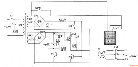
Work of the circuit
The circuit consists of power circuit and level detection and control circuit. (It is showed in picture 8-99.)
Level detection and control circuit consists of detection electrodes,-c, control buttons S2, S3, resistors Rl-R4, transistor Vl, V2, light-emitting diode VLl, VL2, relay K, AC contactor KM and diode VD.
(View)
View full Circuit Diagram | Comments | Reading(978)
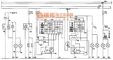
The rear foglight, defrosting and scraping water theory circuit of 70 road vehicle of Toyota Land Cruiser
Published:2011/6/27 2:48:00 Author:Sophia | Keyword: The rear foglight, defrosting, scraping water theory circuit, 70 road vehicle of Toyota Land Cruiser
Screws commonly used in exterior of lighting to adjust headlamp beam, which is very inconvenient. Japan's Lexus sedan (E5300, Lexus LS400) and the Land Cruiser off-road vehicles all use electronical control to adjust.
Light ball in light bowl have a fairly large space. It uses electromotor to change the place of the light ball (light) in the reflecting mirror to adjust the beam. It can be imagined that the fixing device and Headlamp beam of the bulbs in the interior of lights is more complex.
Figure 1 shows the regulator current from the electromotor of actuating mechanism of fuse F13 (129 relay access from the rear) belongs to the permanent magnet motor, as long as the armature current commutates, the motor rotation will change. Two of relays can be used to change the current direction. When electromotor armature does not work, both ends of the armature phase often combine with electrical contacts. Both ends connecting with the iron can make an effect on dynamic to ensure positioning whiling stopping after adjustment. (View)
View full Circuit Diagram | Comments | Reading(1683)
Small-signal circuit diagram under experiment circumstance
Published:2011/6/16 23:46:00 Author:Sophia | Keyword: Small-signal circuit, Under experiment circumstance
(View)
View full Circuit Diagram | Comments | Reading(628)
Engine Water Supply Alarm Four
Published:2011/7/7 7:34:00 Author:Felicity | Keyword: Engine Water Supply Alarm
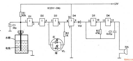
When the water level of the tank is above the lowest water level, electrode is connected to ground (the iron) through the resistance of water. And the input voltage of D1 is low; the output voltage of D2 is low and the output voltage of D3 is high. The green LED inside VL is on. And the output voltage of D4 is low; VD is on; the audio oscillator consists of D5, D6, R3 and C2 doesn’t work, HA is noiseless.When the water level is the same as the lowest water level (i.e. the electrode is just above the water), the output of D3 is at high level and the green LED inside VL is on while the green on is off. And the output of D4 is at high level to make VD cut off and then the audio oscillator works, then HA send out beeps.
(View)
View full Circuit Diagram | Comments | Reading(787)
The warm-up time and the charge(2LT type, 2L diesel engine) theory circuit of 70 light sport utility vehicle of Toyota Land Cruiser
Published:2011/6/26 4:31:00 Author:Sophia | Keyword: Warm-up time, Charge(2LT type, 2L diesel engine), theory circuit, 70 light sport utility vehicle of Toyota Land Cruiser
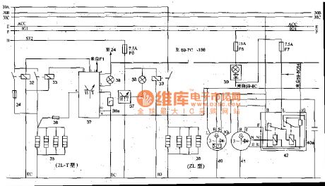
Off-road vehicles with a 2L-T type or 2L diesel engine, in general,fit the electric plug inside the cylinder. the glow plugs 35 is controlled by the relay 33, relay coil 33 is controlled by the warm-up timer 37. Warm-up timer work when plug 38a installed in the cooling system inputs the water temperature. When the water temperature is above 5 ℃, if the ignition switch is switched on, preeat indicator light will flash about 38 (about 0.3S), which means that can be started directly; if the water temperature is below 5 ℃, the preheat light 38 will stay on for an period of time (about 18S), until the temperature of warm-up plugs inside the cylinder reaches 800 ℃ or so and lights is off, which shows the vehicle can be started. 70 light-duty off-road vehicle also is equipped with emission control systems. When the water temperature is low, the fuel will have poor atomization, incomplete combustion production is excessive. Emission controller 46 will control the throttle idle switch electromagnetism valve 44, while make the cold mixture heater work and heat up atomization. (View)
View full Circuit Diagram | Comments | Reading(2552)
Input end protection circuit of dual power operational ampplifier
Published:2011/6/20 2:25:00 Author:Sophia | Keyword: Dual power operational ampplifier, Input end protection
(View)
View full Circuit Diagram | Comments | Reading(557)
In-phase sample-and-hold circuit
Published:2011/6/19 23:32:00 Author:Sophia | Keyword: In-phase, sample-and-hold circuit
(View)
View full Circuit Diagram | Comments | Reading(675)
| Pages:1589/2234 At 2015811582158315841585158615871588158915901591159215931594159515961597159815991600Under 20 |
Circuit Categories
power supply circuit
Amplifier Circuit
Basic Circuit
LED and Light Circuit
Sensor Circuit
Signal Processing
Electrical Equipment Circuit
Control Circuit
Remote Control Circuit
A/D-D/A Converter Circuit
Audio Circuit
Measuring and Test Circuit
Communication Circuit
Computer-Related Circuit
555 Circuit
Automotive Circuit
Repairing Circuit