
Circuit Diagram
Index 1593
The Bora rear window wiper motor, head/rear window washing pump circuit
Published:2011/7/7 21:37:00 Author:Seven | Keyword: Bora, rear window, wiper motor, washing pump
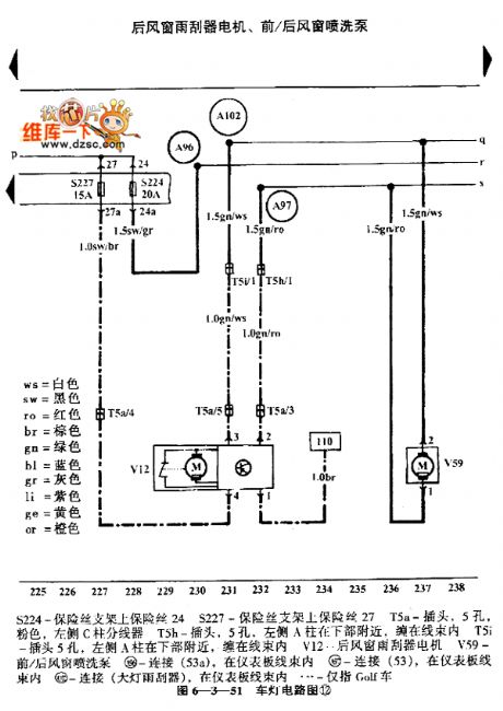
The Bora rear window wiper motor, head/rear window washing pump circuit is shown as above.S224-the fuse on the holder 24 S227- the fuse on the holder 27 T5a-plug, 5 holes, pink, the wire distributor of pillar C on the left T5h-plug, 5 holes, near the bottom of the left pillar A, in the wire bundle T5i-plug, 5 holes, near the bottom of the left pillar A, in the wire bundleV12-the rear window wiper motor V59-the head/rear window washing pump 156-connector(53 a), in the wire bundle of the instrument Figure 6-3-51 the vehicle lamp circuit (12) (View)
View full Circuit Diagram | Comments | Reading(503)
The 2-gear speed relay, serial resistor and circuit of the Golf cooling fan
Published:2011/7/7 21:27:00 Author:Seven | Keyword: speed relay, serial resistor, cooling fan
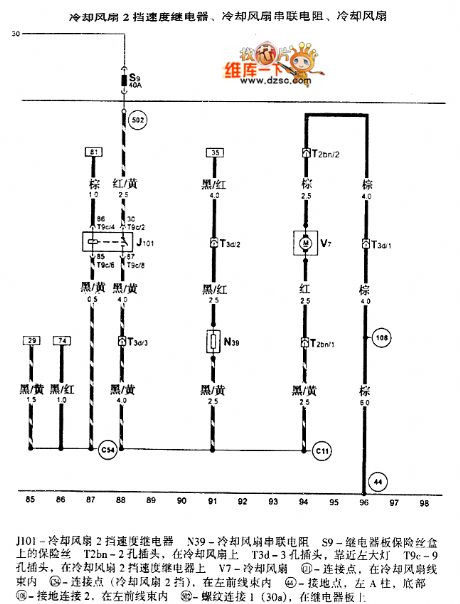
The 2-gear speed relay, serial resistor and circuit of the Golf cooling fan is shown as above.J101-the cooling fan 2-gear speed relay N39-the cooling fan serial resistorS9-the fuse on the relay plate box T2bn-2-hole plug, on the cooling fan T3d-3-hole plug, near the large lamp T9c-9-hole plug, on the 2-gear speed relay of the cooling fan V7-the cooling fan C11-connector, in the wire bundle of the cooling fan C54-connector (2nd gear of the cooling fan), in the left-front wire bundle 44-ground connector, left A pillar, on the bottom (View)
View full Circuit Diagram | Comments | Reading(771)
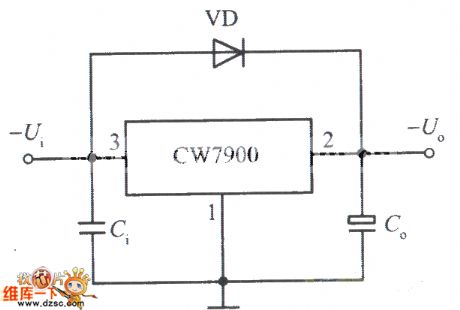
Fixed negative output integrated voltage stabilizer circuit with the input port short-circuit protection function
Published:2011/7/6 21:38:00 Author:Christina | Keyword: Fixed, negative output, integrated voltage stabilizer, input port, short-circuit protection
View full Circuit Diagram | Comments | Reading(736)
Bora dashboard, turning indicator light and headlight circuit
Published:2011/7/6 21:50:00 Author:Christina | Keyword: Bora, dashboard, turning indicator light, headlight
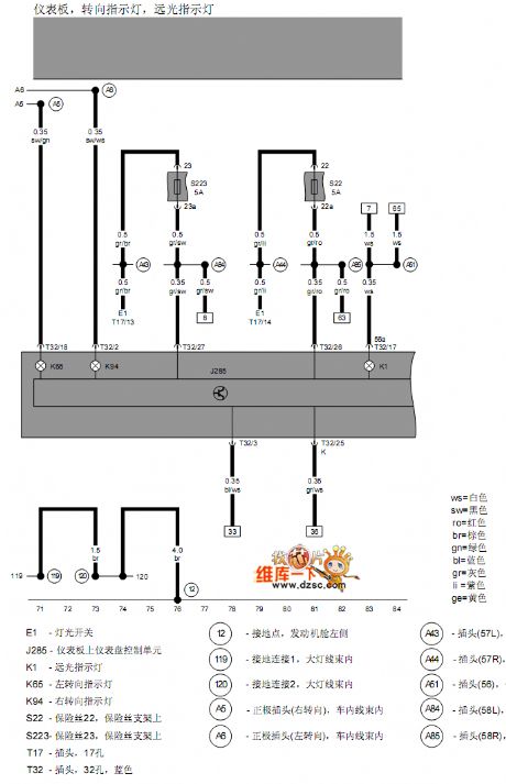
The Bora dashboard, turning indicator light and headlight circuit is as shown in the figure:
(View)
View full Circuit Diagram | Comments | Reading(567)
SPT1141/1151 multi-function switch controller typical application circuit
Published:2011/7/6 21:54:00 Author:Christina | Keyword: multi-function, switch controller, typical application
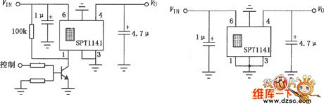
Figure: SPT1141/1151 multi-function switch controller typical application circuit
(View)
View full Circuit Diagram | Comments | Reading(580)
Bora right side gas discharge lamp, right headlight, right parking lamp and right steering lamp circuit
Published:2011/7/7 1:55:00 Author:Christina | Keyword: Bora, right side, gas discharge lamp, right headlight, right parking lamp, right steering lamp
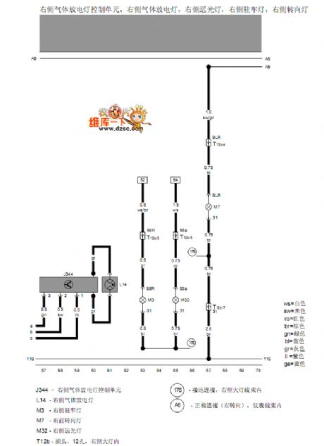
The Bora right side gas discharge lamp, right headlight, right parking lamp and right steering lamp circuit is as shown in the figure:
(View)
View full Circuit Diagram | Comments | Reading(521)
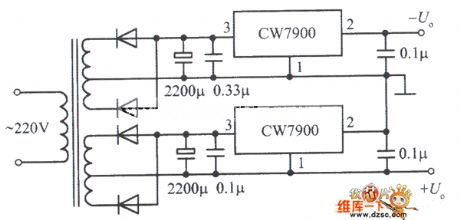
Positive and negative output voltage integrated voltage stabilization power supply circuit
Published:2011/7/7 1:58:00 Author:Christina | Keyword: Positive, negative, output voltage, integrated, voltage stabilization, power supply
View full Circuit Diagram | Comments | Reading(662)
The timing alarm circuit composed of 5G26
Published:2011/7/7 21:04:00 Author:Seven | Keyword: timing alarm
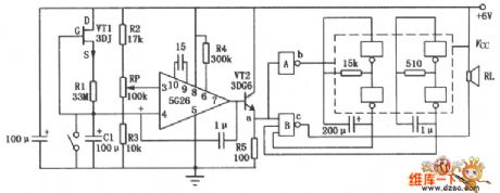
In the figure is the timing alarm circuit composed of integrated computing amplifier 5G26 and the NAND. The left part of the circuit is a timing device, 5G26 composes the comparing amplifier circuit, VT1 and R1 compose a constant current source, which charges C1, and the LEV of Vc is rising gradually (non-inverting phase input of the integrated op-amp), the RP potentiometer adjusts the voltage on the inverting input terminal, by comparing the non-inverting or inverting input LEV, RP decides whether to output a high or low LEV. The right part and NAND are as the voltage control.
(View)
View full Circuit Diagram | Comments | Reading(587)
Single-chip microcomputer fryer control circuit
Published:2011/7/7 2:00:00 Author:Christina | Keyword: Single-chip microcomputer, fryer, control circuit
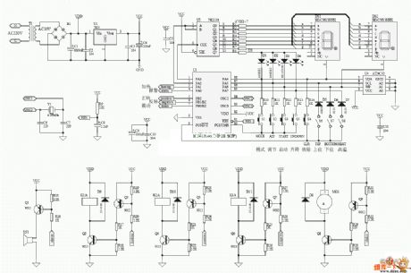
The Single-chip microcomputer fryer control circuit is as showni in the figure:
(View)
View full Circuit Diagram | Comments | Reading(699)
Bora right side headlamps adjustment motor circuit
Published:2011/7/7 2:01:00 Author:Christina | Keyword: Bora, right side, headlamps, adjustment motor
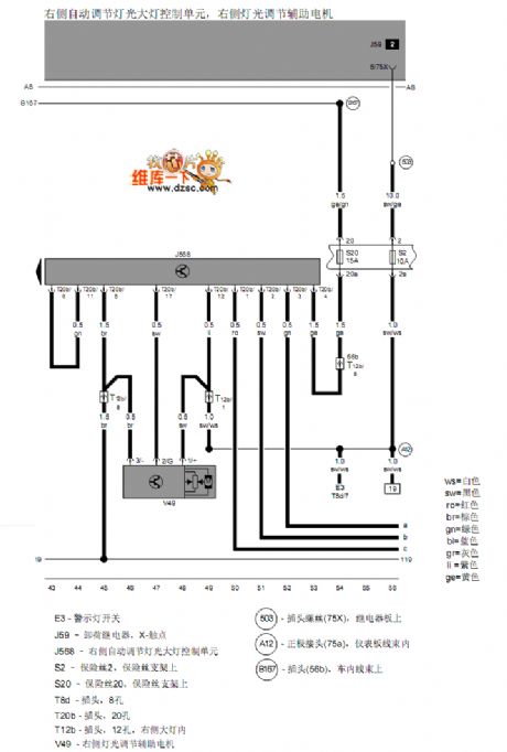
The Bora right side headlamps adjustment motor circuit is as shown in the figure:
(View)
View full Circuit Diagram | Comments | Reading(511)
The simple fade out/in switch circuit
Published:2011/7/7 20:54:00 Author:Seven | Keyword: fade out/in
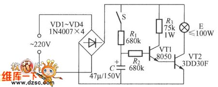
The simple fade out/in switch circuit is shown in the figure, usually, the switch S is open, triodes VT1 and VT2 are both blocked, the lamp E is not glowing. When we need the lamp to light, just close S, the 220V AC current is turned into an impulse DC current after rectification, the capacitor C is charged by switch S and resistor R, which makes the voltage on C rise. Therefore, VT1 can acquire rising basic bias current through R2, so VT1 and VT2 are both turn into the amplifying state from the blocked, finally, they are fully conducted.
(View)
View full Circuit Diagram | Comments | Reading(1833)
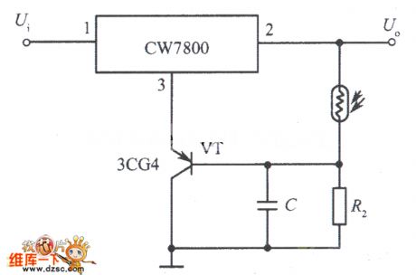
Light control integrated voltage stabilization power supply circuit (2)
Published:2011/7/7 2:03:00 Author:Christina | Keyword: Light control, integrated voltage stabilization, power supply circuit
View full Circuit Diagram | Comments | Reading(579)
Temperature measurement circuit composed of the AD7714 and Pt100
Published:2011/7/7 2:11:00 Author:Christina | Keyword: Temperature measurement
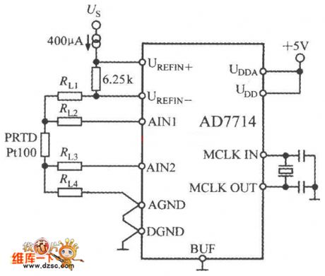
The temperature measurement circuit which is composed of the AD7714 and Pt100 is as shown in the figure. The Pt100 uses the 4-wire connection method, this method can eliminate the voltage drop of the lead resistances RL3 and RL2. The external 400μA current source supplies the PT100 excitation current, and this current produces the reference voltage of AD7714 through the 6.25kΩ resistance. Because the change of input voltage and the reference voltage is proportional to the change of the excitation current. so the change of excitation current will not affect the measurement precision. In order to avoid the influence of the temperature change, the 6.25kΩ resistance need to use the low temperature coefficient metal film resistance.
(View)
View full Circuit Diagram | Comments | Reading(13554)
YDS100/200 switching power supply integrated circuit
Published:2011/7/7 2:53:00 Author:Christina | Keyword: switching power supply, integrated circuit
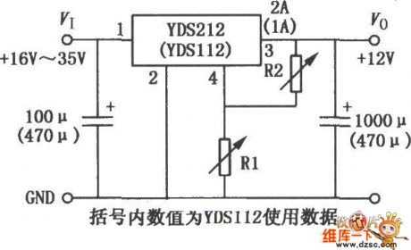
Figure:YDS100/200 switching power supply integrated circuit
(View)
View full Circuit Diagram | Comments | Reading(701)
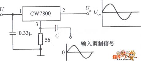
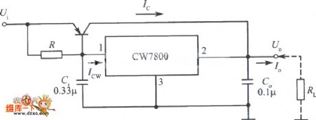
Power modulator circuit composed of the integrated voltage stabilizer CW7800
Published:2011/7/7 2:56:00 Author:Christina | Keyword: Power modulator, integrated voltage stabilizer
View full Circuit Diagram | Comments | Reading(558)
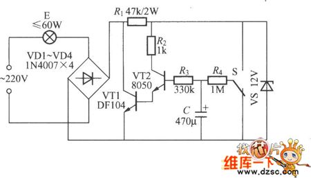
The light control electric switch circuit
Published:2011/7/7 20:32:00 Author:Seven | Keyword: light control, electric switch
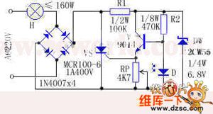
The ON and OFF of the light control electric switch is completed by the conduction or block of SCR, and SCR is under control of the brightness of the natural light (or man-made light). This device is fit for the street, the dorm corridor and other public places, which can make lamps light at daytime and put out at night, so the power is saved. Working principle: see as the figure, the 220V AC is past the bulb and rectified in full bridge, after that, it becomes a DC impulse voltage as the forward bias voltage.
(View)
View full Circuit Diagram | Comments | Reading(650)
Typical application circuit of the LM/LT multi-functional switch integrated regulator
Published:2011/7/7 3:10:00 Author:Christina | Keyword: Typical application, LM/LT, multi-functional, switch, integrated regulator
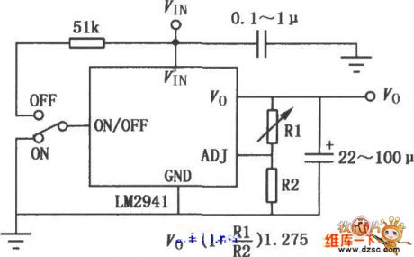
Figure:Typical application circuit of the LM/LT multi-functional switch integrated regulator
(View)
View full Circuit Diagram | Comments | Reading(709)
Bora left headlight regulation and control unit, right headlight regulation and control unit circuit
Published:2011/7/7 3:11:00 Author:Christina | Keyword: Bora, left headlight, regulation, control unit, right headlight
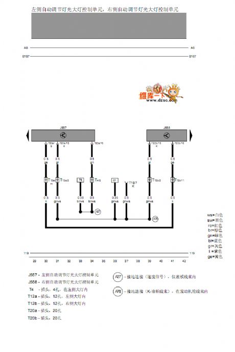
Bora left headlight regulation and control unit, right headlight regulation and control unit circuit
(View)
View full Circuit Diagram | Comments | Reading(456)
Large current output integrated voltage stabilization power supply circuit (1)
Published:2011/7/7 3:13:00 Author:Christina | Keyword: Large current, output, integrated voltage stabilization, power supply
View full Circuit Diagram | Comments | Reading(524)
RMS level measuring instrument circuit composed of the AD8362
Published:2011/7/7 3:24:00 Author:Christina | Keyword: RMS level, measuring instrument
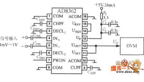
The RMS level measuring instrument circuit which is composed of the AD8362 is as shown in the figure, the output voltage of AD8362 is added to the digital voltmeter (DVM) directly. You should notice that the reading of DVM is proportional with the logarithm of the measured RMS voltage, so it is the voltage level measuring instrument, the display unit is dBv. When you are measuring the radio-frequency signal with high input frequency, you must use the measures as follow: the first is that you need to add the decoupling capacitor to the input port, the second is that you need to shorten the length of the input signal leads, the decoupling capacitor leads and the ground leads. The decoupling network of the +5V power supply is composed of the R1, C1 and C2.
(View)
View full Circuit Diagram | Comments | Reading(773)
| Pages:1593/2234 At 2015811582158315841585158615871588158915901591159215931594159515961597159815991600Under 20 |
Circuit Categories
power supply circuit
Amplifier Circuit
Basic Circuit
LED and Light Circuit
Sensor Circuit
Signal Processing
Electrical Equipment Circuit
Control Circuit
Remote Control Circuit
A/D-D/A Converter Circuit
Audio Circuit
Measuring and Test Circuit
Communication Circuit
Computer-Related Circuit
555 Circuit
Automotive Circuit
Repairing Circuit