
Circuit Diagram
Index 1597
The infrared sensor security device circuit
Published:2011/7/6 22:52:00 Author:qqtang | Keyword: infrared sensor, security device

See as the circuit, it consists of the infrared sensor control circuit, relay control circuit, music generating circuit and so on, which can be used in infrared alarm, timing control and other spots. (View)
View full Circuit Diagram | Comments | Reading(1929)
The infrared sensor security device circuit (2)
Published:2011/7/6 22:58:00 Author:qqtang | Keyword: infrared sensor, security device
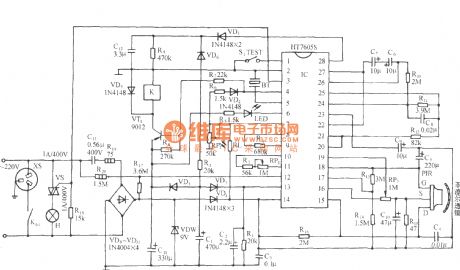
The figured circuit is assembled on the base of HT-7605 integrated circuit, whose power supply is AC step-down rectifier circuit, and its output control can be the SCR or relay, it can also fulfill multiple operation functions. (View)
View full Circuit Diagram | Comments | Reading(883)
The ultra-sonic wave receiver circuit of distance detection
Published:2011/7/6 23:18:00 Author:qqtang | Keyword: ultra-sonic wave, receiver circuit
The working voltage of the circuit is 9V, and its current is only 5mA, its frequency is in the range of 150~180kHz, the band width is about 20kHz, which make sure that only the pulses whose band width is over 70μs is passable and amplified. The input terminal of the receiver is directly connected with the sensor, i.e it is connected with the oscillator. When the ultra-sonic wave signal appears, the signal voltage on the basic pole of T1 is limited to a low value by the diodes D1 and D2. The transistors T1 and T5 compose the 2 stage high frequency amplifier, and then the pulse is rectified by D3.
(View)
View full Circuit Diagram | Comments | Reading(797)
The 4-channel ultra-sonic wave generator circuit of the projector
Published:2011/7/7 0:01:00 Author:qqtang | Keyword: 4-channel, ultra-sonic wave generator
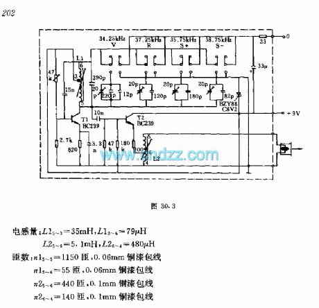
To remote control the projector, we often need 4 channel signals of different frequencies, i.e forward, backward, focus ahead focus backward, at the moment, the figured emitting circuit can be used. In the circuit, the oscillator consists of the transistor T, when the inductance L1 is stable, it is linked to different capacitors and generates signals of different frequencies. The figured V means forward, S means backward, S+ and S- mean focus ahead and focus backward respectively.
(View)
View full Circuit Diagram | Comments | Reading(966)
Fluorescent Lamp Electronic Ballast (2)
Published:2011/7/5 21:37:00 Author:Sue | Keyword: Fluorescent Lamp, Electronic, Ballast

The 220V voltage will provide the push-pull oscillate circuit with 280-300V working voltage after it is rectificated by VD3-VD6, filtrated by T1, soothing filtrated.
When the power is on, the pulse current will heat the fluorescent lamp ty C4,V7. When the push-pull oscillate circuit begins to work, C7's voltage reaches EL's discharge voltage. EL is illuminated. (View)
View full Circuit Diagram | Comments | Reading(7689)
Wound rotor induction motor serial resistor step-down start-up circuit
Published:2011/7/6 9:13:00 Author:John | Keyword: Wound rotor, induction motor, serial resistor, 3KT
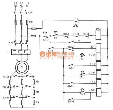
The circuit is as shown. Three time relays 1KT, 2KT and 3KT are used to automatically remove the rotor windings with three resistors of 1R, 2R and 3R. As a result, the purpose of automatically started to run has been achieved.
(View)
View full Circuit Diagram | Comments | Reading(2726)
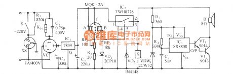
greenhouse flower nursery humidity control with bird voice alarming circuit MS01-B
Published:2011/7/6 9:12:00 Author:John | Keyword: bird voice, greenhouse flower
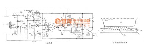
The circuit is shown, which consists of humidity sensor, detection circuit, temperature indicator, comparator circuit, SCR control heating circuit, bird voice circuit and exchanging buck rectifier circuit. RH is the humidity sensor, which uses the MS01-B type. When the relative humidity inside the greenhouse changes from 20% to 90%, its resistance can range with a few kΩ to hundreds of kΩ.
(View)
View full Circuit Diagram | Comments | Reading(1053)
PWM micro-motor speed control circuit
Published:2011/7/6 9:12:00 Author:John | Keyword: micro-motor, PWM
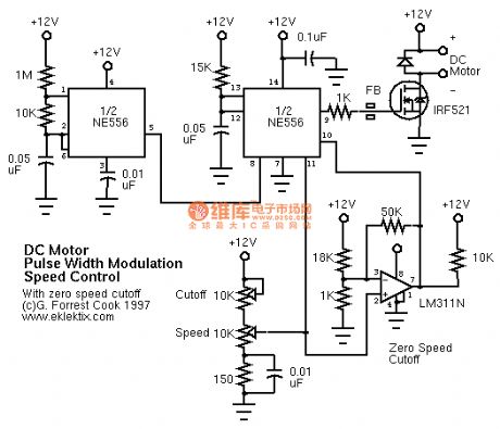
View full Circuit Diagram | Comments | Reading(1607)
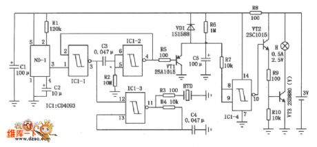
Gas leak sound and light alarming and auto exhausting device circuit
Published:2011/7/6 9:11:00 Author:John | Keyword: Gas leak, sound and light alarming, auto exhaust device
The circuit is as shown. It consists of the gas sensor, the relay exhaust fan control circuit, sound and light alarming circuit and AC buck rectifier circuit.
(View)
View full Circuit Diagram | Comments | Reading(755)
Gas leak automatic language alarming circuit
Published:2011/7/6 9:10:00 Author:John | Keyword: Gas, automatic language alarming, Gas leak
The circuit is as shown. It consists of the gas detection sensor, power switching control circuit, language voiced circuit and communication buck rectifier circuit. When the gas leak in the kitchen or living room reaches a certain concentration, the circuit will automatically start to exhaust through the exhaust fan. When the fan is started, a sentence said check for gas leak would be stated to warn the owner to pay attention to safety.
(View)
View full Circuit Diagram | Comments | Reading(996)
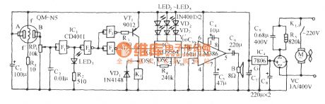
Vehicle vibration alarm circuit
Published:2011/7/4 0:50:00 Author:John | Keyword: Vehicle
Vehicle vibration alarm circuit is shown. As for the circuit, ND-1 is the vibration sensor, which can be used to detect the state of the vehicle. When the car is hit, affected, lift, shaken, vibrations will be detected and control signals will be output. IC1 is the non-gate IC CD4093 with the four ends of Schmitt Trigger. It combines the non-gate IC1-1 and IC1-2 to form the l-second timer. It also combines the non-gate IC1-3 to form the low-frequency oscillator. When the vibration sensor ND-1 detects the vibration signal, it generates control signals to drive the l-second timer and low-frequency oscillator to work. Therefore, the piezoelectric ceramics HTD alarms. (View)
View full Circuit Diagram | Comments | Reading(1385)
Basic mixer - LO circuit
Published:2011/7/4 0:43:00 Author:John | Keyword: Basic mixer
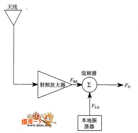
Direct conversion receiver and the superheterodyne receiver are similar to some basic concepts. The RF signal received by the receiver is the nonlinear mixed signal, which is based on its own frequency and local oscillator’s (LO) oscillation signal. It means the heterodyning transfer. Figure shows two basic functional block circuit which are receiving the front-end circuit. Mixer shown in the figure is a nonlinear element, which is used to mix two signals from FRF and F. Output signal from the mixer contains different frequency components, which is required to meet the following relationship:
(View)
View full Circuit Diagram | Comments | Reading(648)
parallel oscillation circuit in radio receiver
Published:2011/7/4 0:29:00 Author:John | Keyword: Radio receiver
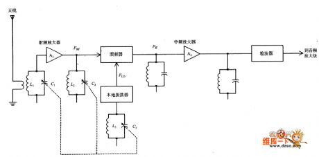
Radio receiver's parallel oscillation circuit is shown.
(View)
View full Circuit Diagram | Comments | Reading(537)
Campbell passive duplex filter circuit
Published:2011/7/4 0:42:00 Author:John | Keyword: passive duplex filter
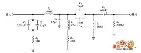
Campbell's paper gives the author another digital wonders example. That is, the achievement of a functional digital circuit is always superior to the implementation of an analog circuit. He points out that IC filter’s dynamic range depends on the inductance. The bottom of the dynamic range is the thermal noise current (4KTBR) caused by the circuit’s resistance. The top of the dynamic range depends on saturation current of the inductor core. The dynamic range of Campbell’s selected component is up to 180dB. In comparison, the expensive 24-bit audio A / D converter only has 144dB on dynamic range.
(View)
View full Circuit Diagram | Comments | Reading(1053)
SSB modulator based on LM-1496 circuit
Published:2011/7/4 0:29:00 Author:John | Keyword: SSB modulator
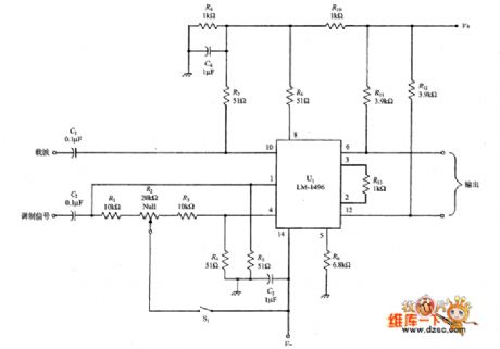
The picture shows the double-sideband suppressed-carrier (DSBSC) signal circuit generated by the LM-1496. When it is followed by connecting the IF-stage with the band-pass filter of the band 2.5 ~ 3kHz, the circuit can also produce single-sideband signal. Usually,carrier signal Vcis generated by a crystal generates and the audio level generates modulated signals Vm through microphone input end or the audio oscillator. J. Carl • Yoshev has ever seen a circuit which is just like a signal generator / test equipment. This circuit can be used for amateur radio and the Navy HF-SSB’s radio transceiver.
(View)
View full Circuit Diagram | Comments | Reading(5396)
QS6M3 internal circuit
Published:2011/7/6 9:07:00 Author:John | Keyword: internal circuit
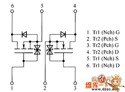
View full Circuit Diagram | Comments | Reading(588)
lock control intelligent anti-theft with TX982 circuit
Published:2011/7/4 0:47:00 Author:John
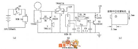
Lock control intelligent anti-theft with TX982 circuit is the lock intelligent alarm control unit designed for balcony’s anti-theft, just as shown in the figure. When the owner is out, the circuit automatically turns in to the alert state and the remote doorbell expires automatically. It isable to prevent the thief to sound out whether anyone at home through the bell If the thief climbed up the balcony for burglary, the circuit will immediately send an alarm up to 120dB sound rapidly. Therefore, the thief fears to escape quickly. Figure (a) shows a transmitter, which is installed at the gate. And figure (b) shows a receiving circuit, which is installed in the balcony’s ceiling.
(View)
View full Circuit Diagram | Comments | Reading(615)
Southeast Freeca lighting system circuit
Published:2011/7/4 0:46:00 Author:John | Keyword: lighting system
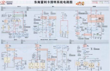
View full Circuit Diagram | Comments | Reading(805)
Fluorescent Lamp Electronic Ballast (1)
Published:2011/7/5 21:44:00 Author:Sue | Keyword: Fluorescent Lamp, Electronic, Ballast
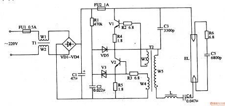
When the power is on, the ac 220V voltage will provide the high-frequency oscillator with 280V working voltage after it is rectificated by VD1-VD4, filtrated by C1,C2.Transistor V1, V2 will begin to oscillate with a high frequency under the influence ofthe capacitor C3,C4,C6-C10 and T's winding W1-W3. There will be a high frequent voltage similar to sinusoidal waveform between A and B and the voltage will illuminate EL1 and E after it is put on filaments of EL1,EL2 by L1,C7-C10. (View)
View full Circuit Diagram | Comments | Reading(4161)
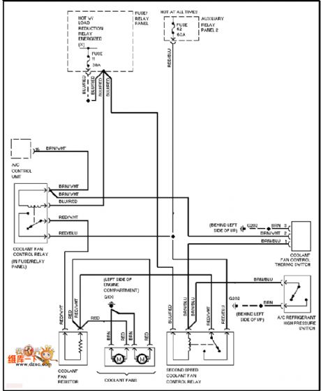
Audi air conditioning fan circuit
Published:2011/7/4 0:46:00 Author:John | Keyword: air conditioning fan
View full Circuit Diagram | Comments | Reading(830)
| Pages:1597/2234 At 2015811582158315841585158615871588158915901591159215931594159515961597159815991600Under 20 |
Circuit Categories
power supply circuit
Amplifier Circuit
Basic Circuit
LED and Light Circuit
Sensor Circuit
Signal Processing
Electrical Equipment Circuit
Control Circuit
Remote Control Circuit
A/D-D/A Converter Circuit
Audio Circuit
Measuring and Test Circuit
Communication Circuit
Computer-Related Circuit
555 Circuit
Automotive Circuit
Repairing Circuit