
Circuit Diagram
Index 1594
The dual-way control SCR liquid level control circuit
Published:2011/7/7 20:24:00 Author:Seven | Keyword: dual-way control, liquid level
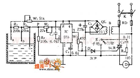
See as the figure, the controller consists of liquid level, trigger controller and step-down rectifier circuit, etc. The water level detecting poles of a, b and c compose the bias circuit as the water level detector with W1, R1, R2 and R3. When the water level is below b , Vp-b≈R3×VDD/(Rw1+R1+R2+R3)<1/3VDD, 555 is offset, SCR is triggered and conducting, the motor is running and drawing water. When the level is over a , Vp-a≈R3×VDD/(Rw1十R3)>2/3VDD, so 555 is reset, 3-pin is in a low LEV, SCR is blocked and the motor stops. (View)
View full Circuit Diagram | Comments | Reading(2917)
Bora left headlight regulation and control unit, regulation motor and vehicle level sensor circuit
Published:2011/7/7 3:29:00 Author:Christina | Keyword: Bora, left headlight, regulation, control unit, regulation motor, vehicle level sensor
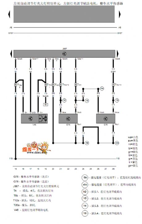
The Bora left headlight regulation and control unit, regulation motor and vehicle level sensor circuit:
(View)
View full Circuit Diagram | Comments | Reading(512)
Pressure measurement system composed of the AD7714
Published:2011/7/7 3:39:00 Author:Christina | Keyword: Pressure, measurement system
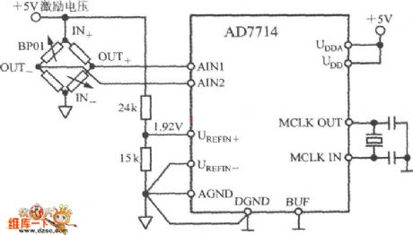
The pressure measurement system which is composed of the AD7714 is as shown in the figure. The BP01 is designed as the pressure sensor which is produced by the Sensym company. You need to connect the BP01 into the bridge circuit, the OUT+ and OUT- ports output the differential voltage. If you add the rated full scale pressure on the pressure sensor, the sensitivity of the differential output voltage is 3mV/V. If you use the +5V excitation voltage, the full-scale output range of the sensor is ±15mV. This excitation voltage is divided by the 24kΩ and 15kΩ resistances to supply the 1.92V benchmark voltage for the AD7714, so the fluctuation of the excitation voltage will not cause the measurement error.
(View)
View full Circuit Diagram | Comments | Reading(757)
Bora left gas discharging lamp, left headlight, left parking light and left steering lamp circuit
Published:2011/7/7 3:51:00 Author:Christina | Keyword: Bora, left gas discharging lamp, left headlight, left parking light, left steering lamp
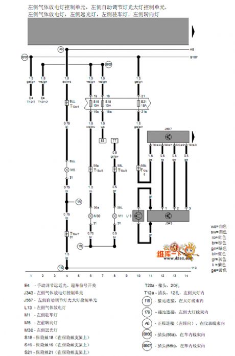
Bora left gas discharging lamp, left headlight, left parking light and left steering lamp circuit
(View)
View full Circuit Diagram | Comments | Reading(637)
TOP22-227 principle circuit
Published:2011/7/7 20:18:00 Author:Christina | Keyword: principle
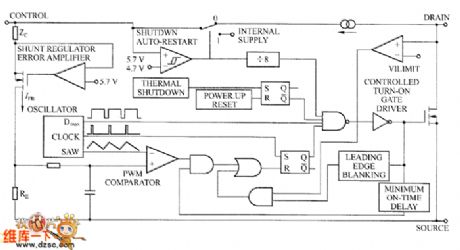
Set the TOP smart power switch as the example, the principle circuit of the TOP22X series devices are as shown in the figure. The TOP22X switch only has three leads, in addition to the drain lead and the feedback control lead of the power switch, there is a feedback control lead. The operating frequency is 100 kHz, the operating mode is the voltage type PWM. The output voltage is detected, compared and amplified, then it changes into the current signal and adds to the feedback control lead, the internal RE resistance changes the current signal into the voltage signal to compare with the triangular wave, so it changes the pulse width to realize PWM modulation.
TOP22-227 principle circuit (View)
View full Circuit Diagram | Comments | Reading(624)
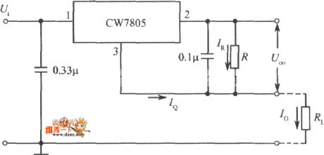
Constant current source circuit composed of the three-port fixed output integrated regulator
Published:2011/7/7 3:53:00 Author:Christina | Keyword: Constant current, source, three-port, fixed, output integrated regulator
View full Circuit Diagram | Comments | Reading(764)
Panasonic NA1900 washing machine circuit
Published:2011/7/7 20:20:00 Author:Christina | Keyword: Panasonic, washing machine
The Panasonic NA1900 washing machine circuit is as shown in the figure:
(View)
View full Circuit Diagram | Comments | Reading(4852)
High input-high output integrated voltage stabilization power supply circuit (1)
Published:2011/7/7 20:22:00 Author:Christina | Keyword: High input, high output, integrated, voltage stabilization, power supply
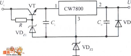
View full Circuit Diagram | Comments | Reading(570)
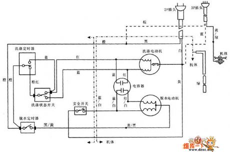
Xiaoshentong XQB20-A washing machine circuit principle diagram
Published:2011/7/7 20:25:00 Author:Christina | Keyword: Xiaoshentong, XQB20-A, washing machine, principle diagram
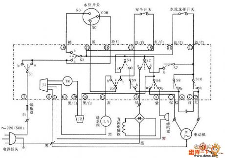
The Xiaoshentong XQB20-A washing machine circuit principle diagram is as shown in the figure:
(View)
View full Circuit Diagram | Comments | Reading(913)
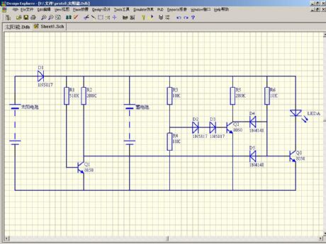
Solar energy lamp circuit
Published:2011/7/4 22:14:00 Author:zj | Keyword: Solar energy, lamp circuit
View full Circuit Diagram | Comments | Reading(1282)
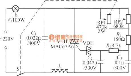
Practical bidirectional thyristor dimmer lamp circuit
Published:2011/7/6 21:20:00 Author:zj | Keyword: Practical, bidirectional thyristor, dimmer lamp circuit
View full Circuit Diagram | Comments | Reading(856)
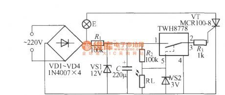
Light control street lamp circuit using TWH8778 (2)
Published:2011/7/7 22:23:00 Author:zj | Keyword: Light control, street lamp circuit, using TWH8778
View full Circuit Diagram | Comments | Reading(644)
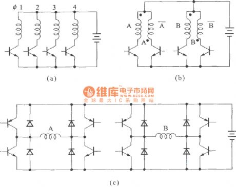
The step motor drive circuit and its drawing
Published:2011/7/7 7:50:00 Author:Seven | Keyword: step motor, drive circuit
View full Circuit Diagram | Comments | Reading(654)
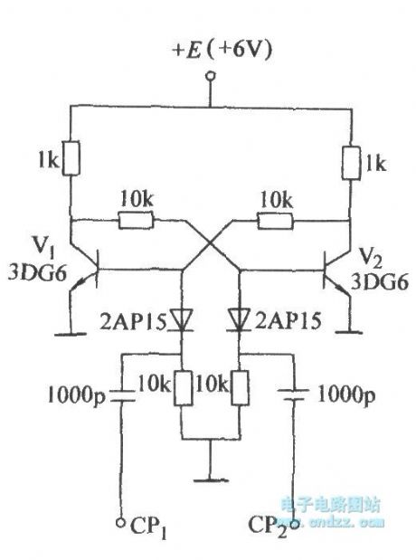
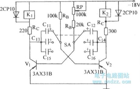
The transformative emitter coupling dual steady circuit
Published:2011/7/7 7:52:00 Author:Seven | Keyword: transformative emitter, dual steady circuit
View full Circuit Diagram | Comments | Reading(613)
The double steady circuit without reversed bias
Published:2011/7/7 7:54:00 Author:Seven | Keyword: double steady circuit, reversed bias
View full Circuit Diagram | Comments | Reading(655)
The sound source switch circuit composed of SCR
Published:2011/7/7 8:04:00 Author:Seven | Keyword: sound source, switch circuit
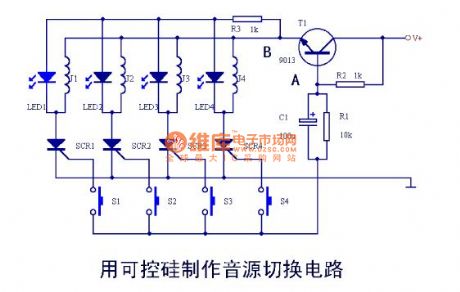
When the power is getting through, as the control pole of SCR1--SCR4 has no trigger current, so it is in the turn-off state, none of J1-J4 is taking action. If J1 pulls in, by pressing S1, the current will charges C1 through R2, point A is in a low LEV to the earth, T1 is blocked. As C1 is charged, the LEV of B is rising with the LEV of A. At that moment, the charge current of C1 is crossing the control of SCR1, so SCR is conducting, J1 is getting power and pulling in, LED1 is glowing, after S1 is released, as the effect of SCR1, J1 remains the same, C1 is discharging through R1. (View)
View full Circuit Diagram | Comments | Reading(748)
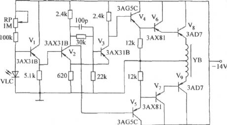
The audio control and soft switch amplifier
Published:2011/7/7 8:07:00 Author:Seven | Keyword: audio control, soft switch amplifier
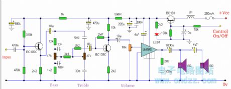
The soft switching is enabled by a BD131 transistor wired as a switch in emitter follower configuration. The collector is wired to a permanent supply voltage, the 2H series inductor serves only to filter out power supply hum. This inductor is not too important and may be omitted if the DC supply is adequately smoothed. The control voltage is applied to the BD131 base terminal, the 10u capacitor and 10k resistor having a dual purpose:-i) a gradual charge of the 10u capacitor ensures that the transistor will switch linearly from 0 volts to full supply, andii) serves as a hum filter ensuring a very smooth dc supply to the amplifier and tone controls.LED1 will light when the amplifier is on. The control voltage should ideally be 0 volts when the amplifier is off and full supply voltage when on. The LM380 is shown driving two 8 ohm loupspeakers, the load is therefore 4 ohms. The 4u7 capacitor acts as a crude crossover, lower frequencies are impeded and so this loudspeaker may be a tweeter type. (View)
View full Circuit Diagram | Comments | Reading(1011)
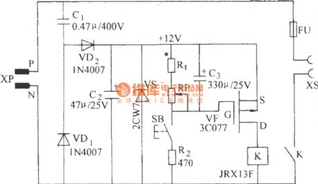
The time delay circuit with a FET
Published:2011/7/7 8:09:00 Author:Seven | Keyword: time delay circuit, FET
View full Circuit Diagram | Comments | Reading(740)
The astable circuit of direct relay drive
Published:2011/7/7 8:11:00 Author:Seven | Keyword: astable circuit, relay drive
View full Circuit Diagram | Comments | Reading(814)
The over-current precaution circuit (current limiting circuit)
Published:2011/7/7 8:27:00 Author:Seven | Keyword: over-current precaution
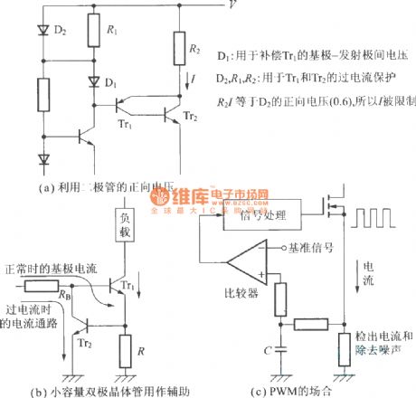
D1 is used to compensate the voltage between the base-electrode of Tr1; D2, R1 and R2 are used for over-current protection of Tr1 and Tr2; R2I is equal to the forward voltage(0.6) of D2, so it is limited.(a) the forward voltage of the diode in use(b) small volume diode as the assistance(c) the PWM spot (View)
View full Circuit Diagram | Comments | Reading(908)
| Pages:1594/2234 At 2015811582158315841585158615871588158915901591159215931594159515961597159815991600Under 20 |
Circuit Categories
power supply circuit
Amplifier Circuit
Basic Circuit
LED and Light Circuit
Sensor Circuit
Signal Processing
Electrical Equipment Circuit
Control Circuit
Remote Control Circuit
A/D-D/A Converter Circuit
Audio Circuit
Measuring and Test Circuit
Communication Circuit
Computer-Related Circuit
555 Circuit
Automotive Circuit
Repairing Circuit