
Circuit Diagram
Index 1584
Three-phase motor braking circuit 1
Published:2011/7/8 22:14:00 Author:Lucas | Keyword: Three-phase motor, braking
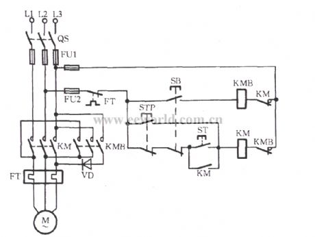
The circuit shown as chart is a simpledynamic braking circuit with addingan AC contactor KMB and rectifier diode VDon the basic ofthe original magnetic starter KM.
(View)
View full Circuit Diagram | Comments | Reading(4232)
Three-phase motor winding reverse connection check circuit
Published:2011/7/10 2:19:00 Author:Lucas | Keyword: Three-phase motor , winding reverse connection, check circuit
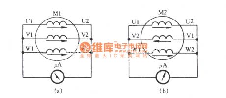
Three-phase motor winding or a coil is embedded reversely, due to the direction of winding current flowing changes reversely, it will cause three-phase motor vibration, noise, and a serious imbalance in three-phase current, motor overheating, speed reducing, and the motor even can not start, and the fuse is blown. In general, one winding is reversed as external leads being connected correctly. Microampere meter block is available for inspection as this time, and the circuit is shown as the chart. When operation, the three-phase windings are connected at the head and tail according to the marks, then turn the three-phase motor rotor by hand, if the table pointer does not move, then the winding head and tail are connected correctly as shown in Figure (a).
(View)
View full Circuit Diagram | Comments | Reading(3022)
Three-phase motor transistor automatic limiting reversing circuit
Published:2011/7/8 6:23:00 Author:Lucas | Keyword: Three-phase, motor , transistor , automatic limiting reversing
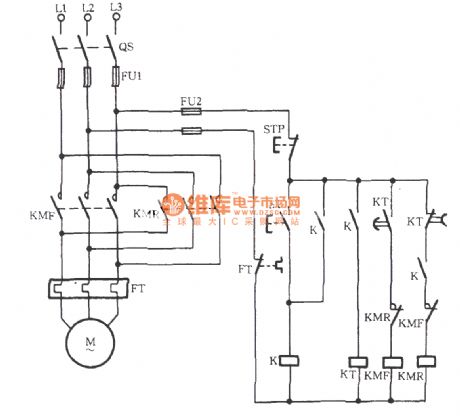
The circuitshown in the chart usestime relay KT, pulse transistor JJSB1, time relay,and ithas normally open, normally closed contacts with adjustable time,ifit is addedtherelay K, the circuit will automatically limit time and operatefrom positive toreverse.
(View)
View full Circuit Diagram | Comments | Reading(1413)
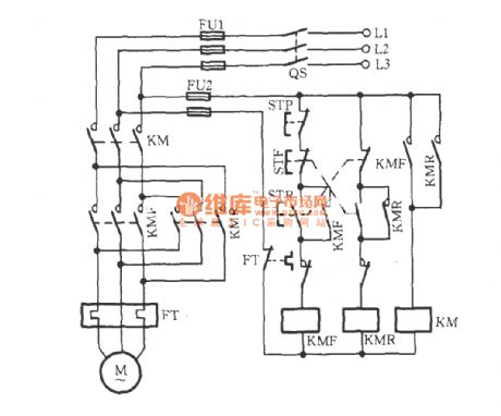
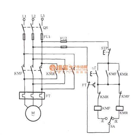
Three-phase motor contactor auxiliary contact interlock switching circuit
Published:2011/7/8 6:33:00 Author:Lucas | Keyword: Three-phase , motor contactor , auxiliary contact , interlock switching
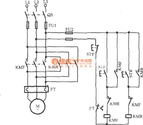
The circuit shown as the chart uses two AC contactors KMF and KMR. KMF is used for forward, KMR is used for reversal. As the main contact wiring phase sequence of AC contactor is different, when the two contacts are at work, the motor turning is opposite. Because of this, the operation dose not allow KMF and KMR to be pulled at the same time. To this point, in the forward and reverse control circuits, each circuit is stringed into the normally closed contact of the other one. Contactor self-protection auxiliary contacts KMF, KMR are increased in the circuit.
(View)
View full Circuit Diagram | Comments | Reading(8410)
Three-phase motor contactor button interlock action for switching circuit
Published:2011/7/9 10:48:00 Author:Lucas | Keyword: Three-phase motor, contactor button, interlock
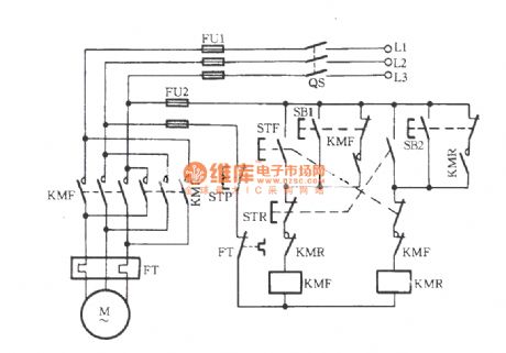
Just shown in the figure, STF, STR, SB1 and SB2 all are composite buttons. STF and STR are respectively positive and reverse button, which operate along with the contactor’s auxiliary contacts for achieve interlock action. SB1 and SB2 both are jog buttons. (View)
View full Circuit Diagram | Comments | Reading(3569)
CXD2309Q-Y, U, V D/A convertor integrated circuit
Published:2011/7/10 5:06:00 Author:leo | Keyword: Y, U, V D/A convertor, 3 based color processing circuit
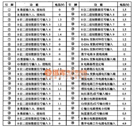
CXD2309Q is a new type of Y, U, V D/A convertor integrated circuit produced by Sony Company which is widely used in smooth big screen, digital television and other big screen color television.
Function features:CXD2309Q contains 3 based color signals D/A convertor, 3 based color processing circuit, 8 bits binary data and processing circuit, 3 based color D/A converting power supply circuit, 3 based color D/A converting signal processing circuit and other related circuits.
Pin functions and data:CXD2309Q uses 48 pins dual line package and its pin functions are shown in the picture 1. (View)
View full Circuit Diagram | Comments | Reading(728)
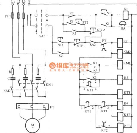
Three-phase motor intermittent starting circuit
Published:2011/7/10 2:29:00 Author:Lucas | Keyword: Three-phase motor
View full Circuit Diagram | Comments | Reading(1169)
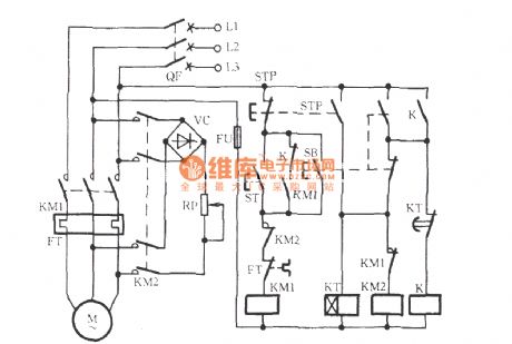
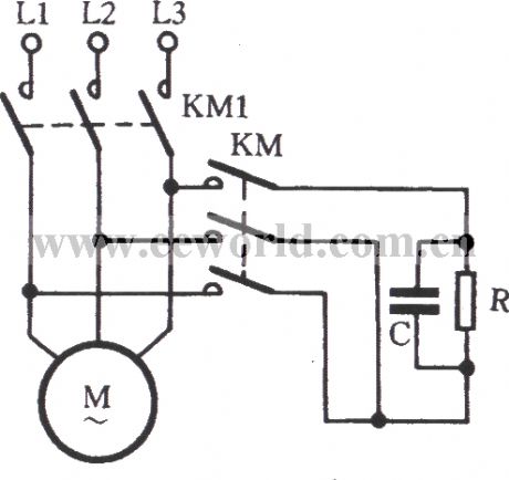
Three-phase motor self-motivation brake circuit
Published:2011/7/10 2:22:00 Author:Lucas | Keyword: Three-phase motor, KM2
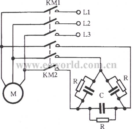
Just as shown in the figure, RC components are connected to stator windings during the free braking so as to form a self-motivation brake circuit. 2KM is closed when the KM1 is off. At this moment, the stator’s remanence induction would generate a capacitive current by RC circuit. It will strengthen the rotor’s remanence magnetic created by its magnetic. The brake torque is formed for braking the motor at high speed. RC circuit’s connection should be done according to the winding connection of the three-phase stator. It is tested that RC with Y connection circuit is suitable for Y-connection motor.
(View)
View full Circuit Diagram | Comments | Reading(2945)
TL494-Pulse width modulation integrated circuit
Published:2011/7/10 4:04:00 Author:leo | Keyword: Pulse width modulation, switch power resource circuit
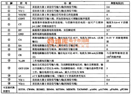
LA4582C is a kind of signal chip stereo player integrated circuit produced by Sanyo Company. It is widely used in all kinds of walk man TL494 is a kind of dedicated double-ended impulse modulation component which can be used to produce double-ended push-pull, half-bridge and full-bridge switch power resource. It is widely used in DVD, VCD, computer system and all kinds of appliance switch power resource circuit.
1.Function features:TA494 contains oscillator, difference amplifier, pulse width comparator and based voltage resource and output circuit.2.Pin functions and data:TA494 uses 16 pin dual line package and its pin functions are shown in the picture 1-1.3. Singal process (View)
View full Circuit Diagram | Comments | Reading(1168)
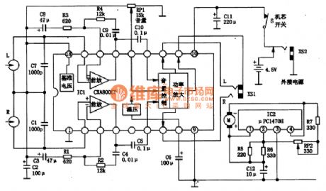
CXA8008P-Single chip player integrated circuit
Published:2011/7/10 5:53:00 Author:leo | Keyword: Single chip, dual channel
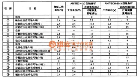
CXA8008P is a kind of single chip player integrated circuit produced by Sony Company. The hot product ANYTECH20 player in the market is made up of this component.
1.CXA8008P inner circuit diagram and pin functions:
CXA8008P is dual channel single chip player circuit. Every channle contains a fronted amplifier, DC volume control circuit and power amplifier. Its inner circuit diagram is shown in the picture 1. This IC uses 18 pin dual line package and its pin functions are shown in the picture 1.
2. CXA8008P classic applying circuits.
Its classic applying circuits are shown in the picture. (View)
View full Circuit Diagram | Comments | Reading(2188)
Simple three-phase motor short braking circuit
Published:2011/7/10 0:25:00 Author:Lucas | Keyword: three-phase motor, KM1
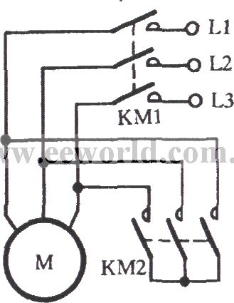
The stator windings maintain the opening state at this moment. The EMF does not produce current and dose not produce braking torque. Thus it is called free brake. If the stator winding is disconnected from the grid as shown in the figure and is short connection by KM2, the remanence potential of the stator windings can be generated to produce current. And the resulting braking effect is called short brake”. When the 5.5kW motor short-circuit brakes, short-circuit current is with duration of 100 milliseconds. It is better than free braking, whose braking time is 3 / 4 of the free braking time.
(View)
View full Circuit Diagram | Comments | Reading(1647)
Three-phase motor for jog brake circuit(b)
Published:2011/7/10 1:18:00 Author:Lucas | Keyword: Three-phase motor, jog brake
View full Circuit Diagram | Comments | Reading(2234)
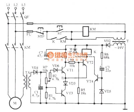
Three-phase motor phase-off protection circuit
Published:2011/7/10 1:21:00 Author:Lucas | Keyword: VD1, Three-phase motor
View full Circuit Diagram | Comments | Reading(998)
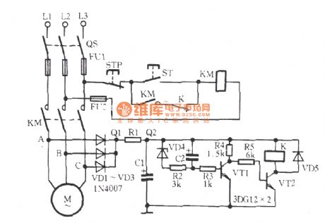
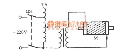
Three-phase motor phase-off over-current protection circuit
Published:2011/7/10 1:36:00 Author:Lucas | Keyword: VD5, Three-phase motor
The figure shows a rather practical circuit. When ST is pressed, KM pulls to start the motor M. The current transformer TA output current through the secondary side. The current forms a voltage signal through the VD1 rectifier and partial pressure by RP and R1. The voltage signal is added to the base VT1 through R2 and VD6. The other signal VT3 added to the base through RP. VT1, VT2 and VT3 form an emitter coupled bitable circuit. During the normal operation, VT1 ends and VT2 and VT3 are saturated to conduct. Then the relay K pulls to drive the motor M to run normally.
(View)
View full Circuit Diagram | Comments | Reading(3129)
Three-phase motor for against phase-phase short circuit commutation circuit
Published:2011/7/10 1:57:00 Author:Lucas | Keyword: Three-phase motor, phase-phase short circuit
During the revering of the motor, the contactor’s main contacts may cause rather serious arcing phenomenon due to operation or for some other reasons. If the arc has not been completely extinguished, the reverse AC contactor pulls to cause phase-phase short circuit. Just as shown in the circuit, an AC contactor KM is used to solve the phase-phase short circuit. During the reversing process of positive and negative, the forward contactor KMF powers off. And the contactor KM (that is the additional one) also disconnect. Therefore, four break interrupters are created. It can effectively extinguish the arc and avoid the phase-phase short circuit failure.
(View)
View full Circuit Diagram | Comments | Reading(1038)
Three-phase motor used for asynchronous generator load distribution circuit
Published:2011/7/10 2:04:00 Author:Lucas | Keyword: 2QS2, Three-phase motor, asynchronous generator
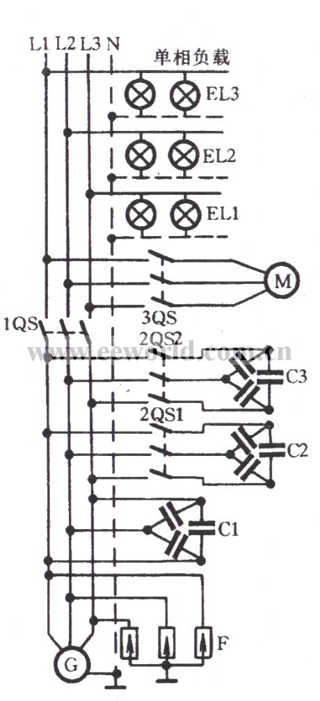
The figure shows the circuit which is applied to distribute the load with small capacity. At this moment, the main capacitor C1, auxiliary capacitor C2 and compensation capacitor C3 are installed on the power distribution screen of the induction generator. The screen is also equipped with lightning protection and over-voltage device. That is the surge arrester.
(View)
View full Circuit Diagram | Comments | Reading(1218)
Three-phase motor with pre-selection switch commutation circuit
Published:2011/7/10 2:10:00 Author:Lucas | Keyword: Three-phase motor, pre-selection switch
Just as shown in the figure, a selector switch SA (which is available of transfer switch, toggle switch, etc.) is used. Before the boot, select positive to start the motor by turning in forward rotation. Instead, select negative to start the motor to run in reverse.
(View)
View full Circuit Diagram | Comments | Reading(4353)
Three-phase motor operation conversion circuit
Published:2011/7/8 6:45:00 Author:Lucas | Keyword: Three-phase , motor operation , conversion circuit
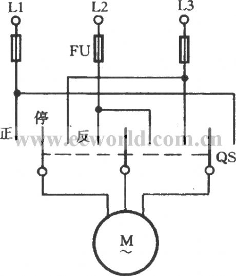
In order to change the turning of three-phase motor, it only needs to switch any two-phase wiring of three-phase power. In the occasion which is often needed to switch motor running direction, it can reach the goal by one double-throw plastic cover knife switch QS connected as shown. Methods of operation: normal knife switch handle is often in the center stop position; when it needs to forward, the knife switch handle could be pulled to the positive ; In order to change direction, that is, the swicth is pulled to the stop , then anti after the motor being stable.
(View)
View full Circuit Diagram | Comments | Reading(1253)
Three-phase motor and self-motivation - short braking circuit
Published:2011/7/9 6:13:00 Author:Lucas | Keyword: Three-phase motor, self-motivation - short, braking circuit
View full Circuit Diagram | Comments | Reading(764)
examination to broken rotor bar of three-phase motor
Published:2011/7/10 2:25:00 Author:Lucas | Keyword: rotor, three-phase motor
View full Circuit Diagram | Comments | Reading(852)
| Pages:1584/2234 At 2015811582158315841585158615871588158915901591159215931594159515961597159815991600Under 20 |
Circuit Categories
power supply circuit
Amplifier Circuit
Basic Circuit
LED and Light Circuit
Sensor Circuit
Signal Processing
Electrical Equipment Circuit
Control Circuit
Remote Control Circuit
A/D-D/A Converter Circuit
Audio Circuit
Measuring and Test Circuit
Communication Circuit
Computer-Related Circuit
555 Circuit
Automotive Circuit
Repairing Circuit