
Circuit Diagram
Index 1598
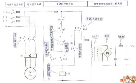
Tank-type water level control circuit
Published:2011/7/6 9:09:00 Author:John | Keyword: water level
View full Circuit Diagram | Comments | Reading(1313)
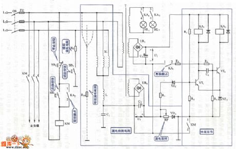
Voltage type leakage protection circuit
Published:2011/7/4 0:44:00 Author:John | Keyword: leakage protection
View full Circuit Diagram | Comments | Reading(879)
Scintillation Caution Light (5)
Published:2011/6/16 7:17:00 Author:Sue | Keyword: Scintillation, Caution, Light
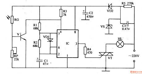
In the daytime, RG has a low resistance value because of the light, and V is connected. IC's pin 4 has a low level. The multivibrator doesn't work. IC's pin 3 still has low level. VT is not connected and HL is not illuminated.
At night, RG has a high resistance value because of lack of light, and V is disconnected. IC 'spin 4 has a high level. The multivibrator begins to work. IC's pin 3 outputs low pulse signals. VT is connected when the signal is positive and is disconnected when the signal is negative. Hl begins to twinkle. (View)
View full Circuit Diagram | Comments | Reading(564)
Four-tier telecommunications filter with ordinary frequency of 1KHZ circuit
Published:2011/7/4 0:44:00 Author:John | Keyword: Four-tier telecommunications filter
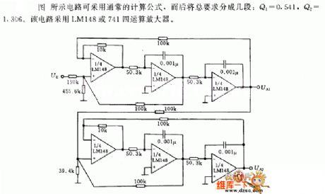
Four-tier telecommunications filter with ordinary frequency of 1KHZ circuit is shown in the following.
The circuit as shown can be applied for the usual formula, and the total requirements will be divided into several paragraphs: Q1 = 0.541, Q2 = 1.306. This circuit uses the LM148 or 741 four-operational amplifiers.
(View)
View full Circuit Diagram | Comments | Reading(723)
Pendant Light Controller (4)
Published:2011/7/5 21:56:00 Author:Sue | Keyword: Pendant Light, Controller
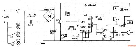
The first time the power switch S is connected, because C3's capacity is large, the moment S is connected, C3's voltage can't realise abrupt change, so IC's pin 14 outputs high level. V1 and V2 are disconnected. K1 is not connected. At this time, only the first group of illuminations EL1 are illuminated.
When S is connected quickly after disconnection, IC begins to work. Its pin 3 inputs a trigger high level pulse which will make trigger A1 reverse. Its pin 1 will output high level which will make V1 and K1 connected. K1's normally open contractor will be connected. Then the 2nd group of illuminations EL2 will be illuminated.
(View)
View full Circuit Diagram | Comments | Reading(669)
Pendant Light Controller (3)
Published:2011/7/5 22:06:00 Author:Sue | Keyword: Pendant, Light Controller
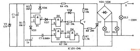
When S is connected, the 220v voltage will be put on the 3rd group of illuminations EL3 through S which will make EL3 illuminated. The other circuit will generate +12v voltage after it is rectificated by VD1-VD4, current-limited and voltage-reducted by M, filtrated by C1, stablized by VS. Apart from providing IC with working power, the +12v voltage will charge C2 through R2 and VD5.
When the +12v voltage is generated, because C2's voltage can't realise abrupt change, NOT gate D1's input terminals(IC's pin1 and pin2) have low level. Its output terminal(IC's pin 3)'s high level will charge C3 through VD7 which will make NOT gate D2's and D3's output terminal (IC's pin 4 and pin 10) have low level. V and VT are not connected. The first group of illuminations EL1 and the second group of illuminations EL2 are not illuminated. (View)
View full Circuit Diagram | Comments | Reading(753)
Active filter with variable state circuit
Published:2011/7/4 0:44:00 Author:John | Keyword: Active filter
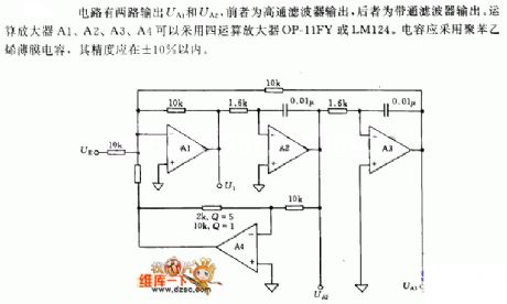
Circuit has two outputs which are named the UA1 and UA2. The former one is called high-pass filter output, and the later one is called band-pass filter output. Four-operational amplifiers four operational amplifiers OP-11FY or LM124 can be used for operational amplifiers A1, A2, A3 and A4. Polystyrene film capacitor can be used and its accuracy should be within ± 10%.
(View)
View full Circuit Diagram | Comments | Reading(783)
MAX809 reset circuit
Published:2011/7/4 0:35:00 Author:John | Keyword: reset
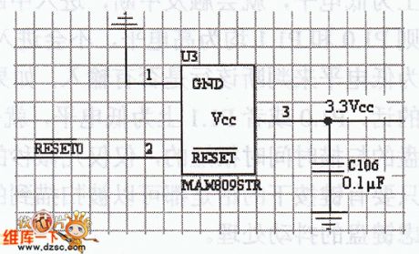
In the SCM system, MCU needs reset circuit, which can use R-C reset circuit or reset circuit achieved by reset chip. R-C reset circuit is economic. But it is not ratherreliable. The reset circuit achieved by reset chip is with high reliability. Therefore, in order to ensure the reliability of reset circuit, the system uses reset circuit achieved by reset chip. The system uses a MAX809 chip. And reset circuit is as shown below.
In order to reduce the interference of power supply, a 0.1μF capacitor is also needed to be placed on a reset chip's power input legs. Such can achieve the filtering and reduce disruption of the input end.
(View)
View full Circuit Diagram | Comments | Reading(841)
Pendant Light Controller (2)
Published:2011/7/5 23:17:00 Author:Sue | Keyword: Pendant Light, Controller
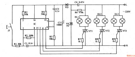
When S is pushed continuously, IC's pin 1 will input positive pulse signals continuously. Its output terminals(pin 6,pin 5,pin 4, pin 3) will output signals inbinary order of 0001-1000(0 is low level and 1 is high level). IC's pin3, pin 4 ,pin 5 are connected to VT3, Vm, VT1 respectively by R9, R8, R7. When one of IC's output terminals outputs high level, the controlled thyristor will be connected.That is when IC's pin 3 outputs high level, VT3 is connected and the 3rd circuit of illuminations EL3 are illuminated. When IC'spin 4 outputs high level, Vm is connected and the 2nd circuit of illuminations EU are illuminated. When IC's pin 5 outputs high level, VT1 is connected and the first circuit of illuminations EL1 are connected. (View)
View full Circuit Diagram | Comments | Reading(631)
MSP430F149 alarm circuit
Published:2011/7/4 0:35:00 Author:John
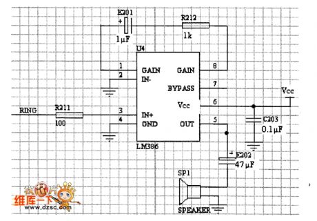
The main part of the circuit is to drive a buzzer. Once one end is grounded to the buzzer, the other end is connecting with the chip to take effects. Taking the drive capability of MSP430F149 into account, an amplifier is needed. The picture shows the implementation of the alarm circuit.
It can be seen through the figure that acquisition circuit is simple and practical.To reduce the effects from the power supply’s input ripple, a 0.1μF capacitor is added to the pin feet of the power supply for filtering.
(View)
View full Circuit Diagram | Comments | Reading(635)
Light-Operated Streetlight (14)
Published:2011/7/5 23:24:00 Author:Sue | Keyword: Light-Operated, Streetlight
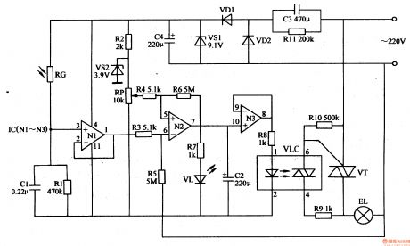
In the daytime, when there is strong light, RG has a low resistance value because of the light. N1 will output high level(about 8v) because its positive phase input terminal has a higher voltage than its negative phase input terminal. N2 and N3 both output low level. VLC's inside LED is not illuminated and the light-operated thyristors are not connected. VT is disconnected and EL is not illuminated.
In the evening, RG has a high resistance value because of lack of light, which will make N1 output low level(lower than 1v). N2 and N3 both output high level which will make VLC and VT begin to work. EL is illuminated.
When RP's resistance value is adjusted, EL can be illuminated when it is dark and can be off when daytime comes. (View)
View full Circuit Diagram | Comments | Reading(1514)
Serial communication circuit
Published:2011/7/4 0:30:00 Author:John | Keyword: Serial communication
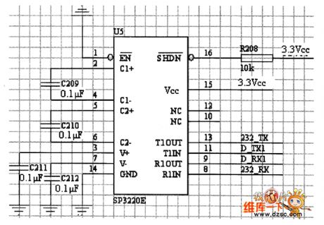
The system implements serial port module is mainly by communicating with the host computer. The microcontroller system will send the collected data to the host computer for processing, thereby reducing the processing burden on the system microcontroller. As electricity level is different when the microcontroller is communicated with the PC interface, interface conversion is needed. The SP3220 chip is used here to complete the conversion on interface’s electricity level. SP3220 chip is with low power consumption and small package and other features. Before the introduction of specific circuits, SP32 ⒛ chip is introduced. SP32 ⒛ chip has the following characteristics.
(View)
View full Circuit Diagram | Comments | Reading(818)
LM307 voltage-controlled gain amplifier circuit
Published:2011/7/4 0:28:00 Author:John | Keyword: gain amplifier
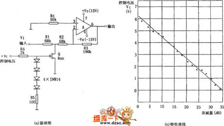
Voltage-controlled gain amplifier can be composed of approximate logarithmic relationship between the FET gate voltage and drain - source resistance RSD. The integrated circuit uses chip LM307 as an amplifier and uses inverting input form. According to figure (a), RSD and R1 form the voltage divider circuit (to divider pressure for Vi). The plus of 4 1N914 diodes’ voltage drop and the resistor R5’s voltage drop is equal to FET’s gate voltage VG. The VG is with the nonlinear relationship with the control voltage VC, but the correlation between the control voltage VC and the amplifier‘s gain attenuation is shown in figure (b) below. (View)
View full Circuit Diagram | Comments | Reading(1941)
TA8119 monolithic stereo playback integrated circuit
Published:2011/7/5 1:13:00 Author:chopper | Keyword: monolithic, stereo, playback, integrated circuit
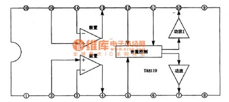
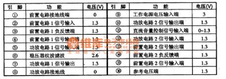
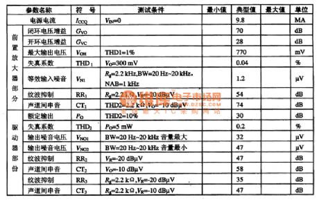
TA8119 is a monolithic playback integrated circuit produced by Japanese company TOSHIBA,and it is applied to mini cassette players.1.inner circuit and function of pins TA8119 integrated package includes playback circuit whose golden part is used in 3V stereo earplugs type cassette.The preamplifier and headphones are independent, and loop gain is 30db and it includes ripple wave as well as filtering wave and extensible dc voltage input level.The inner circuit of TA8119 integrated package is shown as picture 1.This IC has two encapsulation methods.
(View)
View full Circuit Diagram | Comments | Reading(2061)
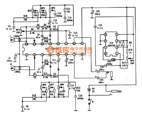
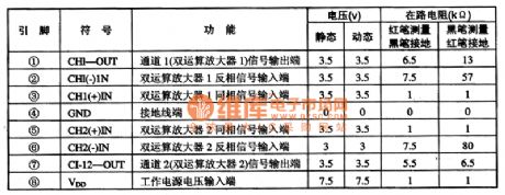
TA8111AP monolithic stereo playback integrated circuit
Published:2011/7/4 23:42:00 Author:chopper | Keyword: monolithic, stereo, playback integrated circuit
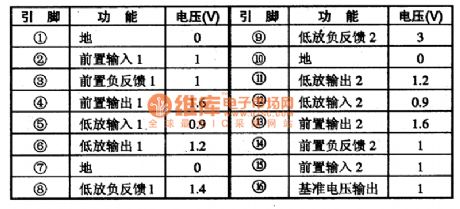
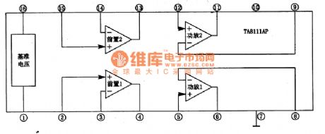
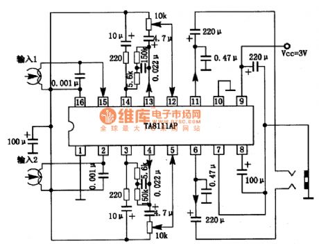
TA8111AP is a monolithic playback integrated circuit produced by Company TOSHIBA,and it is applied to mini acoustic system like low-voltage walkman and so on.1.inner circuit and function of pins The inner circuit of TA8111AP integrated package includes two same preposing equilibrium amplifier circuits,two same power amplifier circuits. This IC adopts dual inline 16 pinned package.Its function and data of pins are shown as chart 1.
(View)
View full Circuit Diagram | Comments | Reading(1498)
TA8106F double track headset drive integrated circuit
Published:2011/7/5 5:45:00 Author:chopper | Keyword: double track, headset drive, integrated circuit
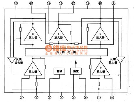
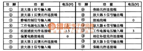
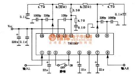
TA8106F is a dual track headset drive integrated circuit produced by Toshiba Company,and it is applied to mini,thin radio or cassette and recording radio as low-power drive circuit.1.The inner circuit and function of pins of TA8106FThe inner circuit of TA8106F integrated package includes two audio preamplifier premagnification circuits of same function,matrix power drive circuit,squelch circuit,biasing circuit,feedback amplifier circuit and so on.The inner circuit of the integrated package is shown as picture 1.This IC adopts dual inline 16 pinned flat package.
(View)
View full Circuit Diagram | Comments | Reading(1186)
TA75558P wide band with double operational amplifiers circuit
Published:2011/7/5 1:12:00 Author:chopper | Keyword: wide band, double operational amplifiers
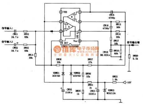
TA75558P is a wide band with double operational amplifiers circuit produced by company TOSHIBA.This IC is applied to the acoustic circuit as comparator or active low-pass filter.1.The inner circuit and function of pins of TA75558PThe inner circuit and typical application circuit of TA75558P integrated package are shown as picture 1.This IC adopts dual inline 8 pinned package.Its function and data of pins of the integrated circuit are shown as chart 1.
2.The typical application circuit of TA75558PTA75558P can be taken as active low-pass filter,The typical application circuit of its integrated package is shown as picture 1.
(View)
View full Circuit Diagram | Comments | Reading(2085)
MK5087+TWH630 Remote control transmit circuit
Published:2011/7/4 0:29:00 Author:John | Keyword: Remote control
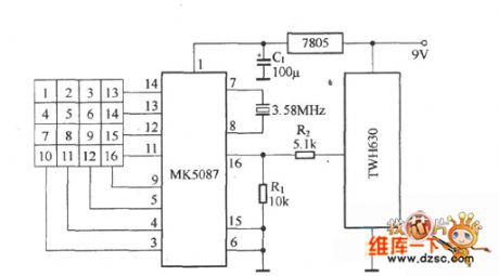
MK5087+TWH630 Remote control's transmit circuit is shown.
(View)
View full Circuit Diagram | Comments | Reading(1308)
landlines of power supply circuit
Published:2011/7/5 0:57:00 Author:chopper | Keyword: landlines, power supply circuit
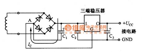
The power supply circuit is a high-power circuit,we should pay attention to the down-lead,or it will not gain low-noise supply.The picture is the positive supply circuit formed by full-wave rectification and three terminal regulator.In the circuit,the ground of smoothing capacity C1 and regulator is connected to point A. Point A is a reference potential.The landlines of regulator will effect a lot to the circuit performance.If there is noise or hun in the landlines,it will emerge on the output end.There is smoothing current Ic charged and discharged by capacitor through The landlines of smoothing capacity C1.The capacity C2 is a vibration control capacity.
(View)
View full Circuit Diagram | Comments | Reading(640)
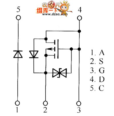
QS5U21 and QS5U23 internal circuit
Published:2011/7/6 9:09:00 Author:John | Keyword: internal circuit
View full Circuit Diagram | Comments | Reading(562)
| Pages:1598/2234 At 2015811582158315841585158615871588158915901591159215931594159515961597159815991600Under 20 |
Circuit Categories
power supply circuit
Amplifier Circuit
Basic Circuit
LED and Light Circuit
Sensor Circuit
Signal Processing
Electrical Equipment Circuit
Control Circuit
Remote Control Circuit
A/D-D/A Converter Circuit
Audio Circuit
Measuring and Test Circuit
Communication Circuit
Computer-Related Circuit
555 Circuit
Automotive Circuit
Repairing Circuit