
Circuit Diagram
Index 1586
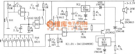
The intelligent control switch(with the time delay and anti-impact intelligent relay switch)
Published:2011/7/8 20:46:00 Author:Seven | Keyword: relay switch, intelligent control switch
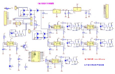
The intelligent control switch( with the time delay and anti-impact intelligent relay switch)
(View)
View full Circuit Diagram | Comments | Reading(750)
The multi-function alarm circuit composed of wireless receivers
Published:2011/7/10 10:08:00 Author:Seven | Keyword: multi-function alarm, wireless receivers
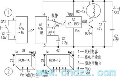
Working principles The circuit is shown in Figure 1, of which the wireless remote module A1 and battery G1, power supply SA1 compose the emitter; the wireless remote receiving module A2, analog sound integrated circuit A3 and so on compose the reception alarm.Usually, the aerial in A1 can emit the ultra-high magnetic wave of 250~300MHz into the around space, in the effective range, the wave is received by the micro reception aerial in module A2, and then it is modulated, amplified, detected, delayed and LEV converted by the internal circuit, finally, the pin outputs a low LEV.
(View)
View full Circuit Diagram | Comments | Reading(692)
The vibration inductance "monks chanting Buddhist scripts" circuit (LM386 and LH690)
Published:2011/7/10 10:17:00 Author:Seven | Keyword: vibration inductance, Buddhist scripts
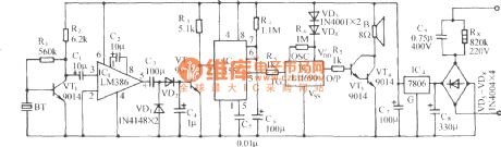
See as the figure, the circuit consists of the sensor, amplifier stage, rectifier circuit, single stable trigger circuit, monks chanting Buddhist scripts sound circuit and AC step-down rectifier circuit, etc. (View)
View full Circuit Diagram | Comments | Reading(738)
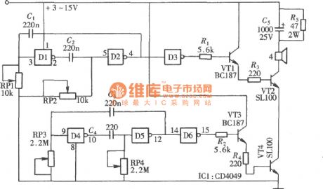
The finger touch high frequency photo/sound alarm circuit
Published:2011/7/8 20:29:00 Author:Seven | Keyword: high frequency, photo/sound alarm
See as the figure, the circuit consists of the touching power switch, SCR generating circuit, whistle sound making circuit and audio power amplifier circuit, etc. It can be used in banks and abodes as the emergency alarm. (View)
View full Circuit Diagram | Comments | Reading(673)
The alarm circuit composed of T630/T631
Published:2011/7/8 20:01:00 Author:Seven | Keyword: alarm circuit
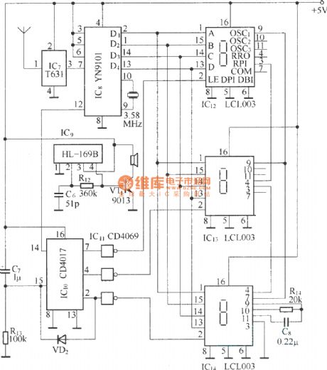
The probe of the circuit is a microwave sensing module RD9481, which is encoded by DTMF(dual-audio multi-frequency), the transmission of the alarm signal and address is done by the long wave transceiver unit T630/T631, the circuit can display the alarm spot, so it is suitable for multi-channel (16) integrated monitor alarm system. The circuit consists of the host and the extension, apart from the different address encode, all the extension circuits are the same.Alarm host circuit:
Alarm extension circuit:
(View)
View full Circuit Diagram | Comments | Reading(895)
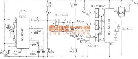
The remote alarm composed of SX-3
Published:2011/7/8 20:07:00 Author:Seven | Keyword: remote alarm
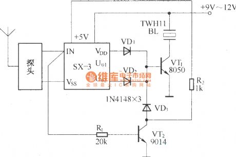
SX-3 human body inducting switch is a microwave control unit which works according to the Doppler effect, it is in a plate structure, the outline size is l00mm×50mm, its probe and signal processor can be divided into two parts, which is convenient to detect remotely, the circuit can be used in alarms, auto doors, auto lamps, auto audio control devices and so on. (View)
View full Circuit Diagram | Comments | Reading(660)
A durable alarm circuit
Published:2011/7/8 20:14:00 Author:Seven | Keyword: durable alarm
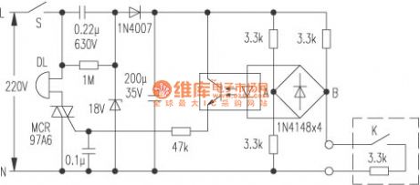
Many citizens have additional storerooms, as the storeroom is not at the same side with the living room, so it's not easy to realize when it is pried or the motor is stolen.Here is to introduce a storage door alarm, one wire of the alarm's is from the living room to the storeroom, as long as the owner close the door and turn on the alarm, whether it is pried or the external wire is cut off or short, the alarm will make the alarm sound.
(View)
View full Circuit Diagram | Comments | Reading(605)
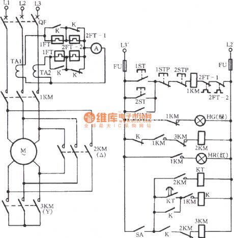
three-phase motor with △-starting and Y-running circuit
Published:2011/7/9 10:55:00 Author:Lucas | Keyword: three-phase motor
View full Circuit Diagram | Comments | Reading(825)
Automatic Transmission Circuit Eight of Southest Lingshuai Cars
Published:2011/7/7 21:28:00 Author:Michel | Keyword: Lingshuai Cars, Automatic Transmission, Circuit Eight
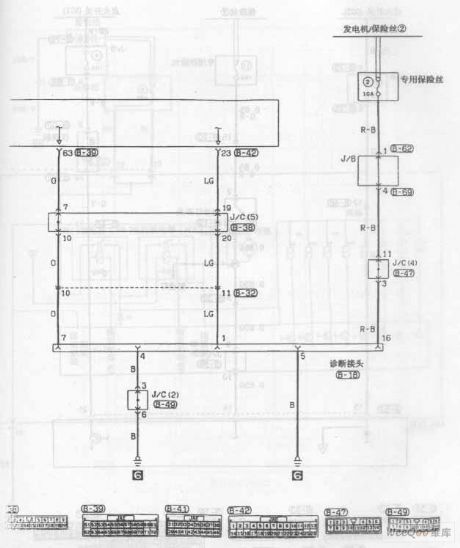
Automatic Transmission Circuit of Southest Lingshuai Cars (View)
View full Circuit Diagram | Comments | Reading(754)
VT66/66A Transistor Music Integrated Circuit
Published:2011/7/8 4:25:00 Author:Joyce | Keyword: VT66/66A, Transistor, Music, Integrated
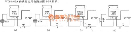
VT66/66 A is packed in TO92 form, and its appearance looks like 9013 transistor. What’s more, it has a piece of metal cooling fin and 3 leading feet.Since it is as convenient as general transistor, some give it the name music transistor. As shown in the figure is its typical application circuit.
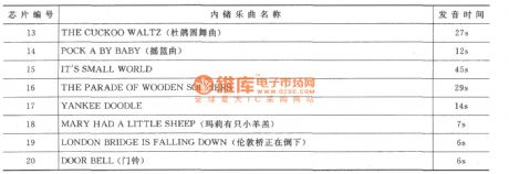
The relationship between the names of music stored in VT66/66 and chip numbers
src= /uploadfile/ic-circuit/20117842515914.gif border=0> (View)
View full Circuit Diagram | Comments | Reading(2331)
Light Control Music Integrated Circuit
Published:2011/7/8 4:39:00 Author:Joyce | Keyword: Light Control, Music , Integrated
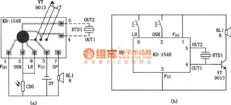
KD-1548 is a large-scale integrated circuit. It can realize the function of light control through connecting photo-resistor (CDS) externally; it can also work as an ordinary music integrated circuit. So it is widely used in electric reminders, alarm devices, electric toys, crafts, etc.The typical application circuit of KD 1548 as light control trigger is as shown in the figure(a) ; While figure(b) shows the situation when it is used as a common music integrated circuit. At this moment, if pressing the button OSH only, the circuit will be triggered and it will automatically stop when a song is finished. If pressing LH, the music will start, but it will stop once you loosen LH. (View)
View full Circuit Diagram | Comments | Reading(1091)
Password Electronic Doorbell Circuit
Published:2011/7/8 1:43:00 Author:Joyce | Keyword: Password, Electronic , Doorbell
The password electronic doorbell is actually one that can tell whether it is a member of family and a visitor .Because a family member knows the password, when he presses the password, the doorbell will give out a kind of music. While a visitor does not know the password, so he presses a pseudo code and the doorbell will give out a specific sound, which enable the host to distinguish family members and visitors .The circuit is as shown in the figure. The circuit is composed by a four-two input Schmitt trigger CD4093 and two sound circuits, of which three doors of CD4093 D1 ~ D3 and buttons SA1 ~ SA3 forming a logic control circuit. (View)
View full Circuit Diagram | Comments | Reading(996)
Ring-simulated Doorbell Circuit
Published:2011/7/8 1:58:00 Author:Joyce | Keyword: Ring-simulated, Doorbell
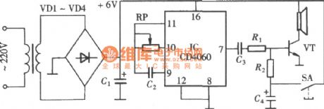
As shown in the figure, the circuit uses a 14 bit binary serial count/frequency divider and an oscillator of CD4060 oscillator to produce oscillating impulse with certain frequency. The oscillating impulse will send out a doorbell simulating that of a ring after certain processing. The main circuit is composed by a 14 bit binary serial count/frequency divider and oscillator CD4060. (View)
View full Circuit Diagram | Comments | Reading(1221)
Multifunctional Music Doorbell Circuit
Published:2011/7/8 1:30:00 Author:Joyce | Keyword: Multifunctional, Music Doorbell
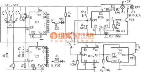
Multifunctional music doorbell has three functions.First, it can set a password; second, it has the function of avoiding disturbance; thirdly, it can inform whether the host is in. The circuit is as shown in the figure. It constitutes of a password setting circuit, control switch and doorbell music circuit. IC1,IC2 is CD4017; IC3a is one flip-flop of the double D flip-flop CD4013. It composes a monostable trigger with R8, C4 . (View)
View full Circuit Diagram | Comments | Reading(980)
Touch Flash Buzzer Circuit
Published:2011/7/8 2:48:00 Author:Joyce | Keyword: Touch , Flash , Buzzer
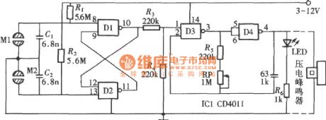
As shown in the circuit is a touch flash buzzer circuit composed of a four-two input end NAND gate CD4011. (View)
View full Circuit Diagram | Comments | Reading(1069)
Multitone Buzzer Circuit
Published:2011/7/8 3:38:00 Author:Joyce | Keyword: Multitone, Buzzer
As shown in the figure, the multitone buzzer is composed of a six inverse buffer converter CD4049.It can produce a lot of tones if it is adjusted. In this circuit, four gates of CD4049 form two groups of multivibrator respectively. The buzzer will produce sound after being driven by output of the logic control gate after buffering and transforming. (View)
View full Circuit Diagram | Comments | Reading(1406)
Electronic Music Box Circuit
Published:2011/7/8 3:55:00 Author:Joyce | Keyword: Electronic , Music Box
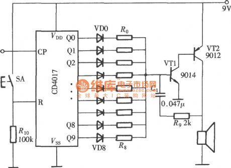
As shown in the figure is an electronic music box circuit composed of CD4017 (View)
View full Circuit Diagram | Comments | Reading(4116)
Light-Operated Streetlight (12)
Published:2011/7/1 6:14:00 Author:Sue | Keyword: Light-Operated, Streetlight
The 220v voltage will generate +12v voltage after reduction and stablization. The voltage will be put on IC. The other circuit will provide IC's pin 5 with voltage.
In the daytime, RG will have a low resistance value which will make IC's pin 5 have a low level. IC's inner switch will be disconnected. Its pin 2 and pin 3 will output low level and VT is disconnected. EL is not illuminated.
When it is dark, RG will have a high resistance value which will make IC's pin 5 have a high level. IC's inner switch will be connected. Its pin 2 and pin 3 will output high level. VT is connected and EL is illuminated. (View)
View full Circuit Diagram | Comments | Reading(562)
Light-Operated Streetlight (11)
Published:2011/7/1 6:09:00 Author:Sue | Keyword: Light-Operated, Streetlight
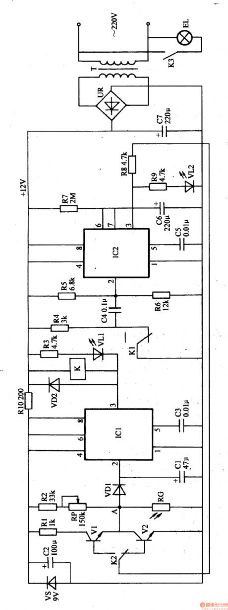
The 220v voltage will provide IC2 with working voltage after the reduction, rectification and filtration. The other circuit will provide the light-operated circuit with Vc voltage.
In the daytime, RG has a low resistance value because of the light. IC1's pin 2's working voltage is higher than 2Vcc/3. IC1's pin 3 will output low level which will make K connected. EL is not illuminated. At the same time, IC2's pin 3 will output high level which will make V2 connected. IC1's pin 2 will output low level. V2 is disconnected.
When it is dark, RG has a higher resistance value. IC1's pin 2's voltage will be lower. When pin 2's voltage is lower than Vcc/3, IC1's pin 3 will have a high level. K is released. V1 is connected. (View)
View full Circuit Diagram | Comments | Reading(562)
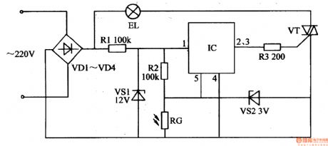
Light-Operated Streetlight (9)
Published:2011/7/1 5:57:00 Author:Sue | Keyword: Light-Operated, Streetlight
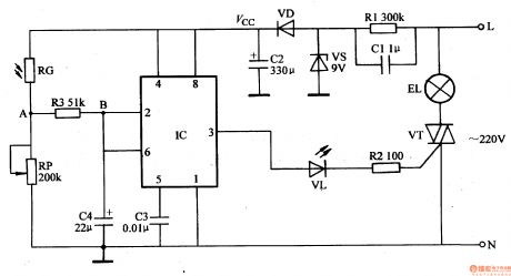
The 220v voltage will provide IC with 8.5v working voltage after reduction, stablization, rectification and filtration.
In the daytime, RG has a low resistance value because of the light. IC's pin2's and pin 6's voltages are larger than 2Vcc/3, and IC's pin 3 outputs low level. VL is not illuminated. VT is disconnected and EL is not illuminated.
When it is dark, RG has a larger resistance value and IC's pin2's and pin 6's voltages are becoming smaller. When the voltage is higher than 2Vcc/3, IC's inner trigger will be reversed. Its pin 3 will have a high level which will make VL illuminated. VT is illuminated and EL is illuminated.
When the next day comes, RG has a smaller resistance value. IC's pin 2's and pin 6's voltage are becoming larger. When the voltage is lower than Vcc/3, IC's pin 3 has a low level. VL and VT are disconnected. EL is not illuminated. (View)
View full Circuit Diagram | Comments | Reading(617)
| Pages:1586/2234 At 2015811582158315841585158615871588158915901591159215931594159515961597159815991600Under 20 |
Circuit Categories
power supply circuit
Amplifier Circuit
Basic Circuit
LED and Light Circuit
Sensor Circuit
Signal Processing
Electrical Equipment Circuit
Control Circuit
Remote Control Circuit
A/D-D/A Converter Circuit
Audio Circuit
Measuring and Test Circuit
Communication Circuit
Computer-Related Circuit
555 Circuit
Automotive Circuit
Repairing Circuit