
Circuit Diagram
Index 1591
The relay pulling-in precaution circuit in low voltages
Published:2011/7/8 0:17:00 Author:Seven | Keyword: relay, pulling-in precaution, low voltages
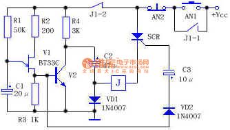
Working principle: see as the figure, V1 is a single knot transistor BT33C, which consists of the relaxation oscillator with R1, R2, R3 and C1, SCR is the single-way SCR, after AN1 is pressed, the circuit is passable, the SCR is not conducting without trigger voltage, the relay J is not working, the power supply charges C2 quickly and makes its voltage close to it(Vcc-VD1 voltage drops). At the same time, the power supply is charging C1 with the help of C1. In seconds, the voltage of C1 reaches the trigger voltage of V1, so C1 is discharging through V1. (View)
View full Circuit Diagram | Comments | Reading(771)
The principle profile of the 62.4V/10A charger
Published:2011/7/8 0:07:00 Author:Seven | Keyword: principle profile, charger
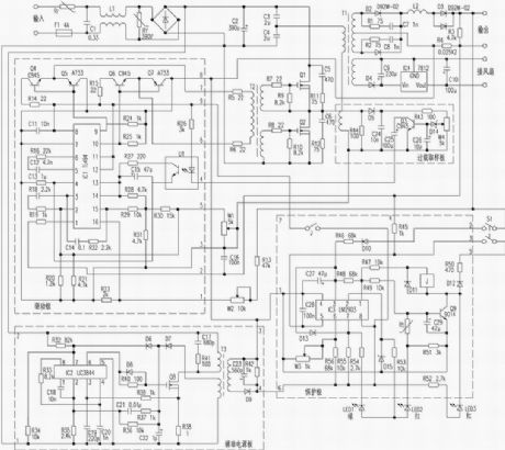
High-frequency switch motor is popular in the market due to its little size and high efficiency. Not long ago, the writer got a 62.4v/10A high-frequency switch charge core with the cooling fan from Xiangqiao Corp., the writer think it's worthwhile. To make it easy to repair, the writer has drawn the principle circuit, the introduction is as follows: The core consists of 4 modules which are main board drive, additional power supply, protection and overload sampling, and the main board includes the mains rectifier, power converter, high frequency rectifier and so on.
(View)
View full Circuit Diagram | Comments | Reading(889)
The lighting lamp auto switch circuit of dual-way thyristor
Published:2011/7/8 1:54:00 Author:Seven | Keyword: lighting lamp, auto switch, dual-way thyristor
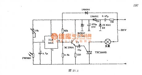
The switch controls the 200W lamps, the power supply is 220V, when the light is 100lx or so, the left and right lamps will turn on/off automatically. The LDR is in a high resistance when it's dark outside, the voltage on the input terminal of the threshold switch is 0.7 time higher than 2-pin, and its output terminal is in a high resistance, so the forward half circle of the gird voltage is passable after it is distributed by the transistor, and in each half-circle, there generates a trigger pulse, which makes the load get power. When the light is strong (higher than 100lx), the output terminal of the threshold switch is negative.
(View)
View full Circuit Diagram | Comments | Reading(3050)
The passive human body infrared sensor circuit
Published:2011/7/8 0:58:00 Author:Seven | Keyword: human body, infrared sensor
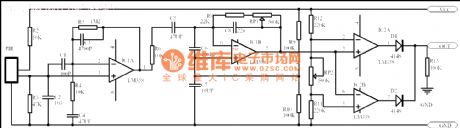
No matter what kind it is, passive human body infrared sensor circuits are almost the same with the above, maybe some has less stages. This circuit in the figure is got from the NICERA producer, which is classical. The stage of front-end is the low frequency signal amplifier, the magnified times are 100, then the signals pass R6 and C5 before the 0.2-10HZ signal is picked out, finally, the selected signal is amplified by IC1B, the 5-pin of the op-amp is the 1/2VCC voltage pin, when it is static, the voltage on 6-pin and 7-pin is also 1/2VCC.
(View)
View full Circuit Diagram | Comments | Reading(2079)
The self-lock switch circuit
Published:2011/7/8 1:23:00 Author:Seven | Keyword: self-lock switch
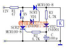
The action machines or contactors of ordinary converter switches or toggle switches are easy to break, at the same time, they are easy to burn due to the large impact of currents. Here is to introduce a simple circuit which can replace this switch. See as the above circuit, before AN is pressed, SCR1 is blocked, the relay or contactor is still, which is equal to the cut off state. When AN is pressed, the 12V voltage provide with trigger current for SCR1 through R1, AN and VD1, and SCR1 is conducting, K is getting power, the load is connected by the contactor and getting into work. (View)
View full Circuit Diagram | Comments | Reading(1314)
The general alarm circuit with time delay function
Published:2011/7/8 1:09:00 Author:Seven | Keyword: alarm circuit, time delay function
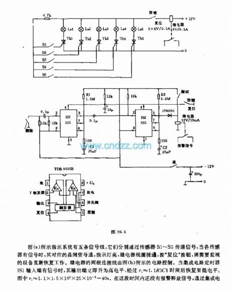
The system in figure (a) has five signal lines which deliver signals with sensors of S1~S5 respectively, when the sensors get signals, the relative thyristors are conducting, the indicators are glowing, the relay coil is getting through, by pressing the key of reset , the monitoring devices are working again. Two of the relay lines are controlled by the circuit in Figure (b). When the timer IS1of the integrated circuit, the output terminal is in a low LEV quickly, but it will return to the low LEV in the time of t1≈1.1R1C1. (View)
View full Circuit Diagram | Comments | Reading(727)
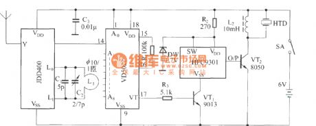
The bike burglarproof alarm circuit
Published:2011/7/8 2:20:00 Author:Seven | Keyword: bike, burglarproof alarm
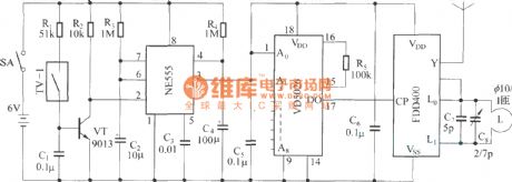
The remote emitting circuit:
The remote receiving circuit:
(View)
View full Circuit Diagram | Comments | Reading(705)
The long-distance alarm raster circuit
Published:2011/7/8 1:43:00 Author:Seven | Keyword: long-distance, alarm raster
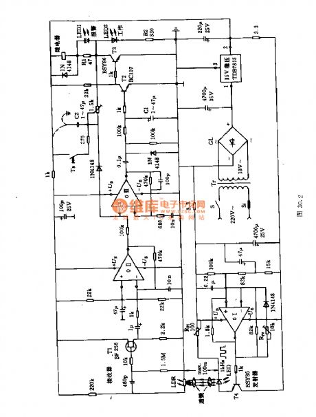
The circuit consists of two parts, the emitter and receiver. The former consists of the computing amplifier 01, the capacitor C3 can be rectified to 1kHz, the potentiometer Rpz regulates the width of the pulse ultra-sonic wave, the potentiometer Rp1 limits the emitting current in a certain range. The input terminal of the receiver is the LDR or the optical transistor. The pulse light is converted into the AC current, the computing amplifier 0II is controlled by the FET T1, and its output controls the amplifier 0III. To allow it to receive signals in bad or remote environments, the signal from the 0III needs to by magnified by T2 and T3.
(View)
View full Circuit Diagram | Comments | Reading(807)
The intelligent "Wisdom in an Empty City" anti-burglar photo/sound control circuit
Published:2011/7/8 2:17:00 Author:Seven | Keyword: Wisdom in an Empty City, anti-burglar, photo/sound control circuit
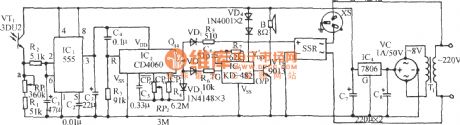
In the storerooms without human duty or homes often without people, the experienced thieves often do this thing at after midnight. The control circuit can make sound and light after in 4-6h of darkness, the thieves don't know the real condition, so they won't take action. At daytime, the circuit is static, which is safe and energy-saving. See as the figure, it consists of the light control switch circuit, preset timer circuit, AC relay control circuit, music making circuit and power supply circuit, etc. (View)
View full Circuit Diagram | Comments | Reading(620)
The antique anti-moving alarm circuit
Published:2011/7/8 2:01:00 Author:Seven | Keyword: antique, anti-moving alarm
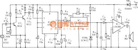
See as the figure, the circuit consists of the mercury switch, single stable trigger, power switch, sound generating circuit and audio power amplifier circuit, etc. The alarm is put in the antique case or in the antique, when some is stealing or moving it, the circuit will make sound of catch the thief repeatedly. (View)
View full Circuit Diagram | Comments | Reading(668)
The antique anti-burglar audio alarm ring of vibration
Published:2011/7/8 2:06:00 Author:Seven | Keyword: antique, anti-burglar, audio alarm
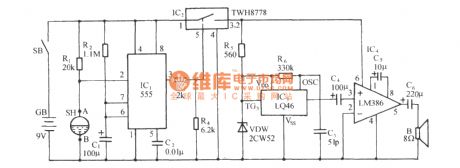
See as the figure, the circuit consists of the piezoelectric pottery sensor, sound/electric converter and amplifier, single stable timing circuit, language sound making circuit, audio power amplifier circuit and so on. (View)
View full Circuit Diagram | Comments | Reading(741)
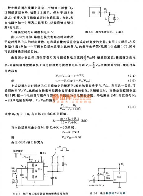
The inductance burglarproof alarm circuit
Published:2011/7/6 22:18:00 Author:qqtang | Keyword: inductance, burglarproof alarm
Whether the thief is wearing a glove or not, as long as the hand is within 5~80mm away from the alarm inductor, the alarm will make sound. See as the figure. The inductor is represented with G, and there is a distributing capacitor between G and the ground, Co, L, C1 and V1 compose the 3-pole oscillator, in the circuit composed of Co, C1 and L, judging from the AC circuit, Co is serially connected with C1. When there is no one getting close to G, Co is low, when it is serially connected with C1, the voltage on the two terminals is high. (View)
View full Circuit Diagram | Comments | Reading(560)
Work Principle of 555 Monostable Model
Published:2011/7/5 0:01:00 Author:Zoey | Keyword: Work Principle, 555 Monostable Model
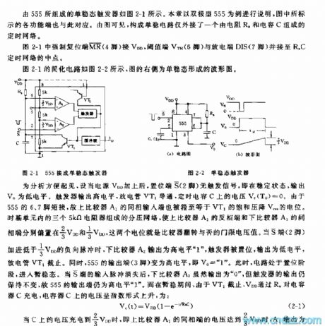
The Monostable multi-vibrator composed of 555 has been shown in the picture 2-1.This chapter takes the bipolar 555 as an example; functional terminals marked in the picture are relevant to each other. This monostable circuit has jointed a time network that consists of a resistance Ra and a capacitor C.
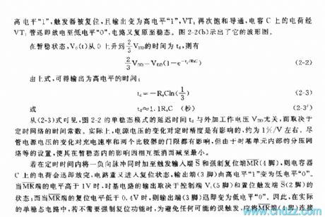
In the picture 2-1, the coercive resetion terminal pin 4 connects VDD, threshold terminal pin 6 VTH and discharge terminal DIS pin7 connect to the midpoint of RaC time network. Picture 2-2 is the simplified circuit, the right one is the waveform of monostable circuit.
When in a stable state, the output voltage V0 is in low level; when the circuit in a temporary stable state, voltage on the capacitor ascends exponentially:
Vc(t)=VDD(1-e-1/RaC)
When voltage on the capacitor reaches to 2/3VDD, the circuit backs to be stable. When the circuit is in a temporary stable state, the time that V0(t) takes to ascend from 0 to 2/3VDD is td:
2/3VDD-VDD(1-e-td/RaC)
From the formulas above, we can conclude that time of outputting high level:
td=-RaCln(1/3)
td≈1.1RaC(s)
The prolonged time of monostable model td is irrelevant to outer voltage VDD but is determined by time constant of time network. (View)
View full Circuit Diagram | Comments | Reading(1045)
Choice of Circuit Parameter outside 555 Monostable Work Mode
Published:2011/7/5 0:03:00 Author:Zoey | Keyword: Choice, Circuit Parameter, 555 Monostable Work Mode
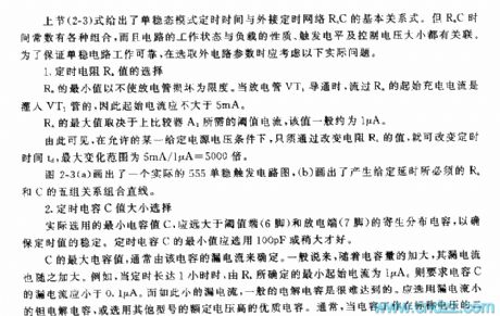
Basic relationshipbetween monostable model timingand timing network RaC has been shown in picture 2-3.As RaC’s time constant has various mixes, and operation of the circuit is relevant to property of load, trigger level and voltage controlled. Following factors should be taken into consideration to guarantee normal operation of the monostable circuit.
1 Choose a proper value of the time resistance Ra
The minimum value of RaC can be set only if the discharge tube won’t be broken and the maximum value of RaC is determined by threshold current on the comparator A1.
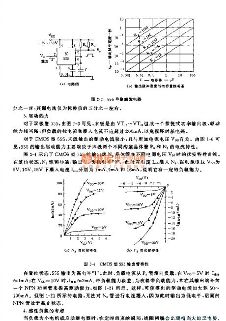
2 Choose a proper value of time capacitance
The minimum value of shall be 100pf or a little bit larger and the maximum value is determined by the leakage current of the capacitor.
3 Driving power
Driving power of 555 is mainly determined by the current property of transistor P6 and Na.
4 Take sensitive loads into consideration
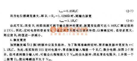
5 Set an accurate time and controllable voltage V
If value of RaC has been set, output pulse width is determined by Vc/VDD. Changing the ratio Vc/VDD to make up the changes arose by capacitance of capacitor, we can set an accurate time.
(View)
View full Circuit Diagram | Comments | Reading(972)
555 Monostable Circuit with a Changeable Width
Published:2011/7/5 0:05:00 Author:Zoey | Keyword: 555 Monostable Circuit with a Changeable Width
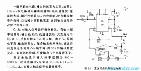
For a general monostable circuit, the pulse width output is a fixed value. As shown in the picture 2-9, pulse in the circuit uses a closed loop to control the manipulative terminal after being magnified, when trigger frequency rises, the temporarily stable pulse width will be narrowed, thus the duty cycle of the wave output remains unchanged.
C2 and R2 trigger the signal input differentially. As the trigger frequency increases, the direct level increases, Vc terminal decreases, and output width of 555 is narrowed. Loop-controlling makes duty cycle output remain unchanged.
Suitable frequency scope for the parameter is 500~5000Hz.When design the circuit, this condition should be guaranteed:R1C1≤1.1Tmin=1.1/fmax,fmax refers to the maximum frequency of trigger signal input. (View)
View full Circuit Diagram | Comments | Reading(1114)
555 Linear Voltage/Frequency Converter Circuit (Three)
Published:2011/7/5 0:07:00 Author:Zoey | Keyword: 555 Linear Voltage, Frequency Converter, Circuit
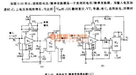
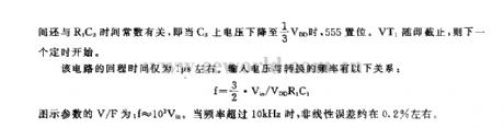
As shown in the picture 5-36, this linear voltage/frequency converter is a practical voltage/frequency converter. When input voltage is strengthened, voltage on C1 will have a linear increase, when it reaches 2/3 VDD, VT1 will conduct and make VT1 discharge promptly. Backhaul time is related to R5C3 time constant. That is,as soon asvoltage on C3 declines to 1/3 VDD, 555 will reset.VT1 will ceases to work, then next timing begins.
Backhaul time of this circuit is only 1μs. The relationship between voltage input and converter frequency can be expressed by following formula:
f=3/2•Vin/VDDR1C1
V/F of parameter in the picture is f ≈10³Vin. If frequency exceeds 10kHz, nonlinear error will be about 0.2%.
(View)
View full Circuit Diagram | Comments | Reading(945)
control the water level circuit consisting of 555
Published:2011/7/7 7:15:00 Author:Fiona | Keyword: control the water level
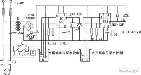
The control circuit consists of step-down rectifier circuit, 555 trigger circuit (IC1, IC2), relay control circuit and so on. When the water level probe of the tower B, D is above the water level line, IC1 ② feet is ground potential to make the IC1 place set,the high level output by ③ pin makes the relay J1pick up, contactor J1 -1 is closed,the pumping motor has electricity and runs to pump water; when the water level rises to probe A, corresponding IC1 is reset, the outpu low level makes J1 release,contactor J1-1 breakes,the pumping motor loses the power and stops running, so that it realizes the automatic control of water tower water level.
(View)
View full Circuit Diagram | Comments | Reading(847)
555 Linear Voltage/Frequency Converter circuit (Two)
Published:2011/7/4 23:03:00 Author:Zoey | Keyword: Linear Voltage, Frequency Converter, circuit
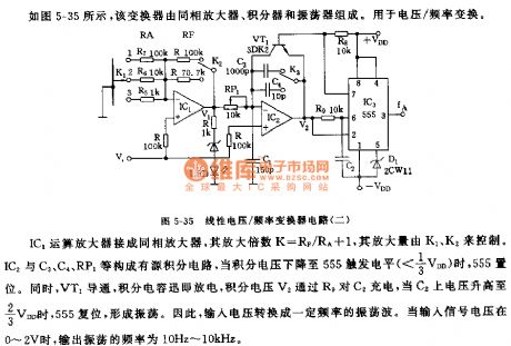
As shown in the picture 5-35, this converter is composed of a non-inverting amplifier, an integrator and an oscillator for voltage/frequency conversion.
When jointed to the amplifier, amplification factor K=RF/RA+1 and it is controlled by K1 and K2. IC2, C1, C4 and RP1 constitute a circuit with an active integral, when integral voltage declines to 555 trigger level(<1/3VDD), 555 will set. Meanwhile, VT1 will conduct; integral capacitance will discharge promptly, integral voltage V2 will charge to C2 via R9. When voltage on C2 ascends to 2/3VDD, 555 will reset and give rise to oscillation. Therefore, voltage input is converted to oscillation wave with some frequencies. When input signal ranges from 0 to 2V, frequency of input oscillation varies within the limit from 10Hz to 10 kHz. (View)
View full Circuit Diagram | Comments | Reading(778)
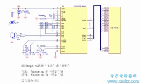
feike and Shinco air-condition remote controller circuit(bridle wire selection)
Published:2011/6/19 3:45:00 Author:Lena | Keyword: air-condition, remote controller, bridle wire selection
View full Circuit Diagram | Comments | Reading(604)
Illumination Controller (9)
Published:2011/7/6 0:37:00 Author:Sue | Keyword: Illumination, Controller
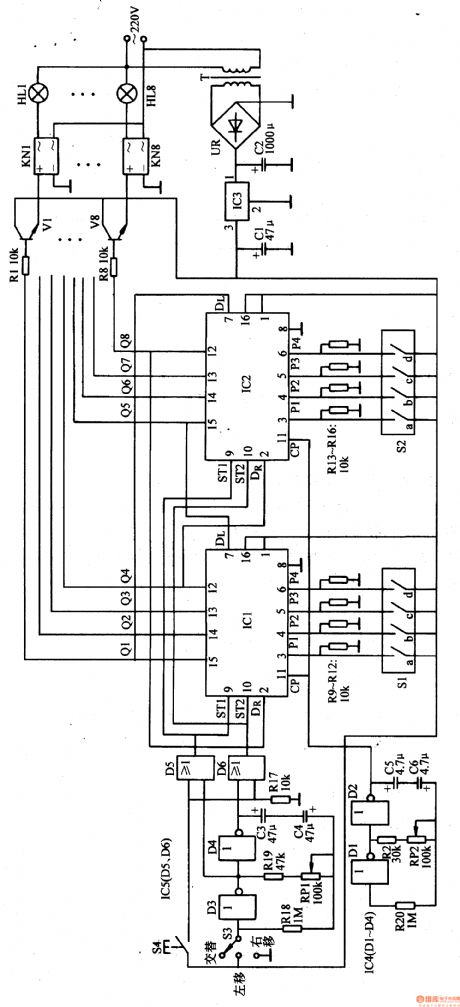
When the terminal outputs high level, the corresponding KN makes the illumination circuit connected. When the terminal outputs low level, KN makes the illumination circuit disconnected. For example, when Q1 terminal outputs high level, V1 is connected which will make KN1 connected. The first circuit of illuminations will be illuminated. When Q1 terminal becomes low level. V1 is disconnected and KN1 is disconnected. HL1 are off.Q1-Q8 keep changing the states under the control of the clock pulse. Then HL1-HL8 will be controlled to show various illumination effects.
S1 and S2 are used to set the initial state of the bidirectional shift register. Then push S4, write the set parameter to the shift register. If S1 is connected and P1 terminal outputs high level, IC's Q1 terminal will output high level.
S3 changes the shift register's shift directions by controlling the low-frequency multivibrator. Put 53 to ALTERNATION , the low-frequency multivibrator will begin to work. (View)
View full Circuit Diagram | Comments | Reading(650)
| Pages:1591/2234 At 2015811582158315841585158615871588158915901591159215931594159515961597159815991600Under 20 |
Circuit Categories
power supply circuit
Amplifier Circuit
Basic Circuit
LED and Light Circuit
Sensor Circuit
Signal Processing
Electrical Equipment Circuit
Control Circuit
Remote Control Circuit
A/D-D/A Converter Circuit
Audio Circuit
Measuring and Test Circuit
Communication Circuit
Computer-Related Circuit
555 Circuit
Automotive Circuit
Repairing Circuit