
Circuit Diagram
Index 1599
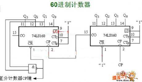
60-nary counter circuit
Published:2011/7/6 9:09:00 Author:John | Keyword: counter
View full Circuit Diagram | Comments | Reading(565)
Capacitor feedback oscillator circuit
Published:2011/6/12 20:43:00 Author:John | Keyword: feedback oscillator
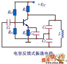
In order to obtain better output voltage waveform, it is better to exchange the locations of capacitor and inductor and to set public end of two capacitors to the ground. And collector resistance Rc is added. Therefore, the capacitor feedback oscillator can be achieved, just as shown in right figure. Because three terminals of two capacitors are connected respectively to three poles of the transistor, this circuit is also known as capacitor three-point circuit.
(View)
View full Circuit Diagram | Comments | Reading(553)
CD4060 oscillator frequency circuit
Published:2011/6/12 20:44:00 Author:John | Keyword: oscillator
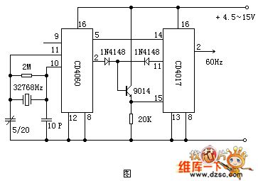
The quartz oscillator frequency can be corrected and frequency on pin 9 can be measured by a frequency counter CD4060 about 32768Hz. If the deviation exists, adjust the variable capacitor slightly to be corrected. The figure shows a time base signal generator composed of a CD4060 of 60Hz. Compared to former circuits, this is the most useful one of several time-base signal circuits.
(View)
View full Circuit Diagram | Comments | Reading(9907)
MIC5158 battery charger circuit
Published:2011/6/23 10:10:00 Author:chopper | Keyword: battery charger circuit
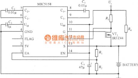
The constant-current charge circuit of MIC5158 is shown as the following picture.This circuit offers a constant current during the charging process(35mV/R3) until the voltage Uf1 is equal to 1.235(1+R1/R2).As for the formula,Uf1 is floating charge voltage(V).MOSFET tube will be cut off when the circuit reaches the floating charge voltage.Charge current is offered by R4. (View)
View full Circuit Diagram | Comments | Reading(1071)
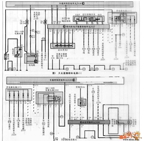
Volkswagen Jetta sedan car circuit
Published:2011/7/6 9:08:00 Author:John | Keyword: car
View full Circuit Diagram | Comments | Reading(888)
FAW-Volkswagen Jetta 2005 model car maintenance information circuit
Published:2011/7/6 9:07:00 Author:John | Keyword: car, maintenance information, car
View full Circuit Diagram | Comments | Reading(895)
STV9379 field scanning output integrated circuit
Published:2011/6/28 3:13:00 Author:chopper | Keyword: field scanning, output, integrated circuit
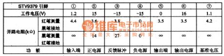
STV9379 is a special field scanning output integrated circuit and it is applied to Sony large-screen color TV widely as well as cassette mechanism large-screen color TV made in China of Sony cassette mechanism.1.function characteristicsSTV9306 integrated circuit includes field scanning output driving circuit,field scanning output circuit,voltage reference providing circuit,and other miscellaneous function circuit.2.function and data of pinsSTV9306 integrated circuit uses positive and negative power supply and adopts 7 pins single inline package and the function and data of pins of the integrated circuit are shown as chart 1.
(View)
View full Circuit Diagram | Comments | Reading(781)
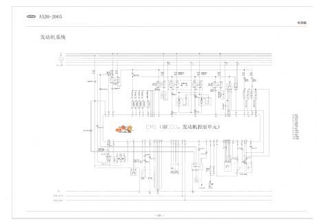
Chery A5/A520 full car circuit
Published:2011/7/6 9:07:00 Author:John | Keyword: full car
View full Circuit Diagram | Comments | Reading(2231)
diode protection circuit
Published:2011/7/6 7:38:00 Author:chopper | Keyword: diode, protection circuit
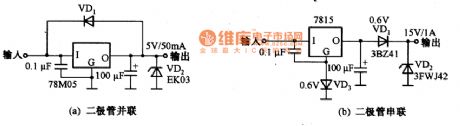
The protection circuit which utilizes commutation of diode and the characteristic of low forward-direction voltage drop is shown as picture a,b.Just as picture(a),VD1 will be conductive when output voltage is higher than input voltage;and when output voltage is less than input voltage,VD2 will be conductive in order to protect the power supply.VD2 adopts the Schottky diode whose forward-direction voltage drop is low.Picture(b) is a diode protection circuit in series.When output voltage is higher than power supply,VD1 will stop to protect the power suply.When the circuit is in normal operation,there is 0.6V forward voltage drop on VD1,and it will decrease the output voltage.Therefor,we can use output voltage of VD3 to compensate.
(View)
View full Circuit Diagram | Comments | Reading(1084)
MC1563 audio power amplifier circuit
Published:2011/7/5 1:14:00 Author:chopper | Keyword: audio, power amplifier
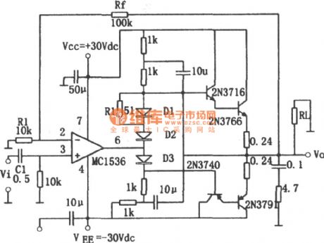
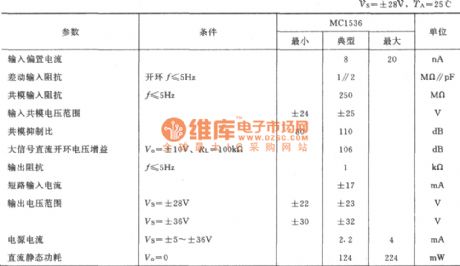
Figure shows the audio power amplifier. The circuit uses a high-voltage, internally-compensated integrated operational amplifier MC1536 .When the supply voltage Vs = ± 36V, the swing amplitude of output voltage is up to ± 30V, the maximum available supply voltage is up to ± 40V, input bias current is small (about 20nA below).The input offset current is less than 3nA, open-loop differential-mode gain is up to 5 × 10⁶ (typical value). The chip is suitable for low-frequency amplification.
(View)
View full Circuit Diagram | Comments | Reading(1003)
IX0640CE IC Typical Application Circuit
Published:2011/7/5 2:31:00 Author:Robert | Keyword: IC, Typical, Application
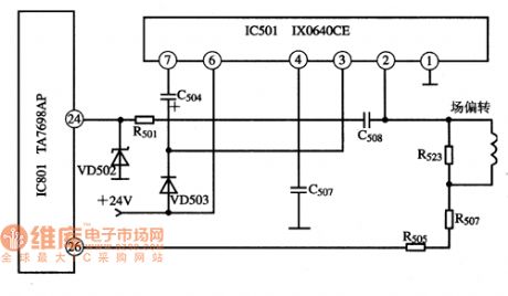
The 1X0640CE is a field scanning IC produced by the Japanese SHARP company. It is widely used in many kinds of domestic and imported color TV sets.
The IX0640CE IC's typical application circuit is shown in the picture.
The picture shows the IX0640CE IC's typical application circuit.
The IX0640CE IC itself has a small heatsink. The market has two types of IX0640CE which are the same models according to the connection method between the heatsink and its pin ①.
One type is that the resistance is ∞ between its pin ① and the heatsink. That means this type heatsink of the IX0640CE could be connected to the ground directly.
The other type is that there are positive and negative direction resistances (which can be measured in the Rx stage) between its pin ① and the heatsink. That means the heatsink is isolated from the ground. (View)
View full Circuit Diagram | Comments | Reading(975)
Circuit Diagram of Gaining 0~284V Voltage by concatenation of 2 voltage regualtor
Published:2011/6/25 10:47:00 Author:Vicky | Keyword: 0~284V Voltage, concatenation of 2 voltage regualtor
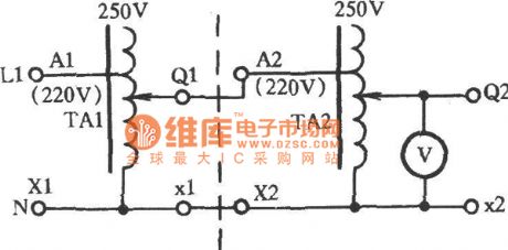
As shown in the picture, by concatenation of 2 voltage regulator, 0~284V voltage then is gained. Connect X1 and X2 of TA1 and TA2 respectively together by a conductor trace line, and then connect them to null line N of power supply; connect Al and X1 to power supply of 220V. Connect TA1 output end Q1 to end A2 of TA2. After energized, 0~ 284 voltage also can be gained in the TA2 output end Q2 and the voltage regulating is smooth. (View)
View full Circuit Diagram | Comments | Reading(608)
The precious domestic appliance burglarproof alarm
Published:2011/7/6 20:45:00 Author:qqtang | Keyword: domestic appliance, burglarproof alarm
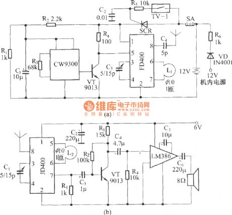
This precious domestic appliance burglarproof alarm is different from other alarms, it is installed in the householde appliance shell. In the shell, on the one hand, there is the battery as the working power supply, on other other hand, the low voltage power supply in the shell is taken as the standby power supply. When the appliance is stolen, the power supply of the alarm is connected, and it is starting to work and make signals which are sent to the owner. As the alarm can self-lock after the emitter is power-on, so it will be in working state all the time, and it will send the alarm signal continuously.
(View)
View full Circuit Diagram | Comments | Reading(630)
Tap Moving-Direction Display Circuit Diagram
Published:2011/6/27 18:54:00 Author:Vicky | Keyword: Tap Moving-Direction Display
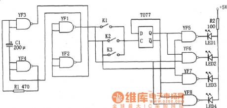
The above picture is a tap moving direction display circuit. The circuit is composed of micropulser, D trigger (T077), decoding circuit, and luminous diodes LED1~LED4 etc.
Micropulse iscomposed of 4 NAND gates from YF1 to YF4, with output signal frequency between 1 and 3 Hz. The frequency can be adjusted by changing the value of C1 and R1.Decoding circuit is composed of 4 NAND gates from YF5 to YF8. It’s output signal control the displaying of luminous diode, so that when the recorder works, light is given out from LED1 to LED4 in succession to indicate the direction the tape moves.
(View)
View full Circuit Diagram | Comments | Reading(649)
The 40-line medical use wireless calling system circuit
Published:2011/7/6 21:33:00 Author:qqtang | Keyword: medical use, wireless calling system
In figure 1 is one of the encoding emitter circuits, the system is equipped with 40 emitter circuit. In figure 2 is the reception display circuit. We divide the 40 codes into 4 teams, i.e 0, 1, 2 and 3 (only team 0 and 1 have drawn in figure 2). For the 10 codes 00~09 in team 0, all the address pins of the decoding circuit are suspended, when the receiver gets signals from an emitter of team 0, the signals are decoded by IC1 and encoded by IC5, and the corresponding indicator in LED00~LED09 are lit as memory.
(View)
View full Circuit Diagram | Comments | Reading(688)
The application circuit of 5-function remote control PT8A977/978
Published:2011/7/6 21:19:00 Author:qqtang | Keyword: application circuit, remote control
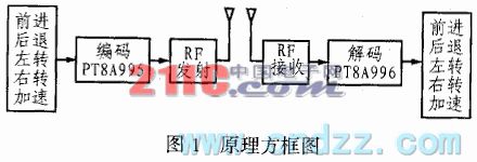
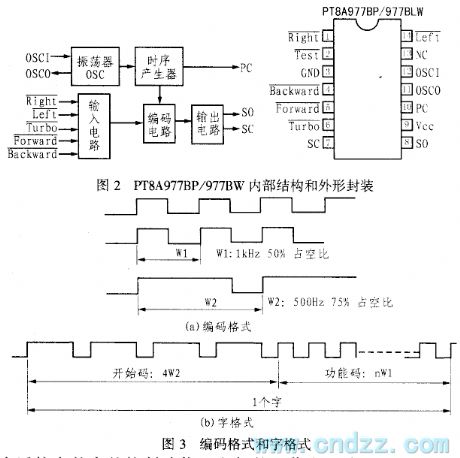
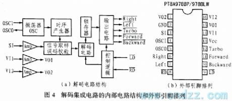
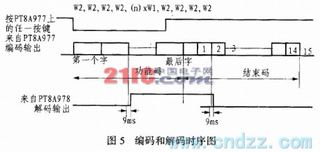
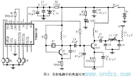
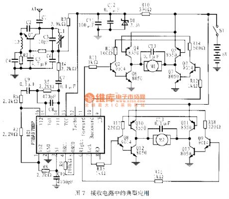
The remote toy car adopts the servo motor wireless remote control technology. The basic requirements of remote circuit design are good function, low cost, smooth operation, flexible control, simple wire, effective anti-disturbance, etc. Usually, the drive of the remote toy car needs 2 micro DC servo motors to complete the functions of heading forward, backing up, turning left, turning right and acceleration, etc. The toy car market is full of competition, so requirements on the electric function of them are higher and higher.
(View)
View full Circuit Diagram | Comments | Reading(3301)
The 6v,0.6w alarm flashing lamp circuit
Published:2011/7/6 21:01:00 Author:qqtang | Keyword: alarm flashing lamp
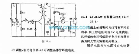
The 6v,0.6w alarm flashing lamp circuit(see as figure 26.4) The alarm lamps in traffic have different powers, whose working voltage can be provided by the 6V battery, such a lower voltage can be switched into the high voltage that the flash lamps need. The figured charge voltage can be regulated by the potentiometer R6, and the transistor peak value current can be regulated by potentiometer R3. (View)
View full Circuit Diagram | Comments | Reading(684)
The improved car steering alarm integrated application circuit of LZ1041
Published:2011/7/6 20:48:00 Author:qqtang | Keyword: steering alarm, application circuit
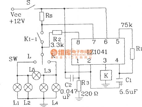
The improved car steering alarm integrated application circuit of LZ1041 (View)
View full Circuit Diagram | Comments | Reading(612)
Circuit Diagram of Electronic Guidepost Composed of 555 and CD4017
Published:2011/7/4 10:07:00 Author:Vicky | Keyword: Electronic Guidepost
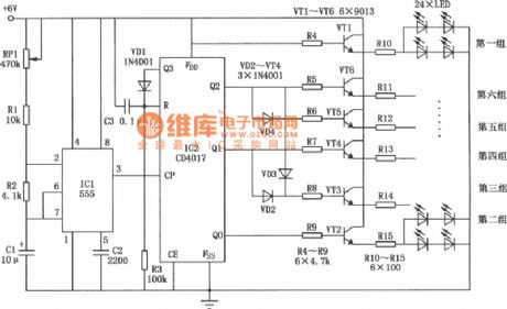
Electronic guidepost is shown as the picture. Its displaying circuit consists of 24 luminous diodes which are ranked in 6 groups in accordance with the direction of arrows. Electronic guidepost uses the pulse signal generated by time-base circuit to drive the 6 groups of luminous diodes to display dynamically according to a certain regular pattern so as to indicate the moving direction. The circuit is mainly composed of time-base circuit 555, decimal counter CD4017 and display circuit. (View)
View full Circuit Diagram | Comments | Reading(1125)
the sawtooth-wave circuit of complementary tube
Published:2011/6/30 6:11:00 Author:Fiona | Keyword: sawtooth-wave, complementary tube
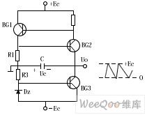
The picture shows the sawtooth-wave circuit of complementary tube.This is self-oscillating complementary sawtooth-wave circuit which the switching device is composed of BG1,BG2 and controls the timing capacitor C to charge and discharge,BG3 is constant flow pipe.When BG1, BG2 are closed, the constant current Ic3 charges to C(polarity is shown as the picture) the output voltage uo decreases with linear time, this is a scanning voltage positive process, when the capacitor voltage Uc drops to the BG2 conduction valve voltage, BG2 starts to conduct,BG1,BG2 arrive at the saturated state after a positive feedback chain reaction,at this time, when you reach a saturation point C remains at saturation without returning to the OFF state through BG1, BG2.
(View)
View full Circuit Diagram | Comments | Reading(725)
| Pages:1599/2234 At 2015811582158315841585158615871588158915901591159215931594159515961597159815991600Under 20 |
Circuit Categories
power supply circuit
Amplifier Circuit
Basic Circuit
LED and Light Circuit
Sensor Circuit
Signal Processing
Electrical Equipment Circuit
Control Circuit
Remote Control Circuit
A/D-D/A Converter Circuit
Audio Circuit
Measuring and Test Circuit
Communication Circuit
Computer-Related Circuit
555 Circuit
Automotive Circuit
Repairing Circuit