
Index 364
MCP component(MMl521XV) internal structure block diagram and its protection circuit
Published:2011/5/13 4:22:00 Author:Nicole | Keyword: component, internal structure
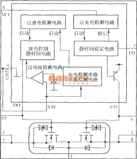
MCP is a multi- package produce which puts the integrated protection circuit and charge-discharge control into the same package. The internal structure block diagram is as below:
(View)
View full Circuit Diagram | Comments | Reading(552)
LM317T application circuit
Published:2011/5/13 4:17:00 Author:Nicole
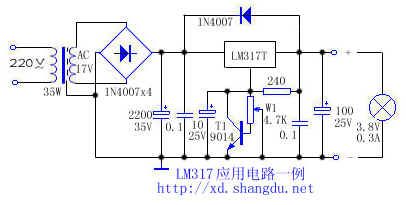
LM317T can be used to make adjustable regulated power supply, the load is often damaged due to the potentiometer's poor contact lead to voltage rise. If a triode is added(As shown in the figure), under normal circumstances, T1's base level is 0, T1 cuts off, it has no influence on circuit; when the W1 is poor contact, T1's base level rises, when it rises to 0.7V, T1 turns on, LM317T's adjustment terminal voltage drops, output voltage drops too, it can protect the load. If the triode is removed and the W1 middle point connecting line is cut off, 3.8V bulb will be burned down immediately, the output voltage reaches 21V. If it is added T1, the brightness of bulb will reduce, then LM317T output voltage is only 2V, it can effectively protect the load.
(View)
View full Circuit Diagram | Comments | Reading(1054)
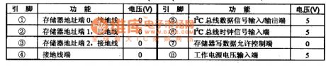
M24C08-MN6T-E(2)PROMAO~A7 storage integrated circuit diagram
Published:2011/5/16 2:53:00 Author:Nicole | Keyword: storage
M24C08-MN6T is a E(2)PROMAO~A7 storage integrated circuit which is produced by Mitsubishi Corp, it is widely used in all kinds of models and size large screen color television.
1. functions and features
M24C08-MN6T integrated circuit contains I square meter C bus circuit, memory address and storage singal control circuit and other assistant functions circuits.
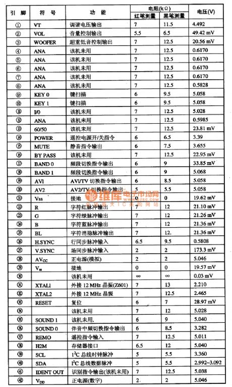
2. pin function and data
M24C08-MN6T integrated circuit adopts 8-foot dual in-line package, the pin function and data of this integrated circuit is shown in the table1.
Note: When M24C08-MN6T is used to different models, the writing process is different, so it can not bechanged directly.
(View)
View full Circuit Diagram | Comments | Reading(457)
Matrix Audio Switch Integrated Circuit
Published:2011/7/19 10:39:00 Author:Michel | Keyword: Switch Integrated Circuit
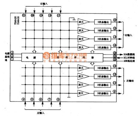
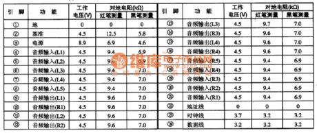
TEA6420 and TEA6430 are matrix audio switch integrated circuits produced by Thomson Company of France,which are widely used in the DLP projection TV, such as ChangHong 51PT28A DLP projection TV.
First,Function Features
TEA6420 and TEA6430 integrated circuit have five groups of stereo input, four groups of stereo output ends,gain control and mute control circuits, I(2)C bus decoder, power supply circuit and other auxiliary function circuit. Its intergrated block inside circuit block diagram is shown as picture 1-1.Picture 1 : Inside Circuit Block Diagram of TEA6420 and TEA6430 Intergrated Block
Second,Pins Functions and Data
TEA6420 and TEA6430 intergrated circuits use 24 feet DIP package and their pins functions and data are shown as table 1-2. (View)
View full Circuit Diagram | Comments | Reading(1501)
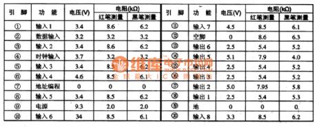
TEA6415C Matrix Video Switch Integrated Circuit
Published:2011/7/19 10:58:00 Author:Michel | Keyword: Video, Switch Integrated Circuit
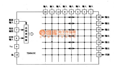
TEA6415C is matrix video switch integrated circuit produced by Thomson Company of France which is widely used in the DLP projection TV, such as ChangHong 5lPT28A etc.
First,Functions Features
The video switch circuit of TEA6415C integrated circuithas eight input and six the output ends. The switch function of intergrated block is controlled by I (2) C bus.And the block diagram is shown as
picture 1-1.
Second,Pins Functions and Data
TEA6415C IC adopts 20 feet DIP package and its pins functions and data are shown as table 1-2.
(View)
View full Circuit Diagram | Comments | Reading(1459)
Power Pupply, Starting and Ignition Circuit Principle Diagram of Liberation CA6400 Series Light Bus
Published:2011/7/19 9:34:00 Author:Michel | Keyword: Power Pupply, Starting, Ignition Circuit, Principle Diagram

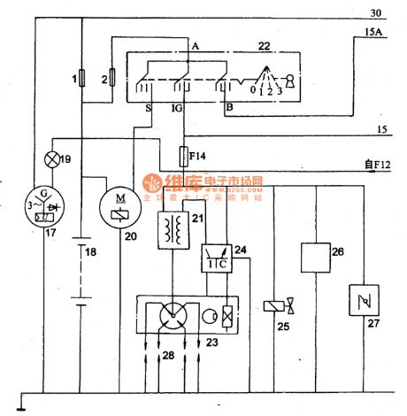
Picture: Power Pupply, Starting and Ignition Circuit Principle Diagram of Liberation CA6400 Series Light Bus
1·2一fusible line, 17一 integral ac generators,18一battery,19-rechargeable lights ,20-starter,21-ignition coil ,22-gnition switch,23-Hall type distributor ,24-ignition electronic device,25-idle block valves ,26-hot time valve ,27-automatic windshield door,28-spark plug.
(View)
View full Circuit Diagram | Comments | Reading(771)
TEA2025 Double Track Power Amplifier Integrated Circuit
Published:2011/7/19 11:35:00 Author:Michel | Keyword: Double Track, Power Amplifier, Integrated Circuit
TEA2025 is double track power amplifier integrated circuit manufactured in Europe.This circuit has a high track separation degree and the impact noise is small.The external devices are less and the biggest gain can be adjusted by external resistance.TEA2025 is used in pocket type or portable stereo system as power amplifier.
First,TEA2025 Inner Circuit Block Diagram and Pins Functions
TEA2025 block is composed of two same fucntions audio preplay ,power amplifier,drving circuit and power supply circuit.Its inner circuit block diagram and double track circuits are shown as picture 1-1.This IC uses 16 feet DIP package and integrated circuit pins functions and data are shown table 1-2.
Picture 1-1:Inner Circuit Block Diagram and Two Track Application Circuit of TEA2025 (View)
View full Circuit Diagram | Comments | Reading(842)
Signal Processing,Servo and Integrated Circuit of CXA1782BQ and CXA1782BR-RF
Published:2011/7/19 11:37:00 Author:Michel | Keyword: Signal Processing, Servo, Integrated Circuit
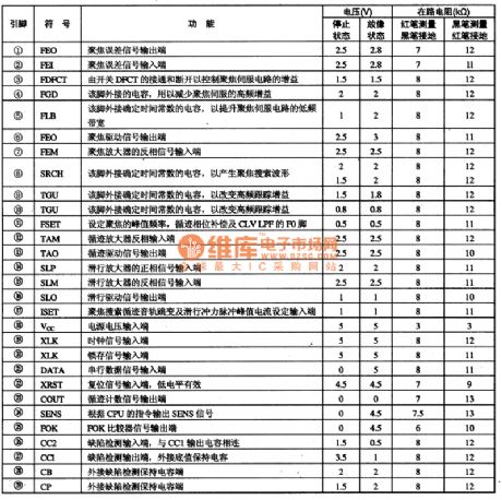
(View)
View full Circuit Diagram | Comments | Reading(564)
Three Colors Coding Integrated Circuit of CXA1645M VCD
Published:2011/7/19 10:13:00 Author:Michel | Keyword: Three Colors, Coding Integrated Circuit
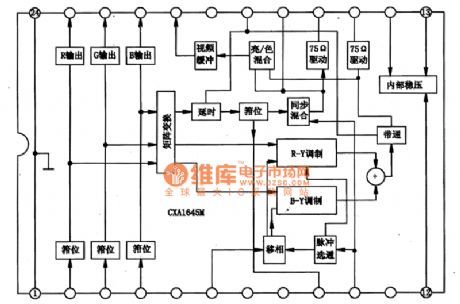
CXA1645M is three colors coding integrated circuit of VCD prodcued by SONY,which is widely used in SONY, Samsung and Sharp VCD.
First,Inner Circuit Block Diagram
CXA1645M internal includes color TV signal P/N coding system function and it can output video P/N system full TV signalor blue separation S terminal output signal as long as R, G, B three colors signal and composite synchronous pulse signal are input.The two kinds of output in IC internal have buffer amplifier and the best load is 75 Ω. CXA1645M internal does not set color coding of special color subcarrier oscillator.The special negative carrier generating circuit is used when it is used in the VCD. (View)
View full Circuit Diagram | Comments | Reading(1546)
Q adjustable notching filter circuit
Published:2011/7/17 2:03:00 Author:Fiona | Keyword: notching filter
Q adjustable notching filter circuit is shown as above:
(View)
View full Circuit Diagram | Comments | Reading(705)
polarity detector of absolute value amplifier circuit
Published:2011/7/17 23:50:00 Author:Fiona | Keyword: absolute value amplifier, polarity detector
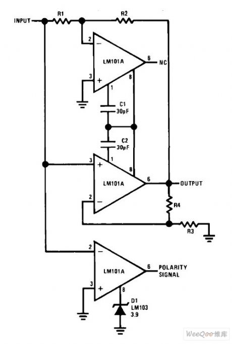
Polarity detector of absolute value amplifier circuit is shown as above:
(View)
View full Circuit Diagram | Comments | Reading(1053)
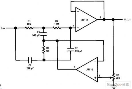
Low input current circuit that quick summary of the amplifier
Published:2011/7/17 23:01:00 Author:Fiona | Keyword: quick summary of the amplifier
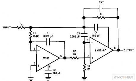
Low input current circuit that quick summary of the amplifier is shown as above: (View)
View full Circuit Diagram | Comments | Reading(648)
Ultra low working voltage white LED drive circuit
Published:2011/7/17 2:24:00 Author:Fiona | Keyword: drive, Ultra low working voltage

Ultra low working voltage white LED drive circuit is shown as above:
(View)
View full Circuit Diagram | Comments | Reading(599)
The thermometer composed of diode temperature sensors
Published:2011/7/17 20:01:00 Author:Borg | Keyword: thermometer, temperature sensors
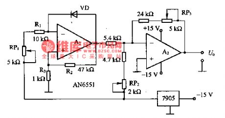
This is the thermometer composed of diode temperature sensors. In the circuit, R1 and RP1 make VD have a constant current of 0.5mA, R2 and R3 are both the forward feedback resistors, which make the linearity under 2%. In the temperature range of -20-+5O℃, the output sensitivity of A1 is -2OmV/℃. By adjusting RP2, when it is O℃, A2 outputs a voltage of 0V. If the gain of A2 is set to be 5 times, the sensitivity will be 0.1v/℃, which can be connected with the digital multi-meter, so the temperature under test can be read out directly.
(View)
View full Circuit Diagram | Comments | Reading(1338)
The warm air sensor circuit composed of LM334
Published:2011/7/17 22:24:00 Author:Borg | Keyword: warm air, sensor
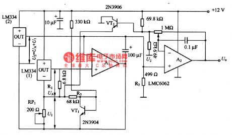
In the figure is the warm air sensor circuit composed of LM334. LM334(2) is used to test the warm air temperature (Ts); LM334(1) is used to the outside temperature (TA). LM334 sensor is to converter the 1K thermodynamics temperature into the 214μV voltage, so if the voltage difference of (Us-UA) is tested, the temperature difference of (Ts-TA) can be got. The voltage U1 and UA can be got by the circuit composed of RP1, R3 and VT1, and US=UA+Ul, therefore, TS=TA+TI (i.e Ul/2l4μV). (Ts-TA) is set by RP1.
(View)
View full Circuit Diagram | Comments | Reading(1319)
P83C266BDR Single-chip Microcomputer Integrated Circuit
Published:2011/7/17 6:32:00 Author:Michel | Keyword: Microcomputer Integrated Circuit
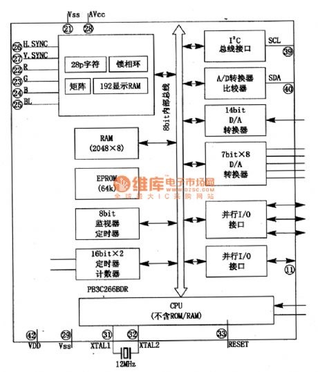
P83C266BDR is latest eight high speed digital CMOS central microcomputer monolithic integrated circuit prdoduced by Philips.It is designed for Konka series mirror TVs, such as P3486C type machine etc.
First,Fucntions
P83C266BDR integrated circuit contains the central microprocessor (CPU), electric programmable read-only memory (an EPROM), random access memory (RAM), input and output interface (I/O), l6 bit timer/counter, A/D and D/A, OSD generator, the I2C bus SCL, SDA serial interface and pulse width modulation (PWM) circuit components etc.The inside circuit of the intergrated block is shown as picture 1.
Picture 1:The Inside Circuit of Intergrated Circuit (View)
View full Circuit Diagram | Comments | Reading(903)
The Output Circuit-32V Linear Regulating Circuit
Published:2011/7/17 10:16:00 Author:Michel | Keyword: Linear Regulating Circuit
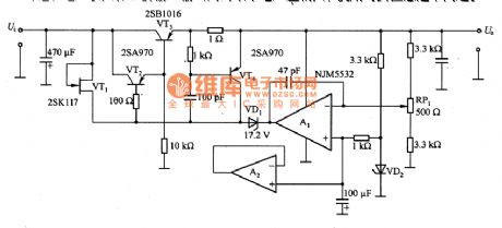
The picture is output circuit-32V linear regulating circuit.And its output current is 500mA.In the circuit,RP1 is used to adjust the output voltage.VT1 can choose 2SK30A field effiency tube and here 2SK117 is used.2SK117 saturated voltage is large thus the minimum current difference between the output and input is a little large and this problem should be noticed when we use it. (View)
View full Circuit Diagram | Comments | Reading(606)
Charger Circuit of BP2002
Published:2011/7/16 10:18:00 Author:Michel | Keyword: Charger Circuit
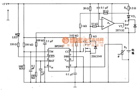
Picture 9 is charger circuit of BP2002.When the longest charging time is 160 minutes,the timer acts.Thermistors RT is used to test the temperature of the battery charging and it is close to the surface of charging batteries. When the temperature of the battery is 60 ℃,the battery stops charging.When it is fast charging, the current flows through the Rs is 490 mA. It produces 98 mV voltage drop and produces 0.2V voltage drop on VD1.After fast charging,it compensates for the charging for 16O minutes and then it continuously supplements the charging in C/64 rate. (View)
View full Circuit Diagram | Comments | Reading(623)
Charger Circuit of LM317
Published:2011/7/16 11:03:00 Author:Michel | Keyword: Charger Circuit
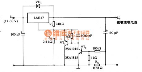
The above picture is charger picture of LM317.It adopts LM317 constant current to charge and its input voltage Ui is +17~+30V and the output voltage is U.The largest voltage is 3.8V and largest current is 1A.The output voltage is same with termination voltage of charged battery,they are set by dividing resistor R1 and R2.RS tests output current and VT1 and automatically adjust the LM317,thus output voltage is consistent with battery terminal voltage.And it outputs constant current which is about 1 A.RS resistance obeys the following formula, namely RS = UBE / 1 A = 0.7 V / 1 A ≈ 0.7 Ω and it chooses 0.68Ω in the circuit (View)
View full Circuit Diagram | Comments | Reading(3006)
Regulated Power Supply Circuit with 42V/500mA Output
Published:2011/7/16 22:40:00 Author:Michel | Keyword: 42V/500mA Output, Regulated Power Supply Circuit
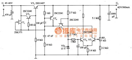
The above picture is regulated power supply Circuit with 42V/500mA output.In the circuit, VT1 adopts UDS = 1 of OOV mosfet 2 SK373 to constitute a high voltage constant current source.Besides the field effect tube,constant current diode E-202 is also avaliable.Largest work voltage of E-202 is 1OOV and its rated power is 3 OmW.VT6 and VT7are error amplifiers and they use the UcEo. 2SC2240 is 12OV high pressure transistor and VT5 constitutes cascode amplifier to improve frequency characteristics of the error amp. (View)
View full Circuit Diagram | Comments | Reading(1417)
| Pages:364/471 At 20361362363364365366367368369370371372373374375376377378379380Under 20 |
Circuit Categories
power supply circuit
Amplifier Circuit
Basic Circuit
LED and Light Circuit
Sensor Circuit
Signal Processing
Electrical Equipment Circuit
Control Circuit
Remote Control Circuit
A/D-D/A Converter Circuit
Audio Circuit
Measuring and Test Circuit
Communication Circuit
Computer-Related Circuit
555 Circuit
Automotive Circuit
Repairing Circuit