
Index 176
DARLINGTON_TRANSISTOR_OSCILLATOR
Published:2009/6/23 2:23:00 Author:Jessie
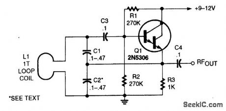
This oscillator uses a very large capacitance-to-inductance ratio. L1 is a one-tum coil consisting of a loop of #12 wire 12 in diameter. This circuit is useful for metal detectors, etc., where a loop antenna is used. (View)
View full Circuit Diagram | Comments | Reading(4875)
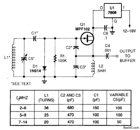
HF_VFO_CIRCUIT
Published:2009/6/23 2:22:00 Author:Jessie
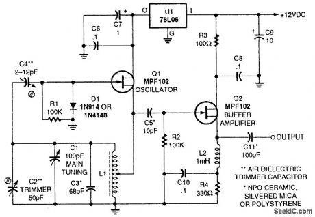
This typical HF VFO circuit has several stability-enhancing features, including well-chosen capacitor types. The frequency of the VFO is approximately 2π (C1 + C2 + C3) L1. L1 should be an aircore type coil, rigidly mounted, with high (>200 value) value of Q. (View)
View full Circuit Diagram | Comments | Reading(3753)
CAPACITOR_HYSTERESIS_COMPENSATOR
Published:2009/6/23 2:22:00 Author:Jessie

View full Circuit Diagram | Comments | Reading(1167)
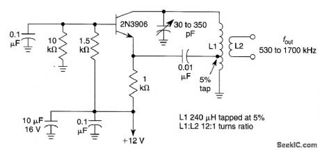
GROUNDED_BASE_TUNED_COLLECTOR_OSCILLATOR_FOR_AM_BROADCAST_BAND
Published:2009/6/23 2:20:00 Author:Jessie
View full Circuit Diagram | Comments | Reading(1345)
REINARTZ_OSCILLATOR
Published:2009/6/23 2:09:00 Author:Jessie
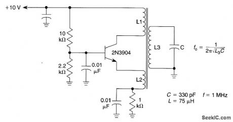
This oscillator uses mauctivity coupled emitter and collector windings to its main tank circuit.Take care so that L1 and L2 are not coupled to each other, otherwise this circuit is susceptible to parasitic at other frequencies.Typically ,L1 has 5 to 10 times the number of turns that L2 has.L1,L2,L3 are woundon same coil form. This oscillator is more suited to lower frequencies,≤10 MHz. (View)
View full Circuit Diagram | Comments | Reading(1951)
PSEUDO_RANDOM_BIT_SEQUENCE_GENERATOR
Published:2009/6/23 2:09:00 Author:Jessie
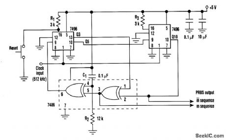
In this circuit, an additional exclusive-OR gate is connected after the modulo-2 feedback, with C1 and R2 applying the supply turn-on ramp into the feedback loop. This provides sufficient transient signal so that the PRBS generator can self-start a power-up. A shift-register length n of 10 is shown with feedback at stages 3 and 10, providing true and inverted maximal length sequence outputs.
This technique applies an input directly to the feedback loop. Therefore, it's considered more reliable than applying an RC configuratior) to the shift-register reset input to create a random turnon state. (View)
View full Circuit Diagram | Comments | Reading(3886)
AM_OSCILLATOR_FOR_WIRELESS_MICROPHONES
Published:2009/6/23 2:05:00 Author:Jessie
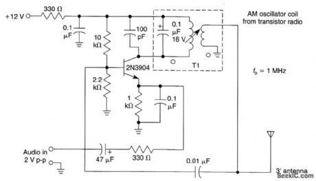
This circuit will generate an AM-modulated signal in the AM broadcast band that can be picked up on a receiver.About 2V of audio input will produce about 30% modulation of the oscillator signal.An old AM broadcast oscillator coil or other two-winding coil with about a 10:1 turn ratio and about 50 to 150 μH inductance can be used for T1. (View)
View full Circuit Diagram | Comments | Reading(1498)
JFET_VARIABLE_FREQUENCY_OSCILLATOR
Published:2009/6/23 2:01:00 Author:Jessie
This simple JFET-based variable-frequency oscillator can be used in receiver and transmitter circuits. (View)
View full Circuit Diagram | Comments | Reading(8048)
STABILIZED_WIEN_BRIDGE_OSCILLATOR
Published:2009/6/23 1:50:00 Author:Jessie
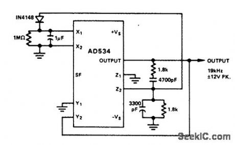
In this application, the AD534 is used as a vari-able-gain amplifier for the feedback signal from the output to the Y input, via the Wien bridge. The peak-rectifter and filter combination applies sufficient voltage to the X (denominator) input to maintain a stable oscillation-amplitude (with about 0.2% ripple). At startup, because X is small (divider mode), the gain is high, and the oscillation builds up rapidly. This is but one of several possible schemes, involving no extemal active elerrtents. Its forte is simplicity, rather than high performance; nevertheless, the amplitude is not greatly affected by supply and temperature variations, about 0.003 dB per volt, and 0.005 dB per degree. (View)
View full Circuit Diagram | Comments | Reading(1873)
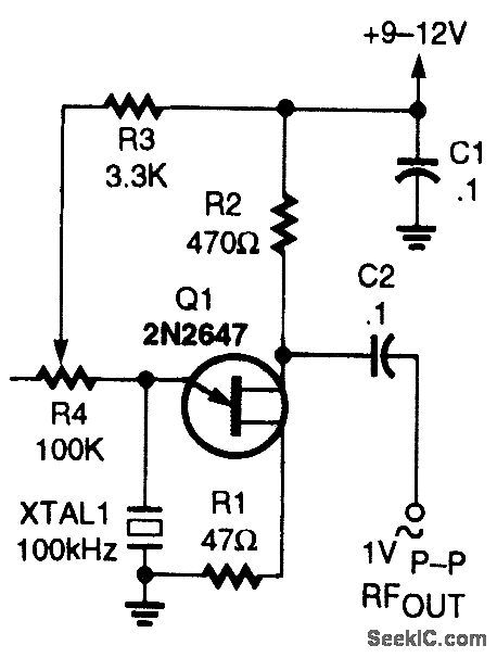
UJT_100_kHz_CALIBRATION_OSCILLATOR
Published:2009/6/23 1:49:00 Author:Jessie
This unusual 100-kHz oscillator (whose fre-quency is determined by XTALl) can be used as a marker generator to calibrate the analog diai of a communication receiver, or its output can be fed to a divider courtter to produce a stable lower-fre-quency output for use as a clock-signal generator. (View)
View full Circuit Diagram | Comments | Reading(2026)
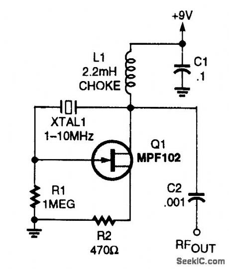
FET_VXO_CIRCUIT
Published:2009/6/23 1:49:00 Author:Jessie
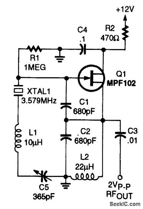
An MPF 102 is used in a Colpitts-type oscilla-tor in order to pull the crystal frequency slightly. (View)
View full Circuit Diagram | Comments | Reading(2025)
dc_OUTPUT_CHOPPER
Published:2009/6/23 1:49:00 Author:Jessie
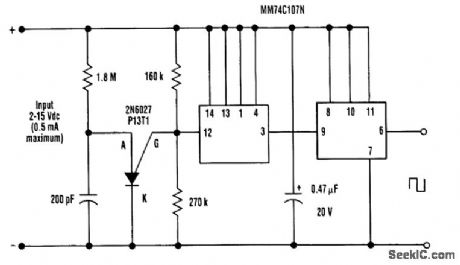
Any dc voltage source in the 2- to 15-V range can be chopped into a unipolar square wave that has a peak amplitude nearly equal to the dc source voltage with circuit (lightly loaded CMOS will swing within a few millivolts of each rail at low frequencies). Depending on the actual voltage of the supply, the programmable-unij unction-transist or (PUT) relaxation oscillator produces 2000-Hz trigger pulses. These pulses operate the cascaded 74C107 flip-flop, producing a square wave. (View)
View full Circuit Diagram | Comments | Reading(1503)
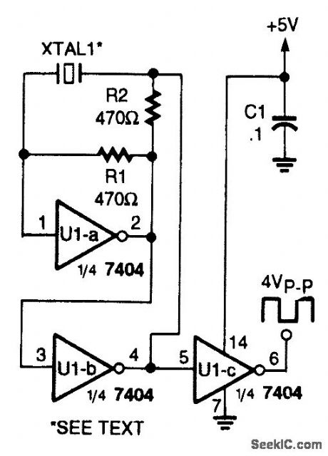
CRYSTAL_OSCILLATOR_I
Published:2009/6/23 1:49:00 Author:Jessie
In this circuit, series-resonant crystal XTAL1 is used as a frequency-determining element.XTAL1 is between 0.1 to 10 MHz. (View)
View full Circuit Diagram | Comments | Reading(1278)
QUADRATURE_WAVE_OSCILLATOR
Published:2009/6/23 1:49:00 Author:Jessie
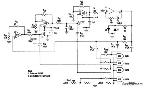


By using a high-frequency quad current-feedback amplifier (the HA5025) as an RC oscillator, four quadrature sine waves can be generated. The HA5025's four separate amplifiers generate the sine waves, and the quad NAND gate, U2, is biased at its threshold, so it acts as a sine-wave to square-wave converter when the she waves are ac coupled into its input. (View)
View full Circuit Diagram | Comments | Reading(1385)
FET_QUARTZ_CRYSTAL_OSCILLATOR
Published:2009/6/23 1:48:00 Author:Jessie
This oscillator uses an MPF102 JFET as an active element. (View)
View full Circuit Diagram | Comments | Reading(4451)
VARIABLE_FREQUENCY_ASTABLE_II
Published:2009/6/23 1:43:00 Author:Jessie
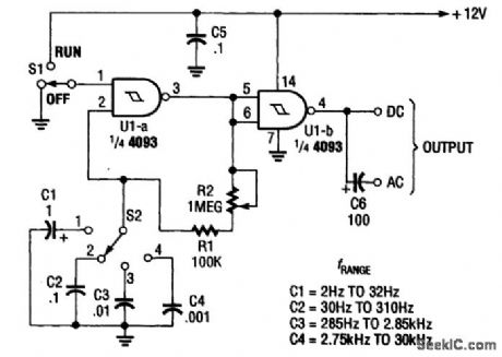
This circuit uses a single potentiometer and switched capacitors to cover 2 Hz to 30 kHz。 (View)
View full Circuit Diagram | Comments | Reading(1511)
ASTABLE_OSCILLATOR_II
Published:2009/6/23 1:43:00 Author:Jessie
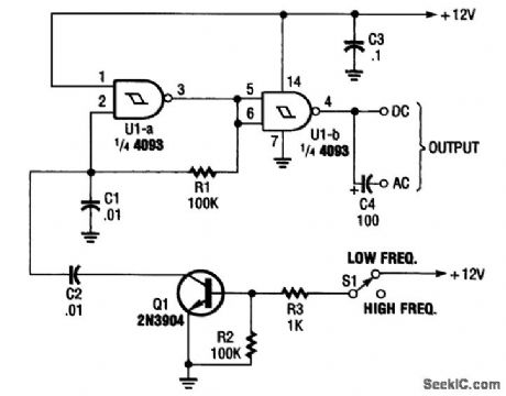
By using transistor switch Q1/R2/R3, the frequency of an astable oscillator can be changed with a dc voltage or logic level. (View)
View full Circuit Diagram | Comments | Reading(1410)
ASTABLE_OSCILLATORI
Published:2009/6/23 1:41:00 Author:Jessie
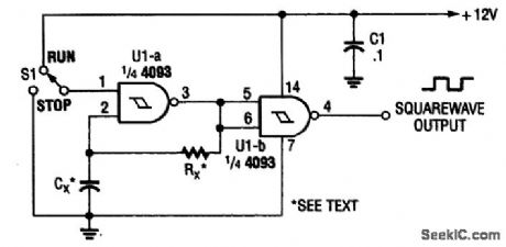


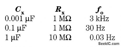
In this circuit,two gates from the quad 4093 package are used to form a simple astable squarewave oscillator.The values for RX and CX are approximately as follows∶These values can be scaled for other frequencies. (View)
View full Circuit Diagram | Comments | Reading(2754)
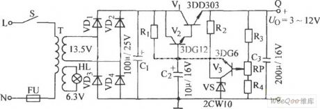
Simple Series Adjustable Regulator Circuit
Published:2011/7/18 5:26:00 Author:Felicity | Keyword: Simple Series Adjustable, Regulator Circuit
View full Circuit Diagram | Comments | Reading(667)
The low-noise and high-efficiency PWM step-down converting power supply circuit
Published:2011/7/24 3:29:00 Author:Seven | Keyword: low-noise, high-efficiency, power supply
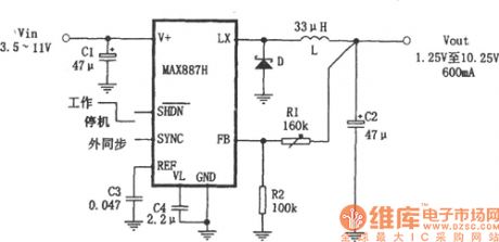
In the figure is the adjustable step-down power supply which is based on the low-noise and high-efficiency PWM converter MAX887(8-SO package), and the external elements are few. The characters of it are: (1) the input voltage is from 3.5V to 11.5V, the output voltage is 1.25V to 10.25V; (2) the output current is 600mA, and the static current is 200μA, the standby mode is only 2.5μA; (3) the converting efficiency is 95%; (4) the fixed working frequency of MAX887 is 300KHZ, which effectively reduces the size and cost of the external element.
(View)
View full Circuit Diagram | Comments | Reading(617)
| Pages:176/291 At 20161162163164165166167168169170171172173174175176177178179180Under 20 |
Circuit Categories
power supply circuit
Amplifier Circuit
Basic Circuit
LED and Light Circuit
Sensor Circuit
Signal Processing
Electrical Equipment Circuit
Control Circuit
Remote Control Circuit
A/D-D/A Converter Circuit
Audio Circuit
Measuring and Test Circuit
Communication Circuit
Computer-Related Circuit
555 Circuit
Automotive Circuit
Repairing Circuit