
Index 169
SIMPLE_VOLTAGE_PROBE
Published:2009/6/26 5:31:00 Author:May
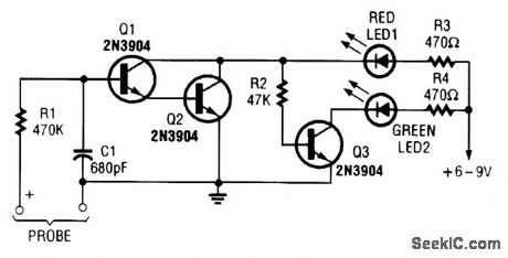
This simple voltage probe can be helpful in checking and troubleshooting solid-state circuitry. (View)
View full Circuit Diagram | Comments | Reading(1086)
±5_TO±35_V_TRACKING_POWER_SUPPLY
Published:2009/6/26 5:04:00 Author:May
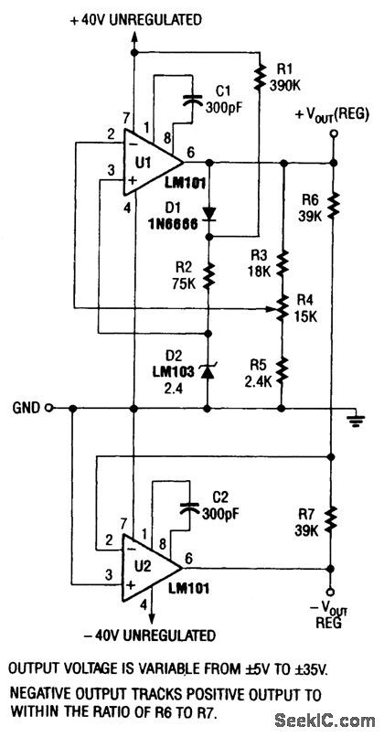
This supply is designed to operate from a ±40V nominal unregulated power source (bridge rectifier, etc.). (View)
View full Circuit Diagram | Comments | Reading(705)
DUAL_AUDIO_AMPLIFIER_POWER_SUPPLY
Published:2009/6/26 4:30:00 Author:May
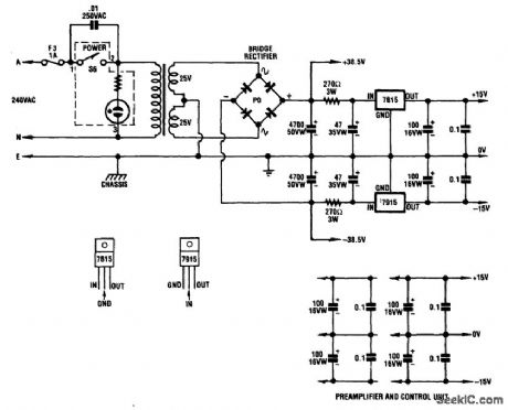
A dual audio amplifier that will deliver 50 W per channel is shown in the schematic. It includes preamp and tone controls, and also includes a headphone amplifier. The circuit depicts the power supply that supplies ±38.5 V and ±15 V regulated for the dual 50 watter. (View)
View full Circuit Diagram | Comments | Reading(2329)
SUBWOOFER_AMPLIFIER_POWER_SUPPLY
Published:2009/6/26 4:26:00 Author:May
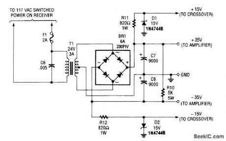
Although intended to power a 100-W low-frequency amplifier, this power supply should handle many mono or stereo amplifiers in the medium power range that require ±30 to 35 V. (View)
View full Circuit Diagram | Comments | Reading(924)
TELECOM_CONVERTER_-48_V_TO_5_V@1_A
Published:2009/6/26 5:29:00 Author:Jessie

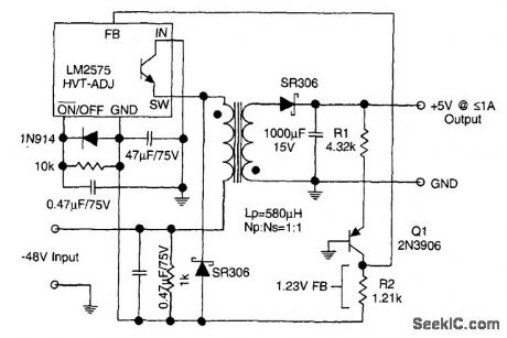
The circuit supplies 1 A at +5 V from the -48-V supply commonly used in telephone equipment. The National Semiconductor LM2575 is a simple switching regulator. (View)
View full Circuit Diagram | Comments | Reading(1246)
ADD_12_V_OUTPUT_TO_5_v_BUCK_REGULATOR
Published:2009/6/26 5:27:00 Author:Jessie
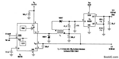
By adding a flyback winding to a buck-regulator switching converter (see the figure), which is essentially a 5-V supply with a 200-mA output capability, a 12-V output (VPP) can be produced. The flyback winding on the main inductor (forming transformer T1) enables an additional low-dropout linear regulator (IC2) to create the 12-V output voltage that's needed to program EEPROMs. The required input voltage is 8 to 16 V. (View)
View full Circuit Diagram | Comments | Reading(775)
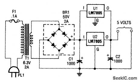
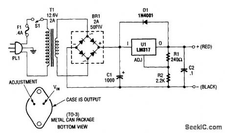
_5_V_SUPPLY
Published:2009/6/26 5:24:00 Author:Jessie

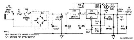
The power supply shown is designed to operate from a wall transformer. This circuit can be used in conjunction with a variable supply to test circuits in the lab, etc. T2 is a 12-V wall transformer. (View)
View full Circuit Diagram | Comments | Reading(751)
5_V_UPS
Published:2009/6/26 5:22:00 Author:Jessie
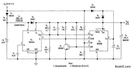
A 9-V wall adapter supplies VIN. IC2 contains a low-battery detector circuit that senses VIN by means of R6 and R7. The detector output (pin 7) drives an inverter (Q1), which in tum drives the shut-down inputs IC of IC1 and SHDN of IC2. These inputs have opposite-polarity active levels. The common feedback resistors, R2 and R3 enable both regulators to sense the output voltage, VOUT.
When IC2 shuts down, its output turns off. However, when IC1 shuts down, the whole chip assumes a low-power state and draws under 1 μA. L1, D2, C1, C2, R2, and R3 are part of the 250-mW switching regulator. Diodes D3 and D4 wire-OR the power connection to IC2, and C3 improves the linear regulator's load regulation. (View)
View full Circuit Diagram | Comments | Reading(1726)
INEXPENSIVE_ISOLATION_TRANSFORMERIMPROMPTU_SETUP
Published:2009/6/26 5:17:00 Author:Jessie
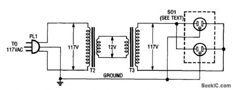
Using two 12-V filament or power transformers, an impromptu isolation transformer can be made for low-power(under 50 W) use in testing or servicing. SO1 is an ordinary, duplex ac receptable. Use heavy-wire connections between the 12-V windings because several amperes can flow. (View)
View full Circuit Diagram | Comments | Reading(3376)
ANTIQUE_RADIO_dc_FILAMENT_SUPPLY
Published:2009/6/26 5:11:00 Author:Jessie
This dc supply is great for operattng battery-powered anuque radios, because it is designed to prevent harming the tube filaments. The circuit is useful for powenng filaments of 00-A, 01-A, 112A,and 71A tubes, which requlre 5V at 250 mA. (View)
View full Circuit Diagram | Comments | Reading(962)
_15_V_SUPPLY_FOR_ZN416E_CIRCUITS
Published:2009/6/26 5:07:00 Author:Jessie
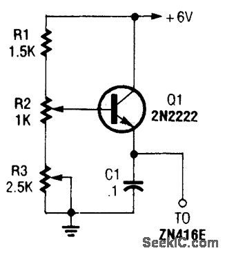
This regulator can be used with a +6-V source to supply ZN416E low-voltage TRF radio-receiver IC the necessary +1.5 V. R3 sets output voltage. (View)
View full Circuit Diagram | Comments | Reading(678)
8_V_FROM_5_V_REGULATOR
Published:2009/6/26 5:05:00 Author:Jessie

If you have trouble locating an 8-V regulator, although they are commonly available, a 5-V unit can replace it by connecting the regulator, as is shown here. (View)
View full Circuit Diagram | Comments | Reading(1035)
ADJUSTABLE_20_V_SUPPLY
Published:2009/6/26 3:59:00 Author:May
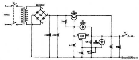
This circuit can deliver 3 A or more and a maximum dc voltage of a little over 20 V. It is designed around the readily available LM317T adjustable 3-terminal regulator and has a pnp power transistor to boost the current output.
The transformer has an 18-V secondary rated at 6 A; this feeds to bridge rectifier and two 4700-μF capacitors to yield around 25 Vdc. This voltage is fed to the emitter of the MJ2955 transistor and to the input of the LM317 via a 33-Ω resistor. (View)
View full Circuit Diagram | Comments | Reading(2004)
LAPTOP_COMPUTER_POWER_SUPPLY
Published:2009/6/26 4:13:00 Author:Jessie
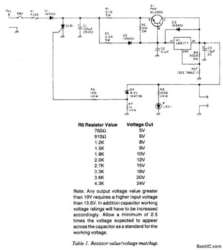
A laptop computer supply that has 9-V output, crowbar overvoltage protection, and operates from a 12-V supply is shown above. The supply voltage should be at least 3.6 V above the expected output voltage. Q1 should be heatsinked appropriately.R5 should have a value of 1.5 kΩ for 9-V out-put. Table 1 gives values for other voltages. (View)
View full Circuit Diagram | Comments | Reading(980)
0_TO_12_V,_1_A_VARIABLE_POWER_SUPPLY
Published:2009/6/26 3:55:00 Author:May
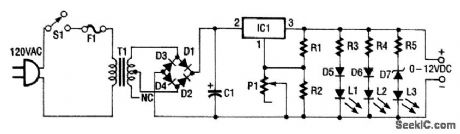
This 0- to 12-Vdc variable power supply uses an IC voltage regulator and a heavy-duty trans-former to provide a reliable dc power supply. Looking at the schematic shown, you can see that transformer T1 has a 120-V primary and a 28-V secondary.
Filtered dc is fed to the input (pin 2) ofthe LM317T voltage regulator, IC, which keeps the volt-age at its output constant (pin 3) regardless (within limitations) of the input voltage. Pin 1 of the LM317T is the adjustment pin. Varying the voltage on pin 1 (via P1) varies the output voltage.
Diodes D5 through D7 and LEDs L1 through L3 give an approximate indication of the output voltage. Each LED/diode path has a limiting resistor to limit the current to a level that is safe for the LED. (View)
View full Circuit Diagram | Comments | Reading(1273)
138_Vdc_2_A_REGULATED_POWER_SUPPLY
Published:2009/6/26 3:53:00 Author:May
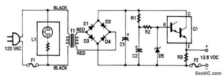
This regulated power supply consists of step-down transformer T1, a full-wave rectifier bridge (D1 through D4), and a filtering regulator circuit made up of C1, C2, R1, R2, R3, D5, and Q1. When 120 Vac is provided, the neon-lamp assembly L1 lights up, and transformer T1 changes 120 Vac to about 28 Vac. The rectifier bridge, D1 through D4, rectifies the ac into pulsating dc, which is then fil-tered by C1. Capacitor C1 acts as a storage capacitor. Zener diode D5 keeps the voltage constant across the base of Darlington regulator Q1, causing constant voltage across resistor R3 and the (+) and (-) output terminals, where the load is connected. Fuse F2 is used to open ( blow ), if the cur-rent through the output terminals is too high. Make sure to take proper precautions when using projects powered by 120 Vac. (View)
View full Circuit Diagram | Comments | Reading(1160)
24_V_TO_33_V_SWITCHING_REGULATOR
Published:2009/6/26 4:08:00 Author:Jessie
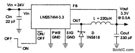
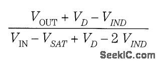
The National Semiconductor LM2574 delivers 3.3 V out at O.SAfrom a 24-V source. The duty cycle is:VD = diode drop(0.39)VIND = inductor dc dropVSAT = saturation voltage of LM2574(0.9 V typical) (View)
View full Circuit Diagram | Comments | Reading(1337)
5_V_TO_33_V_SWITCHING_REGULATOR
Published:2009/6/26 4:05:00 Author:Jessie
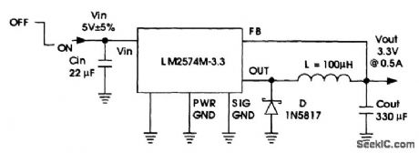
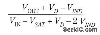
A National Semiconductor LM2574 is used to derive 3.3 V at 0.5 A from a 5-V logic bus. The duty cycle is: VD = diode drop (0.39) VIND = inductor dc drop VSAT = saturation voltage of LM2574 (0.9 V typical) This circuit should be useful to derive 3.3 V for logic devices from existing +5-V buses. (View)
View full Circuit Diagram | Comments | Reading(1237)
HV_POWER_SUPPLY_WITH_9_TO_15_Vdc_INPUT_
Published:2009/6/26 3:38:00 Author:May
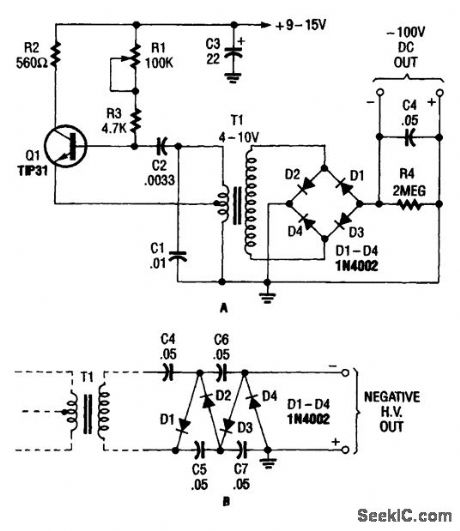
The combination Hartley oscillator/step-up transformer shown in A can generate significant negative high voltage, especially if the voltage output of the transformer is multiplied by the circuit in B. (View)
View full Circuit Diagram | Comments | Reading(709)
CONFIGURABLE_POWER_SUPPLY
Published:2009/6/26 3:18:00 Author:May
The adjustable supply can easily be reconfigured by altering the value of V2 and beefing up some other components, as is necessary.
The output voltage is given by VOUT = 1.25 (1 + R2/R1) . R2 can be chanced, as is necessary. (View)
View full Circuit Diagram | Comments | Reading(682)
| Pages:169/291 At 20161162163164165166167168169170171172173174175176177178179180Under 20 |
Circuit Categories
power supply circuit
Amplifier Circuit
Basic Circuit
LED and Light Circuit
Sensor Circuit
Signal Processing
Electrical Equipment Circuit
Control Circuit
Remote Control Circuit
A/D-D/A Converter Circuit
Audio Circuit
Measuring and Test Circuit
Communication Circuit
Computer-Related Circuit
555 Circuit
Automotive Circuit
Repairing Circuit