
Index 173
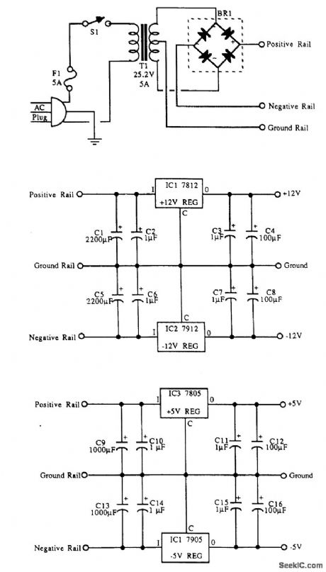
QUAD_POWER_SUPPLY
Published:2009/6/24 2:01:00 Author:May
View full Circuit Diagram | Comments | Reading(1266)
EXPERIMENTER’s_POWER_SUPPLY
Published:2009/6/24 2:00:00 Author:May
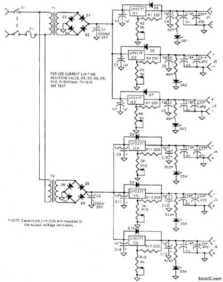
Passive linear IC regulators are used to make up a supply delivering +12, +9, +5, -5, -9, and -12 Vdc. T1 and T2 are 12-V, 3-A transformers. (View)
View full Circuit Diagram | Comments | Reading(595)
PULSE_WIDTH_MODULATED_LASER_SUPPLY
Published:2009/6/24 1:57:00 Author:May
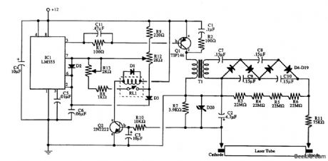
IC1 initially provides drive for Q1 and HV transformer T1, and it rectifies D4 through D19. When the laser tube ignites, Q2 is triggered; this activates relay RL1, reducing the duty cycle. R13 controls the duty cycle of the pulses through the laser tube. (View)
View full Circuit Diagram | Comments | Reading(774)
__HIGH_VOLTAGE_TRIPLEN
Published:2009/6/24 1:53:00 Author:May
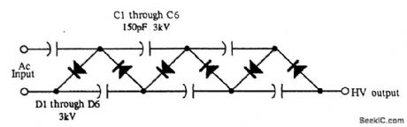
This tripler is useful for low-current and high-voltage applications.The capacitors can be 0.001-μF,3- to 6-kV discs,and the diode's 3-kV units,or three each IN4007 in series. (View)
View full Circuit Diagram | Comments | Reading(814)
KIRLIAN_DEVICE_SUPPLY
Published:2009/6/24 1:50:00 Author:May

This device is essentially a high-voltage variable-frequency ac supply.A CD4049 IC multivibrator circuit drives a darlington connected transistor pair,which drives TR2,an HV transformer. (View)
View full Circuit Diagram | Comments | Reading(2137)
ac_OPERATED_HE_NE_POWER_SUPPLY
Published:2009/6/24 1:43:00 Author:May
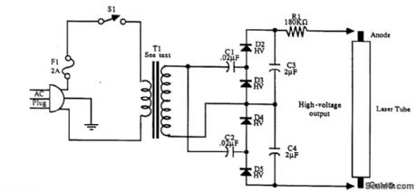
T1 is a 120-V to 1000-V step-up 60-Hz transformer. C1, C2, C3, C4 and D2 through D5 form a voltage quadruplet. The initial voltage is 4 to 5 kV, which drops when the laser tube fires. (View)
View full Circuit Diagram | Comments | Reading(585)
NIGHT_VISION_SCOPE_POWER_SUPPLY
Published:2009/6/24 1:38:00 Author:May
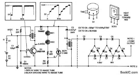
This high-voltage power supply has an inverter around Q1 that supplies 150-V pulses to the converter of SCR1 and C2. The output of T2 is a 4.5-kV pulse that is multiplied by the voltage-tripler network (right) to produce 13.5 kV.
T1 is a 3-kΩ to 500-Ω CT transistor audio transformer, T2 is a flash tube trigger transformer with a 6-kV secondary. (View)
View full Circuit Diagram | Comments | Reading(3240)
FLUORESCENT_LAMP_12_V_SUPPLY
Published:2009/6/24 1:34:00 Author:Jessie
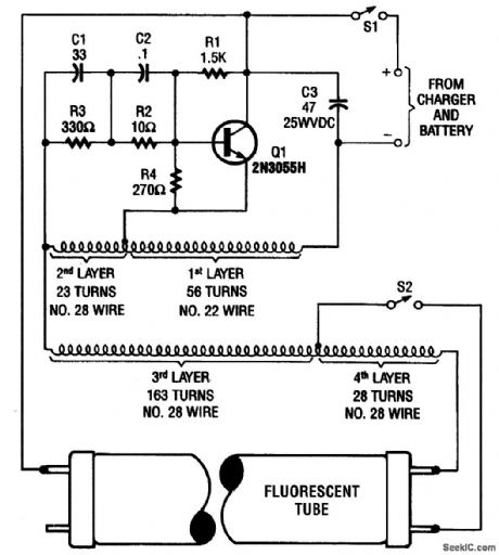
This high-voltage power supply can operate fluorescent tubes from a 12-V source, even if the tube has a defective filament. It essentially is an oscillator that excites a home-made autotransformer. T1 is wound on a ferrite rod 5/16 diameter by 1 7/8 long, in layers. S2 is an optional lamp filament switch. (View)
View full Circuit Diagram | Comments | Reading(1050)
5_A_CONSTANT_VOLTAGE_SUPPLY
Published:2009/6/23 4:51:00 Author:May
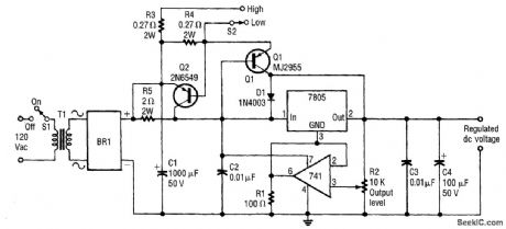
This constant-voltage supply has a variable output.It can supply more than 5 A, and has two switchable current limits. (View)
View full Circuit Diagram | Comments | Reading(842)
TELEPRINTER_LOOP_SUPPLY
Published:2009/6/23 4:50:00 Author:May
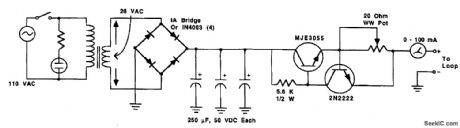
A circuit to power a teleprinter, using transistors as current-controlling devices. The power supply used provides a constant current in a loop, normally 60mA or 20 mA, depending on the machine. (View)
View full Circuit Diagram | Comments | Reading(627)
Flyback Synchronous Rectifier Control Circuit of Adapter
Published:2011/7/13 7:51:00 Author:Michel | Keyword: Synchronous, Rectifier Control Circuit
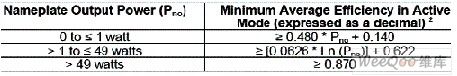
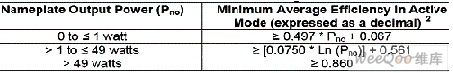
With the development of consumer electronics, energy consumption rate in global electricity of its external power supply(adopter) is dramatically increasing which has been seen as a great energy consumption user.Take America as example, adapters consumes 300 billion degrees electricity per year and it is 11% of the entire country electricity.Today energy conservation and emission reduction is pervasive,at present all governments' regulations are more and more strict to exteral power supply.The United States energy star makes more strict regulations to the average efficiency for external power supply.
Figure 1 shows the power efficency when the output voltage is lagrger than 6V. (View)
View full Circuit Diagram | Comments | Reading(528)
JUNKED_TRANSISTOR_REGULATORS
Published:2009/6/23 4:49:00 Author:Jessie
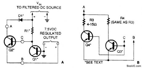
Old transistors can make excellent regulators. Simply use one as a Zener to control the base cur-rent to another transistor (Fig. 68-35A). If the pass transistor cannot supply enough current, you can use two pass transistors in its place (Fig. 68-35B). (View)
View full Circuit Diagram | Comments | Reading(603)
12_Vdc_REGULATED_SUPPLY
Published:2009/6/23 4:48:00 Author:Jessie
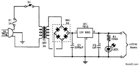
View full Circuit Diagram | Comments | Reading(648)
5_V_LOGlC_REGULATOR_WITH_ELECTRONIC_SHUTDOWN
Published:2009/6/23 4:47:00 Author:Jessie
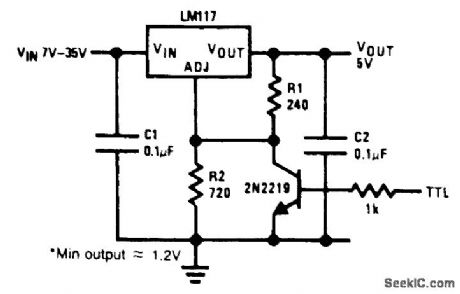
The circuit will shut down to 1.2 V under fault conditions. (View)
View full Circuit Diagram | Comments | Reading(655)
SIMPLE_dc_ac_INVERTER
Published:2009/6/23 4:46:00 Author:Jessie
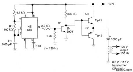
This dc-to-ac inverter is based on the popular 555. A 555 oscillator circuit drives a buffer amplifier consisting of Q1, Q2, and Q3. The circuit operates at 150 to l60 Hz. T1 can be a 6.3-V or l2.6-V ffia-ment transformer as applicable. The frequency canbe changed by changing the values of R1 and/or C1. (View)
View full Circuit Diagram | Comments | Reading(8202)
OP_AMP_AUDIO_MIXER
Published:2009/6/23 4:13:00 Author:May
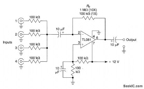
This circuit will mix several audio signals to a common output.RF can be made 1 MΩ for 10 ×(20dB) or 100kΩ for unity gain. (View)
View full Circuit Diagram | Comments | Reading(1302)
FAST_33_V_ADJUSTABLE_REGULATOR
Published:2009/6/23 4:12:00 Author:May
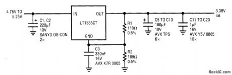
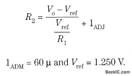
The adjustable version of the LT1585 makes it relatively easy to accommodate multiple microprocessor power-supply voltage specifications. To retain the tight tolerance of the LT1585 internal reference, a 0.5% resistor adjustment is recommended. R1 is sized to carry approximately 10 mA idling current (≤124 Ω), angl R2 is calculated from: (View)
View full Circuit Diagram | Comments | Reading(591)
The Numerical Control DC Regulated Power Supply Circuit 6
Published:2011/7/22 21:55:00 Author:Michel | Keyword: Numerical Control, DC Regulated Power Supply
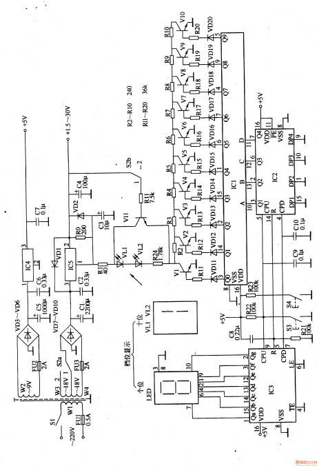
The control DC regulated power supply circuit introduced in the example uses light touch buttons and digital integrated circuit to control the output low voltage of voltage regulation circuit.Its output voltage range is 1.5-30V.The circuit uses 20 reversible gears stepping control(stepping value is 1.5V).The low voltage gear is 1.5-15V(zero to ninth gear) and high voltage gear is 16.5-30V(tenth to ninth gear) and the output votage gear is indicated by LED digital display.
Circuit's Work PrincipleThis control DC regulated power supply circuit is composed of voltage regulation circuit,control circuit and gear indication circuit and it is showed as the picture 5-25.
Voltage regulation circuit consists of mains switch,S1,gear selector switch,S2a ,FU1-FU3,mains transformer,T, rectifier diode ,VD10,capacitor,C1-C7,voltage regulator IC,IC4 and resistor,RO. (View)
View full Circuit Diagram | Comments | Reading(925)
BUFFERED_REFERENCE_SUPPLY
Published:2009/6/23 4:45:00 Author:Jessie

This buffered reference (for 1.23 V or ntore) uses a supply voltage of greater than 3 V. (View)
View full Circuit Diagram | Comments | Reading(505)
dc_dc_CONVERTER
Published:2009/6/23 4:45:00 Author:Jessie
This low-power converter will supply about 100 mW of dc to a load and it is useful to isolate or derive dc voltages. It operates at around 200 kHz. L1 is wound on a 22-mm diameter x 13-mm high pot core with #32 magnet wire. The primary is 80 turns and the secondary is 80 turns (for 12-V nom-inal output). The two windings should be insulated for the expected voltage difference between in-put and output in insulation applications. (View)
View full Circuit Diagram | Comments | Reading(1)
| Pages:173/291 At 20161162163164165166167168169170171172173174175176177178179180Under 20 |
Circuit Categories
power supply circuit
Amplifier Circuit
Basic Circuit
LED and Light Circuit
Sensor Circuit
Signal Processing
Electrical Equipment Circuit
Control Circuit
Remote Control Circuit
A/D-D/A Converter Circuit
Audio Circuit
Measuring and Test Circuit
Communication Circuit
Computer-Related Circuit
555 Circuit
Automotive Circuit
Repairing Circuit