
Index 171
COLD_CATHODE_FLUORESCENT_LAMP_POWER_SUPPLY
Published:2009/6/25 1:54:00 Author:Jessie
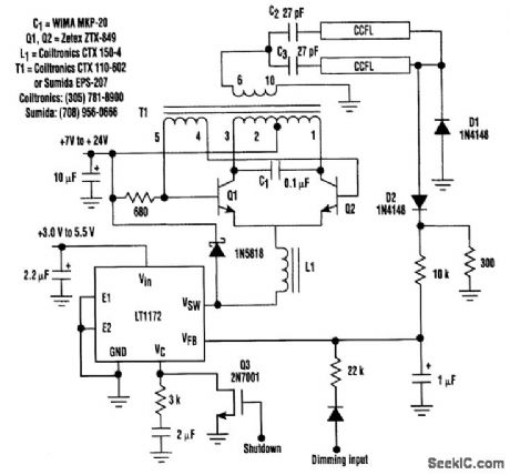
This circuit is a 92%-efficient power supply for cold-cathode fluorescent lamps (CCFLs), which are used to backlight LCD in portable equipment. The efficiency depends heavily on the component types, particularly C1, Q1, Q2, L1, and T1, whose manufacturers are noted. (View)
View full Circuit Diagram | Comments | Reading(1683)
HIGH_VOLTAGE_SUPPLY
Published:2009/6/25 1:50:00 Author:May
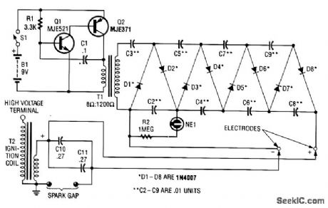
This circuit uses a transistor oscillator and a voltage multiplier to charge C10 and C11 to a high voltage. When the spark gap breaks down, T2 produces a high-voltage pulse via the capacitance discharge of C10 and C11 into its primary. T2 is an auto ignition coil. (View)
View full Circuit Diagram | Comments | Reading(3304)
SINGLE_CHIP_dc_SUPPLY_FOR_120_TO_240_Vac_OPERATION
Published:2009/6/25 1:48:00 Author:May
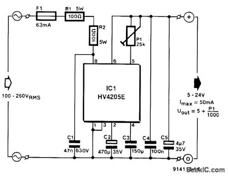
Direct derivation of 5 to 24 Vdc from ac mains, without a transformer is possible with this cir-cuit. Note that a direct mains connection to the dc output exists. Suitctble safety precautions must be taken. (View)
View full Circuit Diagram | Comments | Reading(979)
PHOTOMULTIPLIER_CIRCUIT
Published:2009/6/25 1:46:00 Author:May
This circuit is typical of the way that a photomultiplier tube is used. The circuit shown is ac coupled,but if dc coupling is needed,the capacitor can be omitted and a suitable interfacing method used,A typical tube is the widely available 931/931A. (View)
View full Circuit Diagram | Comments | Reading(1333)
NEGATIVE_VOLTAGE_SUPPLY
Published:2009/6/25 1:43:00 Author:May
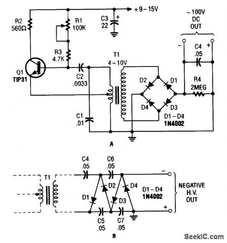
The combination Hartley oscillator/step-up transformer shown in A can generate significant negative high voltage, especially if the voltage output of the transformer is multiplied by the circuit. (View)
View full Circuit Diagram | Comments | Reading(847)
HIGH_POWER_CONTROLFOR_SENSITIVE_CONTACTS
Published:2009/6/25 1:40:00 Author:May
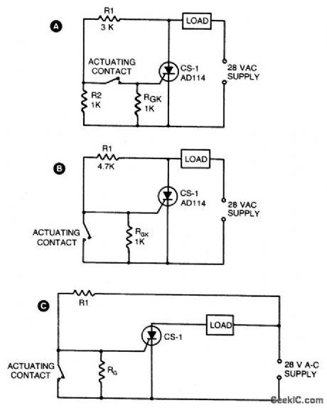
Two simple arrangements for resistive loads are shown in A & B. The circuit in A will provide load power when the actuating contact is closed, and no power when the contact is open. B provides the reierse of this action-power being supplied to the load when the contact is open with no load power when the contact is closed. If desired, both circuits can be made to latch by operating with dc instead of the indicated ac supply. In both of these circuits, voltage across the sensitive contacts is under 5 volts, and contact current is below 5 mA. For inductive loads, R1 would normally be returned to the opposite side of the load as shown in C. (View)
View full Circuit Diagram | Comments | Reading(1169)
PHOTOMULTIPLIER_SUPPLY
Published:2009/6/25 0:03:00 Author:Jessie
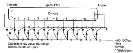
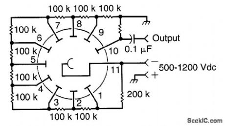
A Cockcroft-Walton voltage multiplier supplies the stepped voltage required for the dynodes of the PMT without the power-wasting voltage-divider resistor string that is traditionally used. (View)
View full Circuit Diagram | Comments | Reading(1449)
FLUORESCENT_TUBE_POWER_SUPPLY
Published:2009/6/25 0:02:00 Author:Jessie
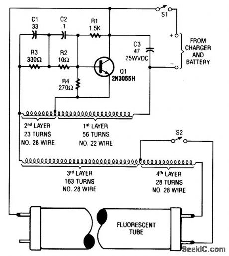
A 2N3055 oscillator (Q1) drives a homemade transformer, wound on a 5/16 × l7/8 ferrite rod. S2 is used as a filament switch and it can be eliminated, if desired. A 20-W fluorescent tube is recom-rnended. The supply is 12 V. (View)
View full Circuit Diagram | Comments | Reading(756)
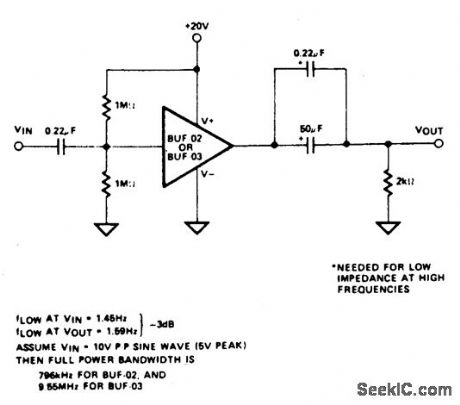
SINGLE_SUPPLY_AC_BUFFER_HIGH_SPEED
Published:2009/6/24 22:44:00 Author:May
View full Circuit Diagram | Comments | Reading(574)
LOW_BATTERY_INDICATOR
Published:2009/6/24 22:31:00 Author:May
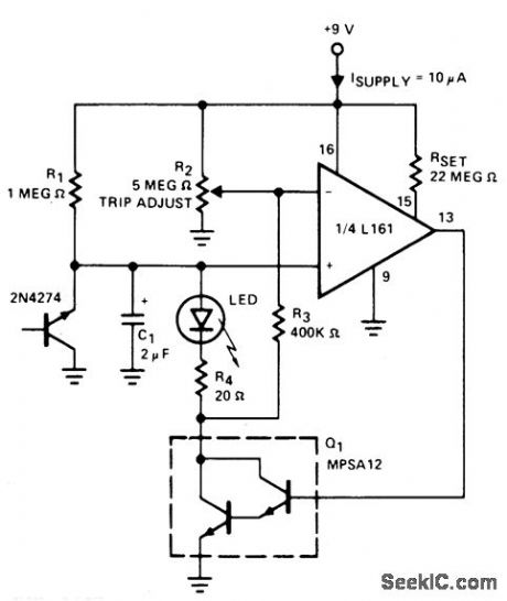
The indicator flashes an LED when the battery voltage drops below a certain threshold. 2N4274 emitter-base junction serves as a zener which establishes about 6V on the L161's positive input. As the battery drops, the L161 output goes high. This turns on the Darlington, which discharges C1 through the LED. The interval between flashes is roughly two seconds and gives a low battery warning with only 10 μA average power drain. (View)
View full Circuit Diagram | Comments | Reading(3502)
SIGNAL_SOURCE_FOR_AUDIO_AMPLIFIER_INVERTER
Published:2009/6/24 22:28:00 Author:May
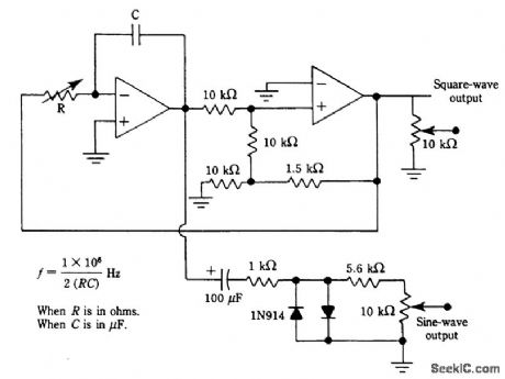
Two op amps (741, etc..) are used in this oscillator circuit. A square wave is available and a sine wave, obtained by shaping the triangle waveform, is also provided. (View)
View full Circuit Diagram | Comments | Reading(978)
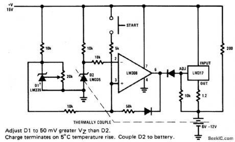
FAST_CHARGER_FOR_NI_CAD_BATTERIES
Published:2009/6/24 22:22:00 Author:May
View full Circuit Diagram | Comments | Reading(715)
LOW_COST_TRICKLE_CHARGER_FOR_12_V_STORAGE_BATTERY
Published:2009/6/24 22:21:00 Author:May
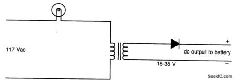
Circuit Charge rate can be varied and is based on the size of bulb. (View)
View full Circuit Diagram | Comments | Reading(509)
BATTERY_CHARGING_REGULATOR
Published:2009/6/24 22:20:00 Author:May
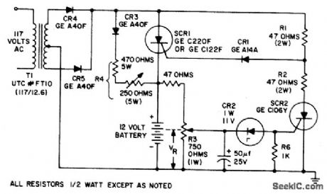
The circuit is capable of charging a 12 volt battery at up to a six ampere rate. Other volt-ages andcurrents, from6 to600volts and upto 300 amperes, can be accommodated by suitable component selection. When the battery voltage reaches its fully charged level, the charging SCR shuts off, and a trickle charge as deter-mined by the value of R4 continues to flow. (View)
View full Circuit Diagram | Comments | Reading(2088)
SIMPLE_NI_CAD_BATTERY_ZAPPER
Published:2009/6/24 22:19:00 Author:May
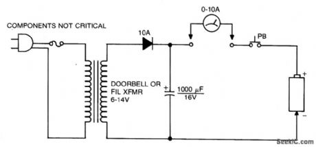
This circuit is used to clear internal shorts in nickel cadmium batteries. To operate, connect ni-cad to output and press the pushbutton for three seconds. (View)
View full Circuit Diagram | Comments | Reading(818)
CONSTANT_VOLTAGE,CURRENT_LIMITED_CHARGER
Published:2009/6/24 22:17:00 Author:May
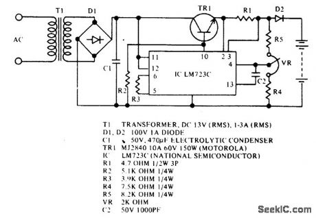
For 12 V sealed lead-acid batteries. (View)
View full Circuit Diagram | Comments | Reading(979)
AUTOMOTIVE_CHARGER_FOR_NI_CAD_BATTERY_PACKS
Published:2009/6/24 22:16:00 Author:May
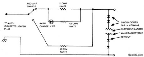
The number of silicon diodes across the output is determined by the voltage of the battery pack. Figure each diode at 0.7 volt. For example, a 10.9- volt pack would require 10.9/0.7 = 15.57, or 16 diodes. (View)
View full Circuit Diagram | Comments | Reading(632)
NI_CAD_CHARGER_WITH_CURRENT_AND_VOLTAGE_LIMITING
Published:2009/6/24 22:14:00 Author:May
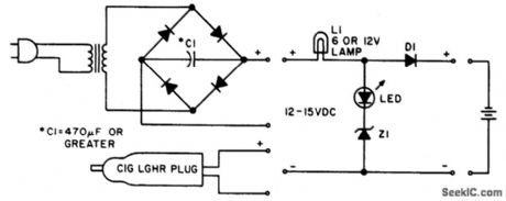
Lamp L1 will glow brightly and the LED will be out when the battery is low and being charged, but the LED will be bright and the light bulb dim when the battery is almost ready. L1 should be a light bulb rated for the current you want (usually the battery capacity divided by 10).Diode Dl should be at least 1 A,and Z1is a 1 W zerLer diode with a voltage determinedby the full-charge battery voltage Π11nUS 1,5 V。After the battery IS fully charged, the circuit、vill float it at about battery capacity divided by100 mA. (View)
View full Circuit Diagram | Comments | Reading(642)
200_mA_HOUR,12_V_NI_CAD_BATTERY_CHARGER
Published:2009/6/24 22:13:00 Author:May
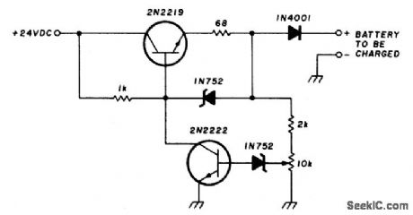
This circuit charges the battery at 75 mA until the battery is charged, then it reduces the current to a trickle rate. It will completely recharge a dead battery in four hours and the battery can be left in the charger indefinitely. To set the shut-off point, connect a 270-ohm, 2-watt resistor across the charge terminals and adjust the pot for 15.5 volts across the resistor. (View)
View full Circuit Diagram | Comments | Reading(1295)
AUTOMATIC_SHUTOFF_BATTERY_CHARGER
Published:2009/6/24 22:11:00 Author:May
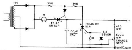
Adjust by setting the 500 ohm resistor while attached to a fully charged battery. (View)
View full Circuit Diagram | Comments | Reading(1296)
| Pages:171/291 At 20161162163164165166167168169170171172173174175176177178179180Under 20 |
Circuit Categories
power supply circuit
Amplifier Circuit
Basic Circuit
LED and Light Circuit
Sensor Circuit
Signal Processing
Electrical Equipment Circuit
Control Circuit
Remote Control Circuit
A/D-D/A Converter Circuit
Audio Circuit
Measuring and Test Circuit
Communication Circuit
Computer-Related Circuit
555 Circuit
Automotive Circuit
Repairing Circuit