
Index 162
Low_power_33_V_to_5_V_supply
Published:2009/7/24 23:01:00 Author:Jessie
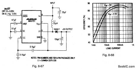
Figure 8-67 shows a MAX731 connected to provide 5 V from a 3.3-V supply. Figure 8-68 shows the efficiency curves. This PWM boost regulator is designed for low-noise, battery-powered applications, such as cellular phones or sub-notebook computers without rotating disk drives (where the maximum +5-V load is 2 W or less). The input voltage range is 1.4 V to 5 V, with a quiescent current of 2 mA, and a maximum load current of 350 mA. The no-load start-up voltage is 1.8 V. The switching frequency is 170 kHz, and the shutdown current is 35 pt,A. MAXIM BATTERY MANAGEMENT CIRCUIT COLLECTION, 1994, P. 41. (View)
View full Circuit Diagram | Comments | Reading(618)
Automatic switching circuit of Multimeter AC to DC
Published:2011/7/17 23:12:00 Author:Sophia | Keyword: Automatic switching, Multimeter AC to DC
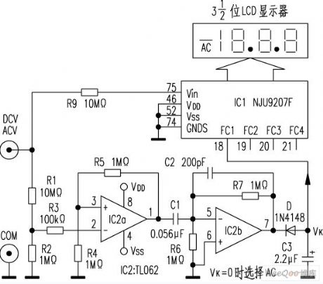
The AC and DC measurement conversion of ordinary digital multimeter is completed by manual operation. New digital multimeter DT860D adopts Automatic range switching chip NJU9207F, and is equiped with external auxiliary circuit to achieve AC - DC (AC / DC) automatic conversion measurements.
AC / DC automatic conversion circuit is shown below.
(View)
View full Circuit Diagram | Comments | Reading(2676)
High power adjustable regulated power supply using TL431
Published:2011/8/1 2:44:00 Author:Ecco | Keyword: High power , adjustable , regulated power supply
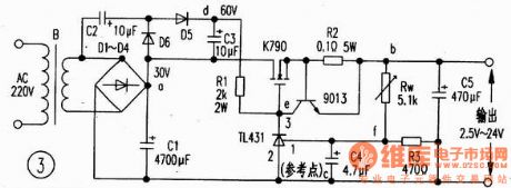
Precision voltage reference ICTL431 is T0-92 packaged, it is shown in Figure 1. Its performance is continuously adjustable output voltage being up to 36V, wide operating current range is 0.1. 100mA, the typical dynamic resistor is 0.22Ω, the output clutter is low. Figure 2 is a typical application of TL431, of which both ends of the output voltage of ③, ② feet V is 2.5 (R2 ten R3) V/R3. If you change the size of the resistance of R2, you can change the output voltage. Figure 3 uses it as external voltage reference and to drive the regulator FET K790, which makes output currentbe about 6A, the circuit is simple with safe power supply.The working principle
As Figure 3 shown, 220v voltage is stepped-down by the transformer B, rectified by D1-D4, filtered by C1. In addition, D5, D6, C2, C3 form double voltage circuit(making Vdc = 60V), Rw, R3 form voltage divider, T1431, R1 form sampling amplifier, 9013, R2 form limiting protection circuit, K790 FET tube is adjusting tube (which can be directly used in parallel), and C5 is the output filter circuit.
(View)
View full Circuit Diagram | Comments | Reading(4596)
Power_op_amp_with_remote_sensing
Published:2009/7/24 23:45:00 Author:Jessie
This circuit shows an LM12 (Fig. 10-46) connected as a differential-input amplifier with dc feedback from a remotely sensed load. The ac feedback is directly from the op-amp output and the signal common at the sending end. There is no feedback from the load at high frequencies. The optimum capacitance for C1/C2 depends on the cable delay. Note that the common and LM12 output cables must be capable of carrying a typical 10A, whereas the feedback-sensing cables can be small. For a single-ended input, strap the unused input terminal to common. (View)
View full Circuit Diagram | Comments | Reading(850)
Power_op_amp_voltage_regulator_with_overvoltage_protection
Published:2009/7/24 23:44:00 Author:Jessie
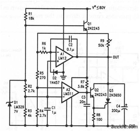
This circuit shows an LM12 (Fig, 10-46) connected with other components to form a positive regulator. The output is 4-70V, set by R9. Should the LM12 not be able to control an overvoltage condition, the SCR Q3 will crowbar the output. (View)
View full Circuit Diagram | Comments | Reading(699)
Power_op_amp_voltage_current_converter
Published:2009/7/24 23:25:00 Author:Jessie

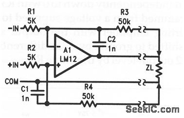
As shown by the equation, this LM12 (Fig. 10-46) circuit provides an output current proportional to input voltage. This circuit requires precise resistor matching, and/or trimming by R3, to get high output resistance. Any inductance in R6 will reduce bandwidth. (View)
View full Circuit Diagram | Comments | Reading(844)
Power_op_amp_master_slave
Published:2009/7/24 23:24:00 Author:Jessie
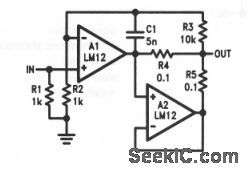
This circuit shows two LM12s (Fig. 10-46) connected in a master/slave configuration to increase the load current capability. Notice that a separate control amplifier (such as used in Fig. 10-47) is not required. However, the high-frequency performance of the master/slave configuration is not as good as with the Fig. 10-47 circuit. (View)
View full Circuit Diagram | Comments | Reading(685)
4__to_20_mA_current_loop_transmitter
Published:2009/7/24 23:30:00 Author:Jessie
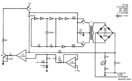
This circuit transmits an industry standard 4-20 mA current loop signal to valves and other actuators. The 5-V circuit uses a servo-controlled dc/dc converter to generate the compliance voltage necessary for loop-current requirements (the circuit will drive 4 to 20 mA into loads as high as 2.2 kΩ, or 44-V compliance, and is inherently short-circuit protected). To calibrate, short the output, apply 0 V to the input, and adjust the 4-mA trim for 0.3996 V across the 100-Ω resistor. Next, increase the input to 4.000V and trim the 20-mA adjustment for 1.998 V across the 100-Ωresistor. Repeat this procedure until both points are fixed. The gain-trim network shunting the 100-Ω resistor requires the odd voltage-trim target values (1.998 and 0.3996). However, the output current swings between 4.000 and 20.00 mA, when the input voltage is varied between 0 V and 4V. (View)
View full Circuit Diagram | Comments | Reading(1900)
RS_232_power_supply
Published:2009/7/25 3:10:00 Author:Jessie
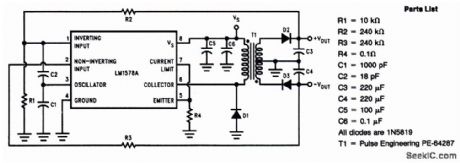
This circuit operates with inputs as low as 4.2 V, and delivers an output of±12 V at ±40 mA with an efficiency of better than 70%. Load regulation is ±1.25% (from 10% to 100% of full load) and line regulation is ±0.08%, with less than 40-mV pp ripple. (View)
View full Circuit Diagram | Comments | Reading(783)
Step_up__30_V_to_100_V_at_100_mA_flyback_converter
Published:2009/7/25 1:42:00 Author:Jessie
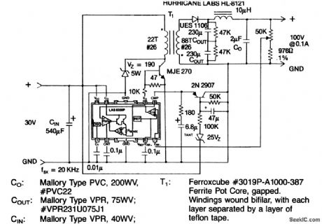
This circuit converts 30-V to 100-V(adjustable)output. (View)
View full Circuit Diagram | Comments | Reading(754)
Step_up_step_down_6__to_22__to_12_Vdc_converter
Published:2009/7/25 1:41:00 Author:Jessie

This circuit converts 6 V to 22 V (through operation of a switching regulator) and then reduces the 22 V to a fixed 12 V (through operation of an LAS1612 linear regulator). (View)
View full Circuit Diagram | Comments | Reading(627)
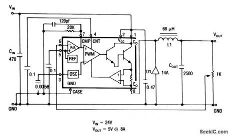
5_V_step_down_converter
Published:2009/7/25 1:27:00 Author:Jessie
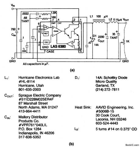
This circuit provides 5-V output(adjustable)at 8A.Figure 4-21B shows component source information. (View)
View full Circuit Diagram | Comments | Reading(615)
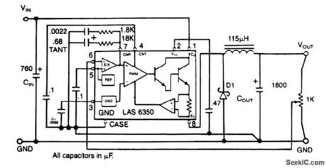
5_V_step_down_converter_with_adjustable_current_limit
Published:2009/7/25 1:25:00 Author:Jessie
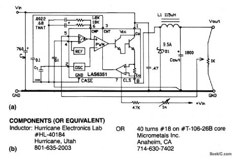
This circuit has an adjustable Vout, with an adjustable current limit,Figure 4-20B shows component source information. (View)
View full Circuit Diagram | Comments | Reading(822)
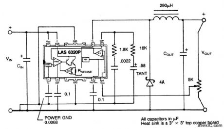
5_V_adjustable_step_down_converter_with_a_fixed_current_limit_
Published:2009/7/25 1:24:00 Author:Jessie
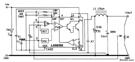
This circuit has an adjustable Vout, with a fixed current limit of 5A. (View)
View full Circuit Diagram | Comments | Reading(610)
Adjustable_dc_dc_step_down_converter_2A
Published:2009/7/25 1:23:00 Author:Jessie
This circuit is similar to that of Fig.4-7,except that this circuit can be operated with inputs of 15 to 25 V. (View)
View full Circuit Diagram | Comments | Reading(758)
Adjustable_dc_dc_step_down_converter5A
Published:2009/7/25 1:22:00 Author:Jessie
This circuit is similar to that of Fig.4-11,except that this circuit can be operated with inputs of 17.7 to 22.3V. (View)
View full Circuit Diagram | Comments | Reading(700)
dc_dc_step_down_converters
Published:2009/7/25 1:21:00 Author:Jessie
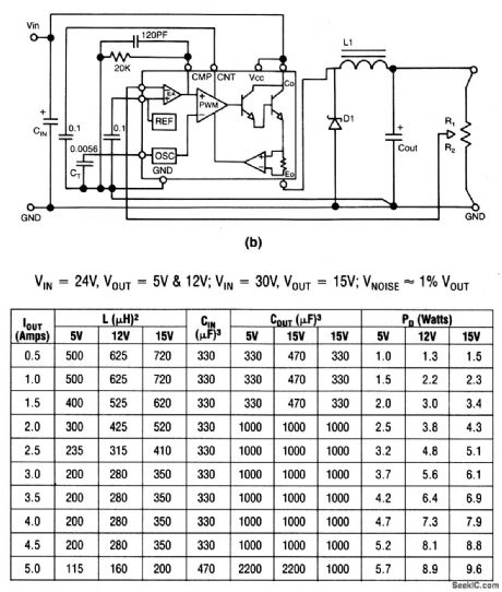
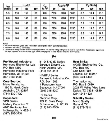
This circuit shows a dc/dc converter with adjustable output.Figure4-16B shows the values of Cin,Cout、andL required for Various input and output voltages,The part numbers required for various output-current limits are given in Figs.4-7 through 4-14,For example, use LAS-6320/6420 for currents up to 2 A、LAS-6330/6430 for currents up to 3 A,LAS-6350/6450 for currents up to 5 A、and LAS-6380/6480 for currents up to 8 A. Figure 4-16C shows information on component sources. (View)
View full Circuit Diagram | Comments | Reading(800)
dc_dc_step_down_microconverters
Published:2009/7/25 1:19:00 Author:Jessie
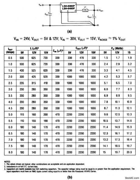
The LSH components require only two capacitors and a choke to form a dc/dc step-down converter. Figure 4-15B shows the values of Cin, Cout, and L required for various input and output voltages. The part numbers required for various output-current limits are given in Figs. 4-3 through 4-6. For example, use LSH-6325 for currents up to 2A, LSH-6335/6435 for currents up to 3 A, LSH-6355/ 6455 for currents up to 5 A, and LSH-6389/6489 for currents up to 8 A. Figure 4-16C shows information on component sources. (View)
View full Circuit Diagram | Comments | Reading(741)
Adjustable_dc_dc_step_up_converter_25_A
Published:2009/7/25 1:17:00 Author:Jessie

This circuit shows an LAS-6380/6480 used as a step-up converter with an adjustable output. (View)
View full Circuit Diagram | Comments | Reading(771)
Adjustable_dc_dc_step_down_converter8_A
Published:2009/7/25 1:16:00 Author:Jessie
This circuit shows an LAS-6380/6480 used as a step-down converter with an adjustable output. (View)
View full Circuit Diagram | Comments | Reading(798)
| Pages:162/291 At 20161162163164165166167168169170171172173174175176177178179180Under 20 |
Circuit Categories
power supply circuit
Amplifier Circuit
Basic Circuit
LED and Light Circuit
Sensor Circuit
Signal Processing
Electrical Equipment Circuit
Control Circuit
Remote Control Circuit
A/D-D/A Converter Circuit
Audio Circuit
Measuring and Test Circuit
Communication Circuit
Computer-Related Circuit
555 Circuit
Automotive Circuit
Repairing Circuit