
Index 166
Extending_three_terminal_regulator_current_capability_with_shutdown
Published:2009/7/25 2:20:00 Author:Jessie
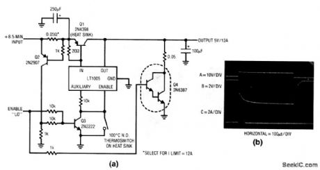
This circuit extends the 1-A capacity of an LT1005 multifunction regulator to 12 A, while retaining the enable feature and auxiliary 5-V output. Q2 senses the current-dependent voltage across the 0.05-Ω shunt (the shunt value can be selected for the desired current limit). When the shunt voltage reaches the desired shutoff point, Q2 turns on, biases Q3, and shuts down the regulator through the enable pin. The 100℃ thermoswitch limits dissipation in Q1 during prolonged short-circuit conditions by disabling the LT1005, and it should be mounted on the Q1 heatsink. Q4 can be omitted if fast turn-off is not needed. When the enable command is given (trace A, Fig. 9-8B) Q3 turns on, cuts off the LT1005, and forces Q1 off. Simultaneously, Q4 (if used) turns on and pulls down the regulator output (trace B). This sinks the 100-μF capacitor discharge current (trace C). (View)
View full Circuit Diagram | Comments | Reading(651)
Converter_with_wide_input_range
Published:2009/7/25 2:19:00 Author:Jessie
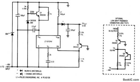
This circuit provides 5-V output at 0.5 A, for inputs from -40 V to -60 V. Q2 introduces a -2 mV/℃ drift. This drift can be compensated by the circuit shown in dashed lines,Jthough line regulation is somewhat degraded. (View)
View full Circuit Diagram | Comments | Reading(757)
High_efficiency_converter_with_nonisolated_output
Published:2009/7/25 2:17:00 Author:Jessie
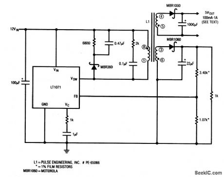
This circuit is a nonisolated version of the circuit in Fig. 4-46. (View)
View full Circuit Diagram | Comments | Reading(719)
High_efficiency_converter_with_floating_output
Published:2009/7/25 2:16:00 Author:Jessie
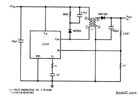
This circuit provides 5-V output at 1 A for a 12-V input.Regulation stays within ±100 mV from 100% to 100% of output rating, with excursion exceeding 900 mV at no load.Notice that the outputis fully isolated. (View)
View full Circuit Diagram | Comments | Reading(741)
High_efficiency_buck_converter
Published:2009/7/25 2:14:00 Author:Jessie
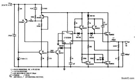
This circuit provides 5-V output at 5 A from a 9.5- to 14.5-V input, with about 90% efficiency. (View)
View full Circuit Diagram | Comments | Reading(833)
The high speed switch power controller M62213FP switch regulated power supply circuit
Published:2011/7/24 4:05:00 Author:Seven | Keyword: high speed, controller, power supply
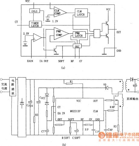
In Figure (b) is a switch regulated power supply composed of high speed switch power controller M62213FP. The conducting time of the power supply output pulse is decided by the SOFT resistor, if a capacitor is parallel with the resistor, the starting time will be prolonged, so the soft start can be fulfilled. When M62213FP is starting, the working voltage of it is provided by R1 after the AC power supply voltage is rectified.
Figure1 the internal structure of M62213FP
(View)
View full Circuit Diagram | Comments | Reading(569)
The radar energy-saving lamp base circuit
Published:2011/7/21 3:13:00 Author:Seven | Keyword: energy-saving lamp
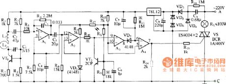
The radar energy-saving lamp base is actually a human body microwave sensor switch. When people come into the effective range, the light will glow on its own and put out after the delayed time. If the people are in the range all the time, the lamp is going to glow. The radar energy-saving lamp is equipped with the light control function, which makes the lamp only work at night. In the figure is the radar energy-saving lamp base circuit.
(View)
View full Circuit Diagram | Comments | Reading(739)
SIMPLE_CROWBAR
Published:2009/6/28 22:31:00 Author:May
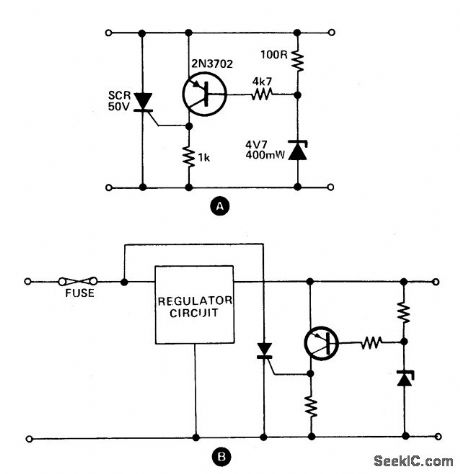
These circuits provide o,vervoltage protection in case of voltage regulator failure or application of an external voltage. Intended to be used with a supply offering some form of short circuit protection, either foldback, current limiting, or a simple fuse. The most likely application is a 5 V logic supply, since TTL is easily damaged by excess voltage. The values chosen in A are for a 5 V supply, although any supply up to about 25 V can be protected by simply choosing the appropriate zener diode. When the supply voltage exceeds the zener voltage +0.7 V, the transistor turns on and fires the thyristor. This shorts out the supply, and prevents the voltage rising any further. In the case of a supply with only fuse protection, it is better to connect the thyristor the regulator circuit when the crowbar operates. The thyristor should have a current rating about twice the expected short circuit current and a maximum voltage greater than the supply voltage. The circuit can be reset by either switching off the supply, or by breaking the thyristor circuit with a switch. (View)
View full Circuit Diagram | Comments | Reading(3384)
BATTERY_MONITOR
Published:2009/6/28 22:27:00 Author:May
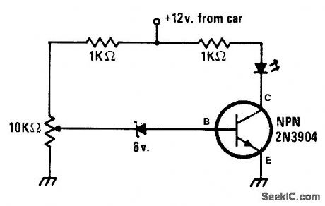
Basic circuit energizes LED when battery voltage drops to level set by 10K pot. Any number of additional circuits can be added, for reading battery voltage in 1-V steps oreven steps assmall as 0.1 V. Circuitsup-plements idiot light that replaces ammeter in most modern cars. LED type is not criticaL-J. Sandier, 9 Pro jects under $9, Modem Electron-ics, Sept, 1978, p 35-39. (View)
View full Circuit Diagram | Comments | Reading(2293)
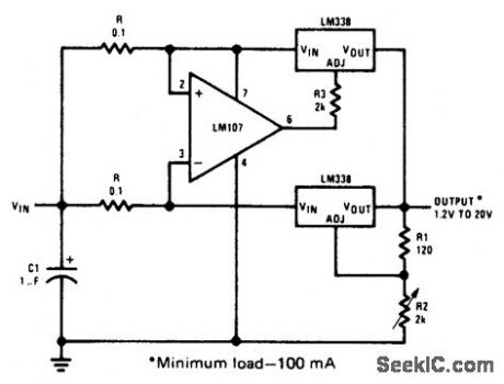
60_A_VARIABLE_OUTPUT_SWITCHING_REGULATOR
Published:2009/6/28 22:26:00 Author:May
View full Circuit Diagram | Comments | Reading(799)
MULTIPLE_OUTPUT_SWITCHING_REGULATOR_FOR_USE_WITH_MPUs
Published:2009/6/28 22:25:00 Author:May
View full Circuit Diagram | Comments | Reading(673)
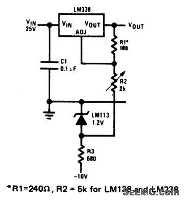
1ADJUSTABLE_OUTPUT_REGULATOR
Published:2009/6/28 22:23:00 Author:May
View full Circuit Diagram | Comments | Reading(581)
SIMPLE_SPLIT_POWER_SUPPLY
Published:2009/6/28 22:22:00 Author:May
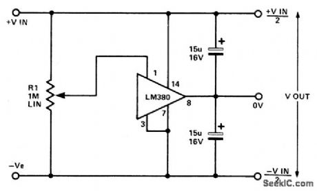
This circuit utilizes the quasicomplementary output stage ofthe popular LM380 audio power IC. The device is internally biased so that with no input the output is held midway between the supply rails. R1, which should be initially set to mid-travel, is used to nullify any inbalance in the output.Regulation of Vout depends upon the circuit feeding the LM380, but positive and negative outputs will track accurately irrespective of input regulation and unbalanced loads. The free-air dissipation is a little over 1 watt, and so extra cooling may be required. The device is fully protected and will go into thermal shutdown if its rated dissipation is exceeded. Current limiting occurs if the output current exceeds 1.3 A. The input voltage should not exceed 20 V. (View)
View full Circuit Diagram | Comments | Reading(791)
LOW_VOLTAGE_REGULATOR(VSUBout_SUB=2_TO_7_V)
Published:2009/6/28 22:21:00 Author:May
View full Circuit Diagram | Comments | Reading(590)
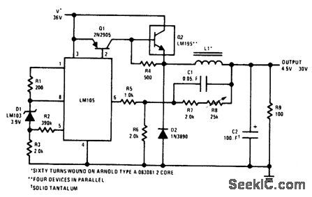
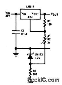
HIGH_VOLTAGE_REGULATOR(VSUBout_SUB=_7_V_TO_37_V)
Published:2009/6/28 22:19:00 Author:May
View full Circuit Diagram | Comments | Reading(504)
ADJUSTABLE_REGULATOR_O_10_V_AT_3_A
Published:2009/6/28 22:18:00 Author:May
View full Circuit Diagram | Comments | Reading(598)
10_A_REGULATOR
Published:2009/6/28 22:17:00 Author:May
View full Circuit Diagram | Comments | Reading(648)
0_TO_22_V_REGULATOR_
Published:2009/6/28 22:17:00 Author:May
View full Circuit Diagram | Comments | Reading(634)
0_TO_30_V_REGULATOR
Published:2009/6/28 22:16:00 Author:May
View full Circuit Diagram | Comments | Reading(587)
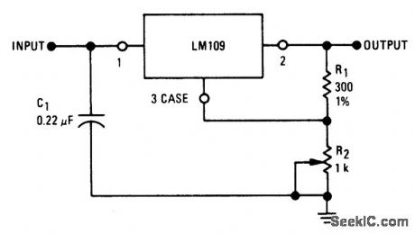
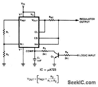
REMOTE_SHUTDOWN_REGULATOR_WITH_CURRENT_LIMITING
Published:2009/6/28 22:16:00 Author:May
View full Circuit Diagram | Comments | Reading(631)
| Pages:166/291 At 20161162163164165166167168169170171172173174175176177178179180Under 20 |
Circuit Categories
power supply circuit
Amplifier Circuit
Basic Circuit
LED and Light Circuit
Sensor Circuit
Signal Processing
Electrical Equipment Circuit
Control Circuit
Remote Control Circuit
A/D-D/A Converter Circuit
Audio Circuit
Measuring and Test Circuit
Communication Circuit
Computer-Related Circuit
555 Circuit
Automotive Circuit
Repairing Circuit