
Circuit Diagram
Index 1048
ST24C04 I2C bus data storage IC diagram
Published:2011/5/9 21:40:00 Author:Rebekka | Keyword: bus data storage IC
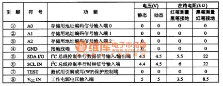
ST24C04 and I2C are bus data memory integrated circuits. It is widely used for video, audio, air conditioning and other appliances remote control system. It is compatible with single-chip microcomputer to finish the storage and recall functions of program.The pre-stored program of ST24C04 IC changes with different application occasions. So pay attention to the chage of memorizer.ST7C04 integrated circuit uses 8-pin dual in-line package, the pin functions and data of the integrated circuit are listed in Table 1.
(View)
View full Circuit Diagram | Comments | Reading(567)
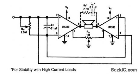
Minimum_component_bridge_amplifier_with_voltage_divider_input
Published:2009/7/23 20:18:00 Author:Jessie
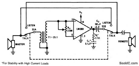
This circuit shows a bridge-amplifier configuration with a voltage-divider input (rather than the common-mode input of Fig. 1-37). With the circuit of Fig. 1-39, if the source voltage Vs (pin 14) is more than 3 inches from the power-source filter capacitor, pin 14 should be decoupled with a 1-μF tantalum capacitor. (View)
View full Circuit Diagram | Comments | Reading(1553)
High_impedance_low_capacitance_video_amplifier
Published:2009/7/23 20:17:00 Author:Jessie
This compound series-feedback circuit provides high input impedance and stable, wideband gain for general-purpose video-amplifier applications. (View)
View full Circuit Diagram | Comments | Reading(696)
Precision_current_source
Published:2009/7/23 20:17:00 Author:Jessie
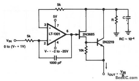
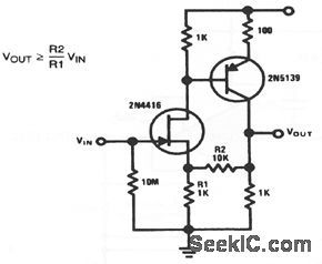
As shown, the output current of this circuit depends on VIN and the value of R. Notice that VIN can be anything from 0 to (V- + 1 V), and V- can be -2 to -35 V. (View)
View full Circuit Diagram | Comments | Reading(0)
High_impedance_low_capacitance_video_buffer
Published:2009/7/23 20:16:00 Author:Jessie
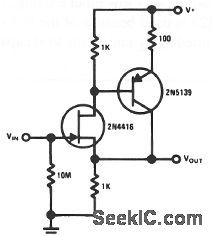
This compound series-feedback circuit provides high input impedance and stable, wideband unity gain for general-purpose video-buffer applications. (View)
View full Circuit Diagram | Comments | Reading(738)
Voltage_controlled_variable_gain_video_amplifier
Published:2009/7/23 20:15:00 Author:Jessie
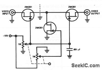
The 2N4391 provides a low RDS(ON) (less than 30Ω). The tee attenuator provides for optimum dynamic linear range for attenuation. If complete turnoff is desired, attenuation of greater than 100 dB can be obtained at 10 MHz, provided that proper RF-construction techniques are used (proper shielding to prevent input passing to output around the FETs). (View)
View full Circuit Diagram | Comments | Reading(1443)
Photodiode_amplifier
Published:2009/7/23 20:14:00 Author:Jessie
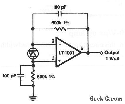
This circuit produces a 1-Voutput for a 1-μA input. (View)
View full Circuit Diagram | Comments | Reading(0)
FET_cascode_video_amplifier
Published:2009/7/23 20:14:00 Author:Jessie
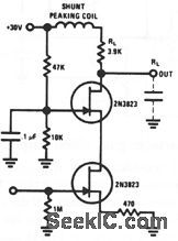
This circuit features very low input loading, and reduction of feedback to almost zero. The 2N3823 is used because of the low capacitance and high Yfs. Amplifier bandwidth is limited by RL and by the load capacitance.
(View)
View full Circuit Diagram | Comments | Reading(0)
Minimum_component_bridge_amplifier_with_quiescent_balance_control
Published:2009/7/23 20:14:00 Author:Jessie
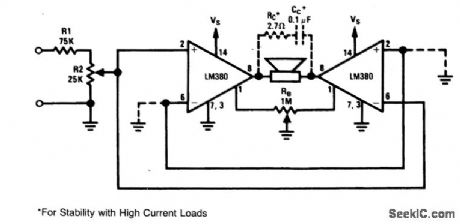
The quiescent output voltage of the LM380 is specified at 9 ±1V with an 18-V supply. Therefore, under worst-case conditions, it is possible for the circuit of Fig. 1-37 to have 2-V across the load. With an 8-Ω speaker, this 0.25 A of direct current might be excessive. Three alternatives are available:1) take care to match the quiescent voltages, 2) use a non-polar capacitor in series with the load (speaker), 3) use the offset balance control (Fig. 1-38). (View)
View full Circuit Diagram | Comments | Reading(873)
Wideband_AGC_amplifier
Published:2009/7/23 20:13:00 Author:Jessie
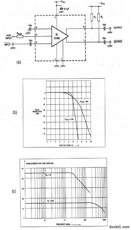
This circuit shows an SL6140 as a high-gain video amplifier, with AGC capable of reducing gain by over 70 dB (Fig. 3-20B). Single-ended voltage gain and bandwidth are set by values of RL (3-20C). (View)
View full Circuit Diagram | Comments | Reading(0)
Microvolt_comparator_with_TTL_output
Published:2009/7/23 20:12:00 Author:Jessie
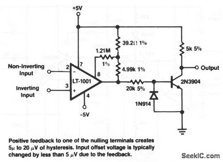
This circuit produces a full 5-V TTL output with microvolt (differential )inputs. (View)
View full Circuit Diagram | Comments | Reading(753)
PRACTICAL_CURRENT-LIMITING_COIL_DRIVER
Published:2009/7/6 3:54:00 Author:May
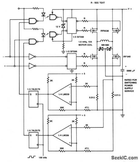
The p-channel devices are switched off by current sensors when the coil current reaches 10 A. The operation is similar to that of a switching-type power supply. The Schottky diodes and resistors are for spike protection. (View)
View full Circuit Diagram | Comments | Reading(587)
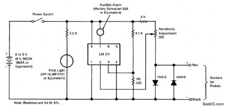
ADJUSTABLE,AUDIBLE_CONTINUITY_TESTER_FOR_DELICATE_CIRCUITS
Published:2009/7/6 3:54:00 Author:May
Circuit Notes
The tester gives an audible indication, making it unnecessary for the user to look directly at the instrument to observe a meter reading. In addition, the current and voltage of the tester are strictly limited. It can apply no more than 0.6 volts dc and no more than 3 mA through the probes. It can therefore be used safely on circuit boards in which semiconductor components have been installed, and on complementary metal oxide/semiconductor integrated circuits, which are highly susceptible to damage during testing. The tester can be adjusted to indicate continuity below any resistance value up to 35 ohms. For example, if the user sets the tester to 30 ohms, the unit will emit an audible tone whenever the resistance between the probes is 30 ohms or less; if, for example, the resistance is 30.2 ohms, the unit will remain silent. (View)
View full Circuit Diagram | Comments | Reading(1308)
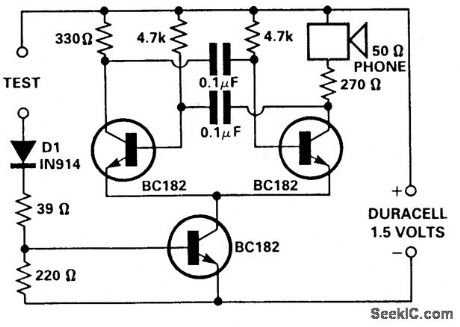
SIMPLE_CONTINUITY_TESTER
Published:2009/7/6 3:51:00 Author:May

Circuit Notes
The pitch of the tone is dependent upon the resistance under test. The tester will respond to resistance of hundreds of kilohms, yet it is possible to distinguish differences of just a few tens of ohms in low-resistance circuits. Q1 and Q2 form a multivibrator, the frequency of which is infiuenced by the resistance between the test points. The output stage Q3 and Q4 will drive a small loudspeaker or a telephone earpiece. (View)
View full Circuit Diagram | Comments | Reading(2037)
TWO_VARIABLE_LED_MATRIX_DISPLAY
Published:2009/7/6 3:51:00 Author:May
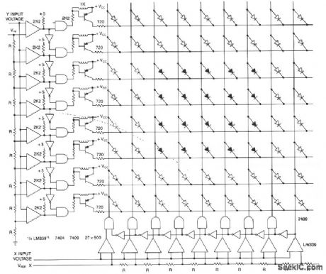
This matrix can show the values of two variables, for example, frequency and voltage. The display is a graph made from a matrix of LEDs. The LEDs on each axis are color coded, red for out of tolerance and green for in, forming a red band around the inner green rectangle. The two input voltages proportional to the functions being measured are presented to the two columns of comparators. The other comparator input is a reference voltage derived from resistor ladder R1 to RX. The output of each row of comparators is processed with an inverted and an AND gate to allow only one active output for any input value. The LED at the intersection of the active drives shows the relationship of the two inputs. The advantage of this display is the ease in reading, modification, and also its small size. All comparators are LM339 quads. (View)
View full Circuit Diagram | Comments | Reading(1959)
VOLTAGE_TUNED_WITH_10;1_FREQUENCY_RANGE
Published:2009/7/6 3:49:00 Author:May
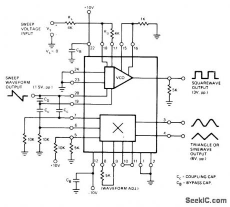
Exar XR-S200 PLL IC is connected to generate basic periodic square or sawtooth waveform. Multiplier section, used as linear differential amplifier, converts diffetential sawtooth input waveform to triangle wave. 5K pot connected between pins 8 and 9 rounds peaks of triangle to give low-distortion sine wave with less than 2% total harmonic distortion. Output frequency can be swept or frequency-moduiated by applying proper analog control input.For linear frequency modulation with less than 10% deviation, modulation is applied between pins 23 and 24. For larger deviations, negativegoing sweep voltage Vs is applied to pin 18 as shown. Digital control input pins 15 and 16 can be used for FSK applications; if this is not desired, pins are disabled by connecting to ground through current-limiting resistor.- Phase-Locked Loop Data Book, Exar Integrated Systems, Sunnyvale, CA, 1978, p 9-16. (View)
View full Circuit Diagram | Comments | Reading(560)
SIMPLE_CONTINUITY_TESTER_FOR_PCBs
Published:2009/7/6 3:49:00 Author:May
Circuit NotesThis tester is for tracing wiring on Printed Circuit Boards. Resistors below 50 ohms act as a short circuit; above 100 ohms as an open circuit. The circuit is a simple multivibrator switched on by transistor T3. The components in the base of T3 are D1, R1, R2, and the test resistance. With a 1.5 volt supply, there is insufftcient voltage to turn on a semiconductor connected to the test terminals. (View)
View full Circuit Diagram | Comments | Reading(1947)
HEADLIGHT_ALARM
Published:2009/7/6 3:48:00 Author:May
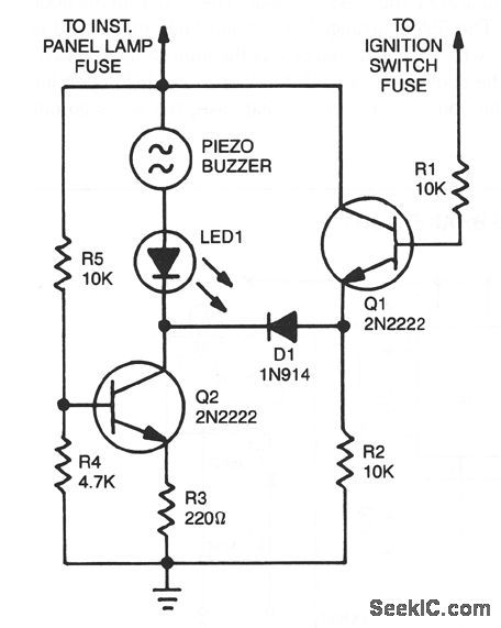
The base of Q1 is connected to the car's ignition circuit. One side of the piezoelectric buzzer is connected to the instrument-panel light fuse. When the headlights are off, no current reaches the buzzer, and therefore nothing happens. What happens when the headlights are on depends on the state of the ignition switch. When the ignition switch is on, transistors Q1 and Q2 are biased on, removing the buzzer and the LED from the circuit.When the ignition switch is turned off, but the headlight switch remains on; transistor Q1 is turned off, but transistor Q2 continues to be biased on. The result is that the voltage is sufficient to sound the buzzer loudly and light the LED. Turning off the headlight switch will end the commotion quickly. (View)
View full Circuit Diagram | Comments | Reading(0)
FLASHING_THIRD_BRAKE_LIGHT
Published:2009/7/6 3:46:00 Author:May
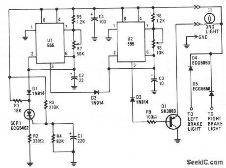
When power is first applied, three things happen: light-driving transistor Q1 is switched on due to a low output from U2 pin 3; timer U1 begins its tinting cycle, with the output, pin 3, becoming high, inhibiting U2's trigger, pin 2, via D2; and charge current begins to move through R3 and R4 to C1.
When U1's output becomes low, the inhibiting bias on U2 pin 2 is removed, so U2 begins to oscillate, flashing the third light via Q1, at a rate determined by R8, R6, and C3. That oscillation continues until the gate-threshold voltage of SCR1 is reached, causing it to fire and pull U1's trigger, pin 2,low.
With its trigger low, U1's output is forced high, disabling U2's triggering. With triggering inhibited, U2's output switches to a low state, which makes Q1 conduct, turning on I1 until the brakes are released.Of course, removing power from the circuit resets SCR1, but the rc network consisting of R4 and C1 will not discharge immediately and will trigger SCR1 earlier. So, frequent brake use means fewer flashes.
(View)
View full Circuit Diagram | Comments | Reading(1140)
POSITIVE_PEAK_DETECTOR
Published:2009/7/6 3:45:00 Author:May
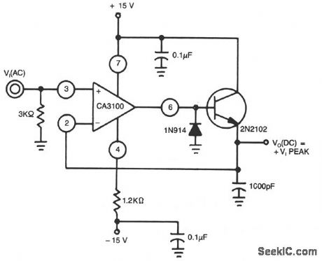
This peak detector uses a CA3100 BiMOS op amp as a wide-band noninverting amplifier to provide essentially constant gain for a wide range of input frequencies. The IN914 clips the negative half of VIN (R4)/(R3) (R5). A 500-μA load current is constant for all load values and the output reflects only positive input peaks. (View)
View full Circuit Diagram | Comments | Reading(0)
| Pages:1048/2234 At 2010411042104310441045104610471048104910501051105210531054105510561057105810591060Under 20 |
Circuit Categories
power supply circuit
Amplifier Circuit
Basic Circuit
LED and Light Circuit
Sensor Circuit
Signal Processing
Electrical Equipment Circuit
Control Circuit
Remote Control Circuit
A/D-D/A Converter Circuit
Audio Circuit
Measuring and Test Circuit
Communication Circuit
Computer-Related Circuit
555 Circuit
Automotive Circuit
Repairing Circuit