
Circuit Diagram
Index 1055
MEASURING_SCR_TURNOFF_TIME
Published:2009/7/23 21:48:00 Author:Jessie

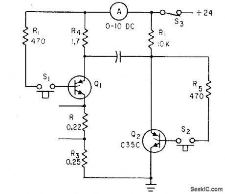
Q1 in parallel inverter circuit is triggered by dosing S1, to give 10 amp of test current. When S2 is closed after warmup, Q2 turns on, connects positively charged plate of C1 to cathode of Q1, and makes reverse current flow. If turnoff lime of Q1 is less than 12 microsec, it will remain turned off and ammeter reading will return to zero. If test rectifier fails to turn off, S3 should be opened immediately each drive monostable mvbr, with output to prevent overheating.-D. V. Jones, Turn-Off Circuits for Controlled Rectifiers, Electronics, 33:32, p 52-55.
(View)
View full Circuit Diagram | Comments | Reading(762)
FSK_SINE_SQUARE_TRIANGLE_GENERATOR
Published:2009/7/6 2:40:00 Author:May
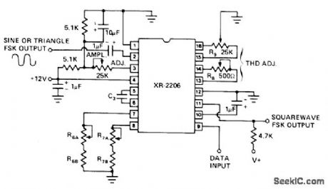
Exar XR-2206 modulator-demodulator (modem) is connected as function generator providing high-purity sinusoidal output along with triangle and square outputs, for FSK applications. Circuit has excellent frequency stability along with TTL and CMOS compatibility.Total harmonic distortion in 3 V P-P sine output is about 2.5% untrimmed, but can be trimmed to 0.5%. High-level data inputsignal selects frequency of 1/R6C3 Hz, while low-level input selects 1/R7C3 Hz. For optimum stability,R6 and R7 should be in range of 10K to 100K. Adiust R8 and R9 for minimum distortion.- Phase-Locked Loop Data Book, Exar Integrated Systems, Sunnyvale, CA, 1978, p 57-61. (View)
View full Circuit Diagram | Comments | Reading(7144)
MISSING_PULSE_DETECTOR
Published:2009/7/6 2:36:00 Author:May
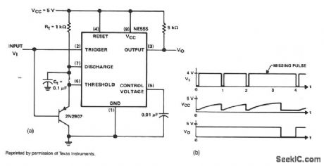
This circuit will detect a missing pulse or abnormally long spacing between consecutive pulses in a train of pulses. The timer is connected in the monostable mode. The time delay should be set slightly longer than the timing of the input pulses. The timing interval of the monostable circuit is continuously retriggered by the input pulse train, VI. The pulse spacing is less than the timing interval, which prevents VC from rising high enough to end the timing cycle. A longer pulse spacing, a missing pulse, or a termi-nated pulse train will permit the timing interval to be completed. This will generate an output pulse, VO as illustrated in Fig. 25-3b. The output remains high on pin 3 until a missing pulse is detected at which time the output decreases.
The NE555 monostable circuit should be running slightly slower, lower in frequency, than the frequency to be analyzed. Also, the input cannot be more than twice this free-running frequency or it would retrigger before the timeout and the output would remain in the low state continuously. The circuit oper-ates in the monostable mode at about 8 kHz, so pulse trains of 8 to 16 kHz can be observed. (View)
View full Circuit Diagram | Comments | Reading(0)
IMPROVED_CODAN
Published:2009/7/23 21:48:00 Author:Jessie
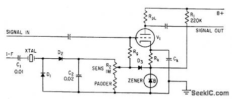
Applied to first audio tube of receiver. Tube is biased off by zener diode in cathode circuit, and keep alive current is supplied to zener from B+. Actuating codan, consisting of crystal, voltage-doubling rectifier, smoothing capacitor C2, and load, produces positive output only when signal is received from i-f. Crystal is at 1.1 center frequency. Audio is thus unblocked only when voltage of desired signal, as set by R2, is sufficient to overcome cutoff bias in cathode circuit.-R. L. Ives, Crystal Codans Give Accurate Receiver Tuning, Electronics, 33;22, p 113. (View)
View full Circuit Diagram | Comments | Reading(842)
SCALER_FOR_CB
Published:2009/7/6 2:35:00 Author:May


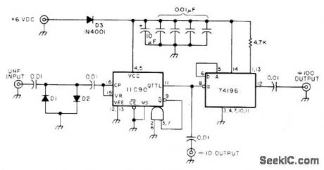
Low-cost prescaler for low-range frequency counter permits accurate monitoring of 450-MHz CB transceiver. Fairchild 11C90 decade counter gives division by 10 for counters covering up to 45 MHz. For lower-range counter, add 74196 TTL decade counter as shown to give total division by 100 for conversion to 4.5-MHz output. D1 and D2 should be fast-switching diodes such as 1N914 or 1N4148.Keep input signal under 1 V to avoid damaging 11C90. Will operate from 5-V supply or four D cells.-P. A. Stark, 500 MHz Scaler, 73 Magazine, Oct. 1976, p 62-63. (View)
View full Circuit Diagram | Comments | Reading(4584)
Basic_unity_gain_voltage_follower
Published:2009/7/23 21:48:00 Author:Jessie
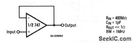
This circuit uses one-half of a 747 connected in the classic unity-gain voltage-follower configuration, where the input impedance is high and the output impedanceis low. (View)
View full Circuit Diagram | Comments | Reading(938)
Mitsubishi Pajero light off-road vehicles front and rear window wiper washing wiring circuit diagram
Published:2011/5/10 0:57:00 Author:Rebekka | Keyword: Mitsubishi Pajero, light off-road vehicles, wiper washing wiring
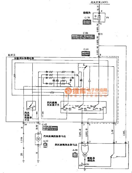
Mitsubishi Pajero light off-road vehicles front and rear window wiper washing wiring circuit diagram is shown as above. (View)
View full Circuit Diagram | Comments | Reading(2036)
Switching_time_tests
Published:2009/7/23 21:48:00 Author:Jessie
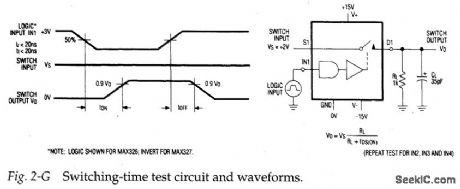
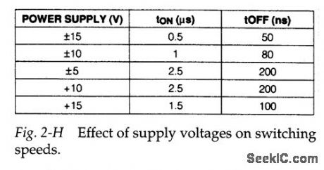
Figure 2-G shows a test circuit and waveforms for measuring switching time for the MAX326/27 .As a point of reference, tON should be between 500 and 1000 ns, with tOFF between 50 and 500 ns. Figure 2-H shows how switching speeds are affecter by supply voltages.
(View)
View full Circuit Diagram | Comments | Reading(740)
Basic_D_A_converter_configurations
Published:2009/7/23 21:47:00 Author:Jessie
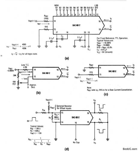
These circuits show various configurations for a DAC-6012 connected as a D/A converter for stand-alone operation. Figure 6-39A shows basic positive-reference operation. Figure 6-39B shows recommended full-scale adjustment circuit. Figure 6-39C shows basic negative-reference operation. Figure 6-39D shows pulsed-reference operation. (View)
View full Circuit Diagram | Comments | Reading(618)
Analog_multiplier_divider
Published:2009/7/23 21:47:00 Author:Jessie
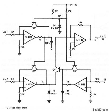
This circuit uses all four sections of a 4136 to form a circuit that both multiplies and divides (simultaneously if required). Virtually any pnp transistors can be used for Q1 through Q4, provided that the transistors are matched. The accuracy of the circuit multiplication and division depends on transistor matching. (View)
View full Circuit Diagram | Comments | Reading(977)
4O_1_SCALER_FOR_1200_MHz
Published:2009/7/6 2:33:00 Author:May
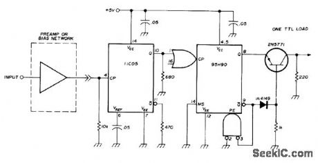
Uses Fairchild 11C05 divide-by 4 counter and 95H90 decade divider. Unused CP input is tied to ground. Transistor translates ECL level to TTL for driving one unit load. Operatesfrom single regulated power supply. Input may be AC or DC coupled so either input amplifier or simple bias network (also given in article) may be used. 10K resistor from pin 4 to ground eliminates noise triggering in middle frequency ranges.-D. Schmieskors, 1200-MHz Frequency Scalers, Ham Fladio, Feb.1975, p 38-40.
(View)
View full Circuit Diagram | Comments | Reading(916)
Off_channel_leakage_tests
Published:2009/7/23 21:44:00 Author:Jessie
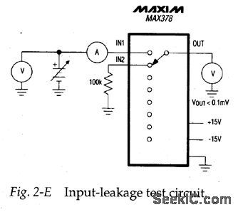
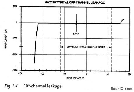
Figure 2-E is a test circuit for measuring off-channel input voltage versus the resulting input-leakage current. Figure 2-F shows typical test results. As shown, the input leakage during fault conditions is less than 20nA. The voltmeter at the out-put shows the effect of off-channel leakage on the selected channel. The effect with 100-kΩ, input resistors (less than 0.1 mV) is hardly noticeable.VOUT is limited by internal clamps to about 3 V less than the supply rails, and ranges between ±12 V with ±15-V supplies. VOUT collapses to 0 V when the power is off.
(View)
View full Circuit Diagram | Comments | Reading(916)
DIGITAL_FREQUENCY_DETECTOR
Published:2009/7/6 2:32:00 Author:May
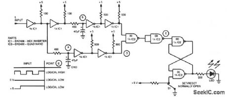
A simple inventer and NAND gate can be connected to yield a highly compact and reliable digital frequency detector. This circuit can detect frequencies up to 3 MHz with 50% duty cycles. When a frequency, fi, appears at the input, points A and B detect a logical high dc level. Thereupon point E increases the latch sets and the LED lights. If the input frequency is absent and if the voltage is either at a constant high or low level, points A and B will be complementary and point E will decrease. This will reset the latch and extinguish the LED. (View)
View full Circuit Diagram | Comments | Reading(2242)
2500_FREQUENCIES_WITH_SYNCHRONIZA_TION
Published:2009/7/6 2:32:00 Author:May
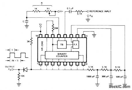
EXAR XR-2240 programmable timer/ counter containing 8-bit programmable binary counter and stable time-base oscillator can generate over 2500 discrete frequencies from single input reference frequency. Circuit simultaneously multiplies input frequency by factor M and divides by N + 1, where M and N are adjustable integer values. Output frequency Fo is equal to input frequency FR multiplied by M/(1 + N). M and N can be externally adjusted over broad range, with M between 1 and 10 and N between 1 and 255. Multiplication factor M is obtained by locking on harmonics of reference.Division factor N is determined by preprogrammed count in binary counter section, established by wiring appropriate pins 1-8 to output bus. Input reference is 3 V P-P pulse train with pulse duration ranging from 30% to 80% of time-base period T. R1 determines value of M. C is in range of 0.005 to 0.1 μF, and R is between 1K and1 megohm for maximum output frequency of about 200 kHz. With M = 5 and N = 2, 100-Hz clock synchronized to 60-Hz line frequency is obtained.- Timer Data Book, Exar Integrated Systems, Sunnyvale, GA, 1978, p 31-32. (View)
View full Circuit Diagram | Comments | Reading(1063)
Mitsubishi Pajero light off-road vehicle electric control rearview mirror and cigarette lighter principle circuit
Published:2011/5/10 0:57:00 Author:Rebekka | Keyword: Mitsubishi Pajero , light off-road vehicle, electric control rearview mirror , cigarette lighter
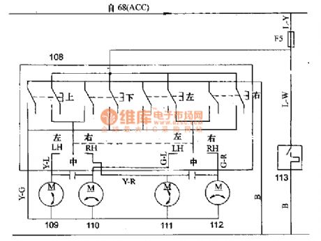
Mitsubishi Pajero(PAJERO) light off-road vehicle electric control rearview mirror and cigarette lighter principle circuit .
68 fire switch; 108 rear view mirror remote control switch; 109,110 left rear view mirror remote control motivation; 111,112 right rear view mirror remote control motor; 113 cigar lighter. (View)
View full Circuit Diagram | Comments | Reading(789)
INPUT_BUFFER_FOR_100_MHz_COUNTER
Published:2009/7/6 2:31:00 Author:May
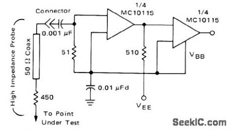
Can be used with 500-ohm probe for wide range of high-frequency input signal levels and waveforms, as part of frequency counter using standard emitter-coupled logic. Opamps used have 50-ohm input impedance. 450-ohm resistor in series with coax gives 10:1 attenuation factor (80 mV at amplifier input when measuring 800-mV ECL swing).-W. R. Blood, Jr., Measure Frequency and Propagation Delay with High Speed MECL Circuits, Motorola, Phoenix, AZ, 1972, AN-586, p 3. (View)
View full Circuit Diagram | Comments | Reading(991)
RAMP_GENERATOR_COMPARATOR
Published:2009/7/6 2:29:00 Author:May
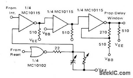
Developed for frequency counter using standard ECL components. One input to comparator is from integrator stage, and other is from ramp generator driven by reset signal from UJT oscillator.-W. R. Blood, Jr., Measure Frequency and Propagation Delay with High Speed MECL Circuit , Motorola, Phoenix, AZ, 1972, AN-586 p 3. (View)
View full Circuit Diagram | Comments | Reading(932)
DELAYED_EXTRA_BRAKE_LIGHT
Published:2009/7/6 2:26:00 Author:May
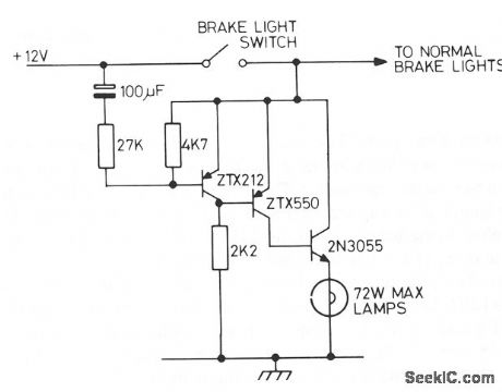
Operating the brake pedal of the car brings on the normal brake lights and then, after a delay, the extra lights are tumed on. A bimetal strip in series with the the lights would make them flash. (View)
View full Circuit Diagram | Comments | Reading(990)
500_MHz_WITH_100_Hz_RESOLUTION
Published:2009/7/6 2:25:00 Author:May
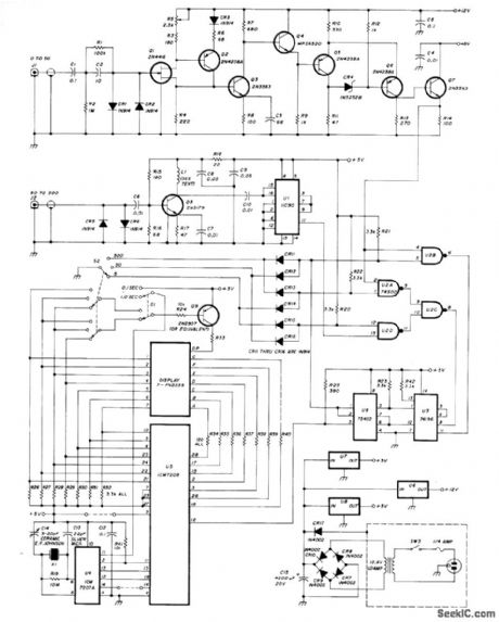
Circuit provides separate 0-50 MHz preamp Q1-Q7 and 50-500 MHz prescaler for Intersil IC M7207A 7-digit CMOS frequency counter. 500-MHz prescaler uses Fairchild 11C90 that drives TTL directly, with 2N5179 transistor as preamp. L1 and output capacitance of 2N5179 form low-Q resonant circuit. U3 is 50-MHz presealer for both preamps. Crystal frequency is 5.242880 MHz. 5-V regulators are MC7805, and 12-V regulator is MC7812. Article covers construction and adjustment.-J. H. Bordelon, Simple Front-Ends for a 500-MHz Frequency Counter, Ham Radio, Feb. 1978, p 30-33.
(View)
View full Circuit Diagram | Comments | Reading(5425)
Low_cost_supervisory_circuit_with_battery_backup_30_V_33_V
Published:2009/7/23 21:38:00 Author:Jessie
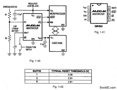
Figures 1-40 and 1-41 show a typical application circuit and pin configuration, respectively, for the MAXTO4T/S/R. The ICs are similar to that described for Figs.1-J through 1-M, but with generally lower cost, and for use with 3.0-V/3.3-V systems. The ICs have a 200-ms reset time delay, 50-μA quiescent current, 50-nA quiescent with battery backup, and a 1.25-V threshold detector for power-fail warning, low-battery detection, or for monitoring a supply other than 3.0 V or 3.3 V. The T, S, and R versions have different threshold levels, as shown in Fig. 1-42. MAXIM NEW RE[,EASES DATA Book, 1994, p 5-43. (View)
View full Circuit Diagram | Comments | Reading(814)
| Pages:1055/2234 At 2010411042104310441045104610471048104910501051105210531054105510561057105810591060Under 20 |
Circuit Categories
power supply circuit
Amplifier Circuit
Basic Circuit
LED and Light Circuit
Sensor Circuit
Signal Processing
Electrical Equipment Circuit
Control Circuit
Remote Control Circuit
A/D-D/A Converter Circuit
Audio Circuit
Measuring and Test Circuit
Communication Circuit
Computer-Related Circuit
555 Circuit
Automotive Circuit
Repairing Circuit