
Signal Processing
Index 73
BASIC_NE602_COLPITTS_CRYSTAL_OSCILLATOR
Published:2009/7/12 23:26:00 Author:May
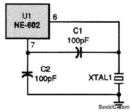
This basic Colpitts crystal oscillator will work with fundamental-mode crystals up to 20 MHz. (View)
View full Circuit Diagram | Comments | Reading(1450)
NE602_ADJUSTABLE_ORYSTAL_OSCILLATOR
Published:2009/7/12 23:25:00 Author:May
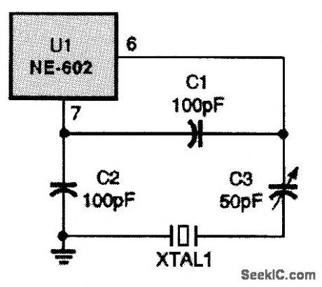
Here, a variable capacitor is added to the circuit to make it easier to obtain the desired frequency. (View)
View full Circuit Diagram | Comments | Reading(922)
NE602_THIRD_OVERTONE_CRYSTAL_OSCILLATOR
Published:2009/7/12 23:20:00 Author:May
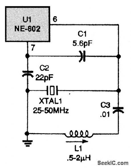
This overtone crystal oscillator uses thirdovertone crystals and will work from 25 to 50 MHz. (View)
View full Circuit Diagram | Comments | Reading(1219)
VOLTAGE_MONITOR
Published:2009/7/16 21:11:00 Author:Jessie
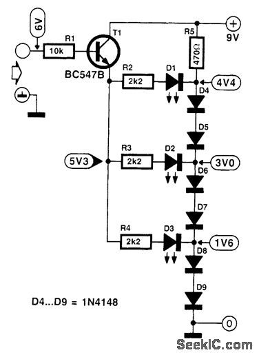
When voltages are measured, it is not always necessary to find the exact value. Often, it is sufficient to check whether a potential lies within a certain range of voltages. The present circuit indicates by means of three LEDs whether a voltage is greater than 4 V, 5.7 V, or 7.4V. The reference potential is provided by a series network of diodes D4 to D9. The LEDs are connected to various junctions in this network. The measurand is applied to the LEDs via emitter follower T1 and series resistors. Any one LED will light only if the input voltage exceeds the sum of the base-emitter junction of T1, the drop across the relevant series resistor, the LED voltage, and the drop across the diodes following the LED. (View)
View full Circuit Diagram | Comments | Reading(1)
PULSE_HEIGHT_DISCRIMI_NATOR
Published:2009/7/16 21:11:00 Author:Jessie
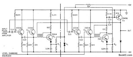
Selected pulses pass through timing gate Q7 (open for fixed time) to counter that registers average intensity of solar radiation falling in give wavelength band.-J. Ackroyd, Orbiting Spectrometer Plots Solar X-Rays, Electronics, 34:43, p 55-57. (View)
View full Circuit Diagram | Comments | Reading(815)
NE602_OVERTONE_ORYSTAL_OSCILLATOR
Published:2009/7/12 23:18:00 Author:May
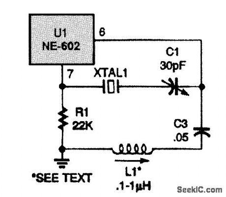
For higher frequencies, use an overtone crystal oscillator like the one shown here. The circuit is a Butler oscillator. The overtone crystal is connected between the oscillator emitter of the NE602 (pin 7) and a capacitive voltage divider that is connected between the oscillator base (pin 6) and ground. An inductor is also in the circuit (L1),and it must resonate with C1 to the overtone frequency of crystal XTAL1. The circuit can use either third- or fifth-overtone crystals up to about 80 Fig. 24-4 MHz. (View)
View full Circuit Diagram | Comments | Reading(2624)
PIERCE_ORYSTAL_OSCILLATOR
Published:2009/7/12 23:17:00 Author:May
View full Circuit Diagram | Comments | Reading(1056)
CMOS_CRYSTAL_OSCILLATOR
Published:2009/7/12 23:16:00 Author:May
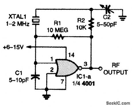
This single CMOS two-input NOR-gate crystal oscillator circuit has one major limitation: It lacks high-frequency performance. Otherwise, it is a solid performer. (View)
View full Circuit Diagram | Comments | Reading(0)
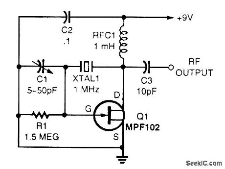
VERSATILE_WIDEBAND_ORYSTAL_OSCILLATOR
Published:2009/7/12 23:15:00 Author:May
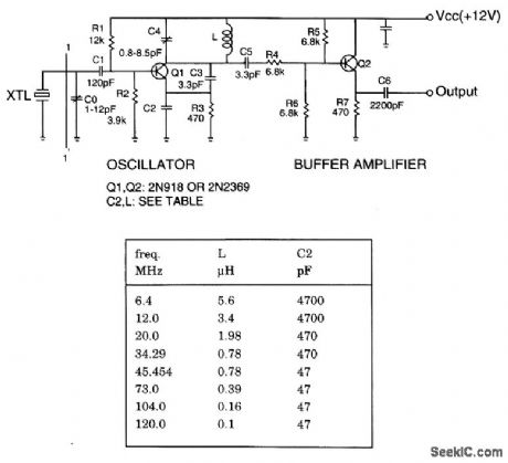
The crystal oscillator operates from 6 to 120 MHz by changing only C2 and L. The table lists component vaues for crystal oscillator at different frequencies. (View)
View full Circuit Diagram | Comments | Reading(1041)
005_cps_TO_10_KC_POSITIVE_PULSES
Published:2009/7/16 21:03:00 Author:Jessie
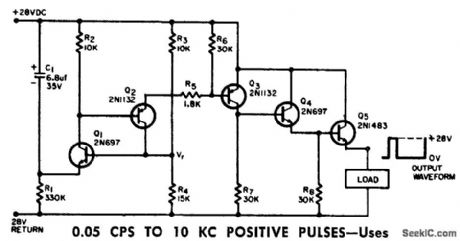
Uses two -transistor equivalent circuit for double-base diode, to give better relictbility and more uniform performance in recycling timers, indicator readouts, and switching regulators. With parameter values shown, frequency is about 1 cps and pulse width is 30 millisec.-G. B. Mahoney, Low-Frequency Pulse Generator, EEE, 12:6, p 63-64. (View)
View full Circuit Diagram | Comments | Reading(826)
VARIABLE_WIDTH_AND_VARIABLE_PRR
Published:2009/7/16 21:01:00 Author:Jessie
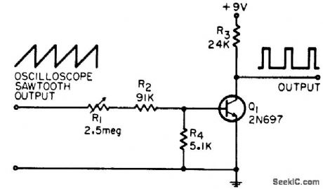
Gives wide range of control over pulse width and pulse repetition rate, while maintaining synchronization with oscillosope. Can be con strutted with banana plugs for sawtooth output jacks of scope.-R. G. Rakes, Simple Variable Width, PRR Pulse Generator, EEE, 13:11, p 45-46. (View)
View full Circuit Diagram | Comments | Reading(786)
LEVEL_DETECTOR
Published:2009/7/16 20:51:00 Author:Jessie
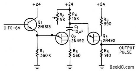
Provides constant-width pulses at fixed repetition rate whenever input signal exceeds predetermined level. Maximum current drawn from signal source is only 35 microamp.-J. G. Peddie, Two Unijunctions Form Low-Cost Level Detector, Electronics, 39:8, p 94. (View)
View full Circuit Diagram | Comments | Reading(1807)
SIMPLE_PULSE_STRETCHER
Published:2009/7/16 22:06:00 Author:Jessie
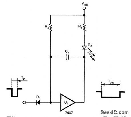
A single gate (open collector, noninverting) produces a simple one-shot to produce a pulse thatstretches equal to the pulse duration,plus the R1C1 time constant. R2 is a pull-up resistor to keep thegate's input high while waiting for a pulse. (View)
View full Circuit Diagram | Comments | Reading(1748)
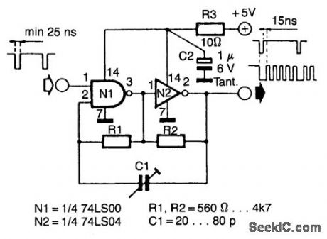
FAST_LOW_DUTY_CYCLE_PULSE_OSCILLATOR
Published:2009/7/16 22:05:00 Author:Jessie
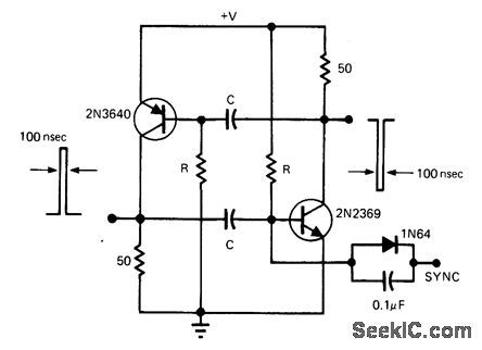
This simple and symmetrical free-running generator has a 50-Ω output impedance, a pulse width of 100 ns and complementary outputs that swing essentially from ground to the power-supply voltage. Moreover, it functions with a power supply range from < 1 to > 15 V and maintains a low voltage and temperature drift while consuming little power.
For oscillation to occur, each transistor must have a gain greater than unity. This restricts the value of R to a range of 1 kΩ to 1 MΩ, because the gain will be less than unity when the transistor is saturated or when beta is low as a result of small collector currents. The two RC timing networks do not have to match because the RC with the longest time constant will determine the frequency of oscillation. (View)
View full Circuit Diagram | Comments | Reading(949)
555_PULSE_GENERATOR
Published:2009/7/16 22:04:00 Author:Jessie
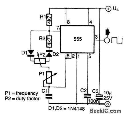
This approach to using a NEC555 timer uses two diodes to set the charge and discharge timer of capacitor, which gives the circuit a variable duty factor. (View)
View full Circuit Diagram | Comments | Reading(3555)
POSITIVE_PULSE_PULSE_STRETCHER
Published:2009/7/16 22:03:00 Author:Jessie
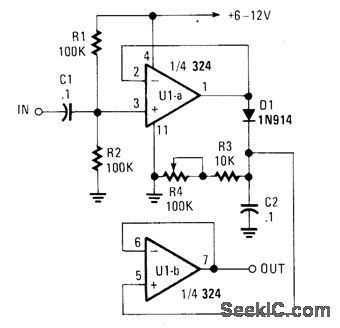
A simple pulse stretcher built with two sections of an op amp uses voltage follower U1A to drive D1 and C2. C2 charges to the peak value of pulse voltage. R3 and R4 determine the discharge time of C2 and therefore the pulse stretching. U1B acts as a voltage follower. Typically this circuit can stretch a pulse by a factor of 50. C2 can be charged to accommodate different pulse rates. (View)
View full Circuit Diagram | Comments | Reading(2899)
STABLE_START_STOP_OSCILLATOR
Published:2009/7/16 22:03:00 Author:Jessie
Oscillators that generate a predetermined number of pulses are often required in applications such as video work. This oscillator starts 13 ms after the control signal goes high and stops immediately when the input signal goes low. (View)
View full Circuit Diagram | Comments | Reading(958)
FREE_RUNNING_PULSE_GENERATOR
Published:2009/7/16 22:02:00 Author:Jessie
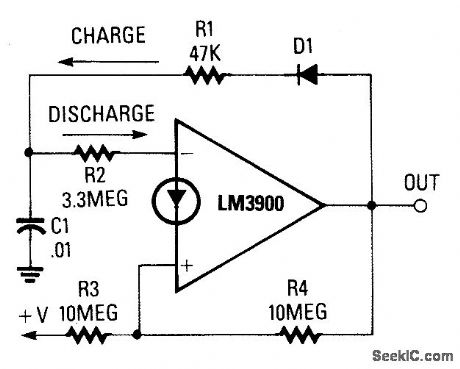
C1 alternately charges vla R1/D1 charges vla R2, which produces a dutyabout 1∶60. (View)
View full Circuit Diagram | Comments | Reading(617)
FLASH_MEMORY_PROGRAMMER
Published:2009/7/16 22:01:00 Author:Jessie
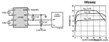
Generating 12V from a 5-V supply for flash memory usually requires a switching regulator and inductor to produce the necessary 30-rnA byte-wide flash. The LTC1262 reduces to just four small capacitors and no inductors the components required for this dc-to-dc conversion function, which generates 30 mA guaranteed output current from a 5-V ±5 percent supply. This surface-mount solution requires less than 0.2 in2. The LTC1262 features a charge-pump-gated oscillator/tripler architecture operating at 300 kHz. The gating of the oscillator regulates the output voltage at 12V.Operating supply current for the LTC1262 is 1 mA maximum, which drops just 10μA max when the device is shut down. Output voltage ramp-up is well behaved, with absolutely no overshoot. The LTC1262 is specified to operate with input voltages down to 4.75 V and up to 5.5V. (View)
View full Circuit Diagram | Comments | Reading(897)
TRANSISTOR_PULSE_GENERATOR
Published:2009/7/16 22:01:00 Author:Jessie
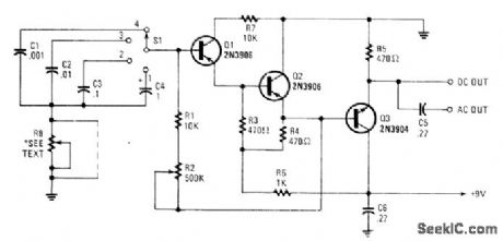
Seven-V narrow pulses from 2 Hz to 50 kHz are produced by this circuit. C1 through C4 provide frequency ranges in decode steps. R1 and R2 control the charging time of C1 through C4. R2 is a potentiometer used to set the frequency. R8 controls pulse width. Pulse width varies from 7 μs to 10 ms. Depending on the frequency, R8 can be deleted if it is not needed. (View)
View full Circuit Diagram | Comments | Reading(1256)
| Pages:73/195 At 206162636465666768697071727374757677787980Under 20 |
Circuit Categories
power supply circuit
Amplifier Circuit
Basic Circuit
LED and Light Circuit
Sensor Circuit
Signal Processing
Electrical Equipment Circuit
Control Circuit
Remote Control Circuit
A/D-D/A Converter Circuit
Audio Circuit
Measuring and Test Circuit
Communication Circuit
Computer-Related Circuit
555 Circuit
Automotive Circuit
Repairing Circuit