
Signal Processing
Index 63
LINEAR_VCO_1
Published:2009/7/14 4:44:00 Author:May
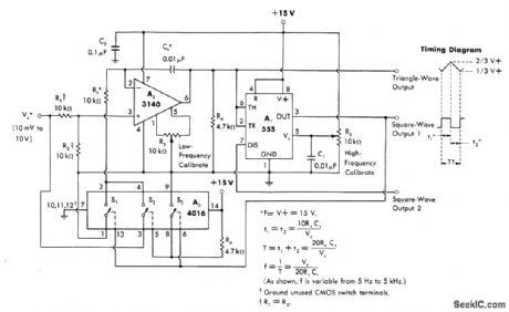
Operates over control-voltage range of +10 mV to +10 V to provide either square or triangle outputs from 5 Hz to 5 kHz, Can be used for instrumentation or electronic music applications.- W. G. Jung, IC Timer Cookbook, Howard W. Sams, Indianapolis, IN, 1977, p 174-179.
(View)
View full Circuit Diagram | Comments | Reading(1070)
FILM_TIMING_MARK_GENERATOR
Published:2009/7/14 4:33:00 Author:May
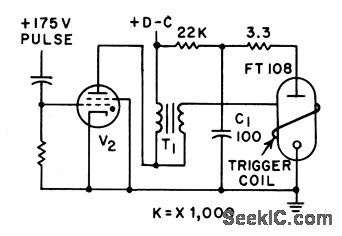
Instrumentation recorder for plasma studies uses discharge of capacitor at beginning of each plasma pinch discharge to trigger lash tube, light from which is chopped by glass disk driven at constant speed by synchronous motor.-J. J. Pearson, Instrumentation for Plasma Propulsion, Electronics, 33:24, p 66-69. (View)
View full Circuit Diagram | Comments | Reading(882)
LINEAR_VCO
Published:2009/7/14 4:40:00 Author:May
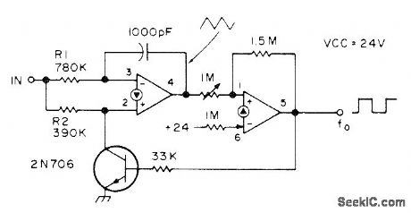
Two sections of LM3900 quad linear opamp provide linear response for inputs of 2-12 VDC, Circuit can be adjusted with 1-megohm pot so 4-V input produces 400-Hz square wave at output, 5 V gives 500 Hz, etc. First opamp is connected as integrator and second as Schmitt trigger. When Schmitt output is high, transistor is turned on and diverts current away from noninverting input so integrator output ramps down toward ground.-C. Sondgeroth, More PLL Magic, 73 Magazine, Aug. 1976, p 56-59. (View)
View full Circuit Diagram | Comments | Reading(0)
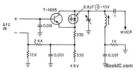
COLLECTOR_VOLTAGE_CONTROL_AFC_OSCILLATOR
Published:2009/7/15 3:36:00 Author:Jessie
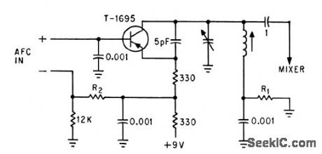
Afc input signal acts through series resistor to vary collector voltage of 40.Mc oscillator. Sensitivity is 2.5 Mc per V. Bias network adjustment is critical.-T. P. Prouty, Using Varactors to Extend Frequency-Control Range, Electronics, 36:45, p 48-49. (View)
View full Circuit Diagram | Comments | Reading(737)
VARACTOR_CONTROLLED_40_MC_OSCILLATOR_
Published:2009/7/15 3:35:00 Author:Jessie
Oscillator transistor also acts as a d-c amplifier between afc input and varactor diode to give electronic tuning over range of 11 Mc with sensitivity of 5.8 Mc per v.-T. P. Prouty, Using Varactors to Extend Frequency-Control Range, Electronics, 36:45, p 48-49. (View)
View full Circuit Diagram | Comments | Reading(813)
BALANCED_PARAMETRIC_DOUBLER
Published:2009/7/15 3:04:00 Author:Jessie


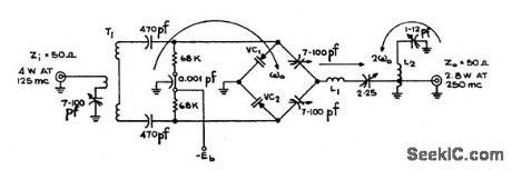
Handles twice the power of single-ended circuit using same varactor diode, while doubling 125-Mc input. Varactors VC are PSI type PC116.Efficiency is 70%. Transformer winding data is given in article.-R. D. Gromer, VHF Balanced Parametric Doubler, EEE, 11:8, p 30-31. (View)
View full Circuit Diagram | Comments | Reading(784)
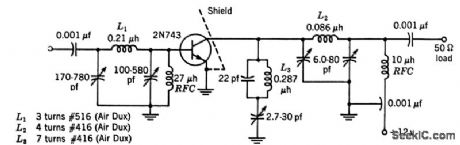
VHF_VARACTOR_QUADRUPLER
Published:2009/7/15 3:03:00 Author:Jessie
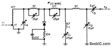
Supplies 160 Mc at up to 0.5 w. Output impedance is 50 ohms.-R. C. Wonson, Designing VHF Valactor Multipliers, FEE, 11;12, p 48-52. (View)
View full Circuit Diagram | Comments | Reading(721)
A_F_DOUBLER
Published:2009/7/15 3:03:00 Author:Jessie
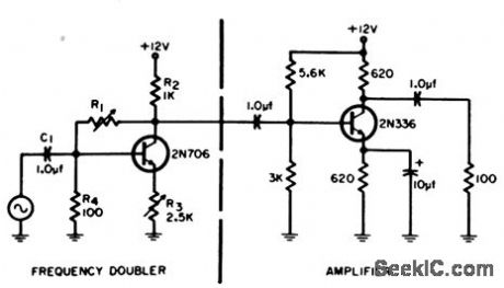
Frequency of sinusoidal signal is doubled with only one transistor, one coupling capacitor, and four resistors, by utilizing nonlinear characteristic of transistor for half-wave rectification. Purity of output waveform is adjusted with feedback control R1.-R. J. Miller, Jr., Audio Frequency Doubling Without Bulky filters, EEE, 12:12, p 57. (View)
View full Circuit Diagram | Comments | Reading(830)
50_MC_TO_100_MC_VARACTOR_DOUBLER
Published:2009/7/15 3:02:00 Author:Jessie
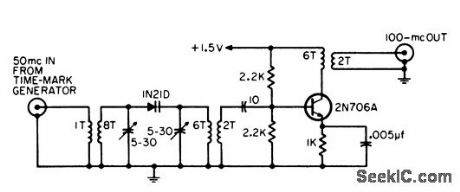
Used to extend usefulness of conventional time marker generator.-R. M. Zilberstein, Frequency Doublet and Amplifier, EEE, 12:12, p 57. (View)
View full Circuit Diagram | Comments | Reading(805)
21_MC_TO_42_MC_DOUBLER
Published:2009/7/15 3:01:00 Author:Jessie
Combination series-parallel trap in collector circuit provides 50 db rejection of fundamental in output that is tuned to second harmonic.-Texas Instruments Inc., Transistor Circuit Design, McGraw-Hill, N.Y., 1963, p 328. (View)
View full Circuit Diagram | Comments | Reading(826)
TRIPLER_DOUBLER_GIVES_700_1200_MC
Published:2009/7/15 2:59:00 Author:Jessie
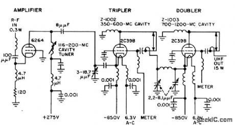
First stage is grounded-grid amplifier, with plate tuned by 1-turn coil and variable capacitor. Common-grid tripler and doublet are tuned with coaxial resonators. –A. E. Anderson and H. D. Hern, F-M Exciter For Sight or Scatter Systems,Electronics,31:11, p 148-151. (View)
View full Circuit Diagram | Comments | Reading(937)
DECADE_DRIVER_FOR_FREQUENCY_MULTIPLIER_
Published:2009/7/15 2:57:00 Author:Jessie
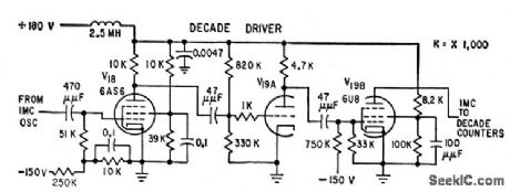
Input signal from frequency-multiplying oscillator is stepped up to 80 v peak-to-peak, with 1-microsec rise time, for accurate triggering of decade counter.-W. O. Brooks, Stepping up Frequency with Counter Circuits, Electronics, 32:29, p 60-62. (View)
View full Circuit Diagram | Comments | Reading(781)
RANDOM_FLASH_GENERATOR
Published:2009/7/14 4:32:00 Author:May
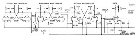
Multivibrators generate single pulse to drive flash tube at unspecified time of from 2 to 10 seconds after switch is closed.-P. Scott, Microflash and Pulse Stimulator Tests Human Response, Electronics, 34:27, p 48-51. (View)
View full Circuit Diagram | Comments | Reading(772)
SIMPLE_DOUBLER
Published:2009/7/15 2:57:00 Author:Jessie
Uses distributed R.C networks consisting of resistive and conductive layers on dielectric substrate, with d-c applied between electrodes at 65 v for doubling frequency of ceramic-dielectric 400-cps oscillator.-M. M. Perugini, Race to Reduce Capacitor Size, EEE, 10:7, p 61-64. (View)
View full Circuit Diagram | Comments | Reading(856)
50_150_MC_TRIPLER
Published:2009/7/15 2:56:00 Author:Jessie
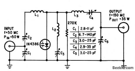
Charge-storage 1N4386 varactor triples frequency with power efficiency of 70% for input of 50 watts.-G. Schaffner, Charge Storage Vcractors Boost Harmonic Power, Electronics, 37:20, p 42-47. (View)
View full Circuit Diagram | Comments | Reading(917)
EMITIER_CURRENT_CONTROL_40_MC_AFC_OSCILLATOR
Published:2009/7/15 3:34:00 Author:Jessie
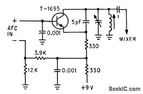
Error signal, usually derived from external discriminator, is applied in series with base bias network to give sensitivity of about 1.5 Mc per v and nearly straight voltage-frequency characteristic.-T. P. Prouty, Using Varactors to Extend Frequency-Control Range, Electronics,36:45, p 48-49. (View)
View full Circuit Diagram | Comments | Reading(819)
TRIGGERED_BLOCKING_OSCILATOR
Published:2009/7/14 4:20:00 Author:May
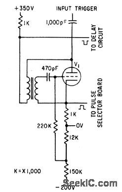
Gives pair of output pulses, with opposite polarity, for controlling timing and spacing of flashes.-P. Scott, Microflash and Pulse Stimulator Tests Human Optical Response, Electronics, 34:27, p 48-51. (View)
View full Circuit Diagram | Comments | Reading(871)
HYSTERESIS_AND_DELAY_OSCILLATOR
Published:2009/7/15 4:59:00 Author:Jessie
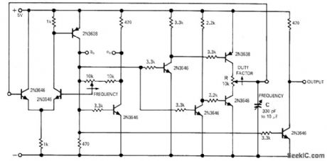
Separate noninteracting frequency and duty-factor controls permit construction of simple telemetry oscillators having inherently linear transfer function. Absolute synchronization of independent and dependent variables is obtainable with relatively simple pulse-generating circuits. Synchronization cannot be lost. Average value of threshold voltage is maintained constant. Adjustment of hysteresis gap width moves threshold voltage limits symmetrically about average value. Resistance portion of RC delay is switched from positive to negative voltage symmetrically also. Article covers circuit operation in detail.-W. H. Swain, True Digital Synchronizer Employs Hysteresis-and-Delay Element, EDN Magazine, Jan. 1, 1971, p 33-35. (View)
View full Circuit Diagram | Comments | Reading(978)
INDEPENDENT_ON_AND_OFF_PERIODS
Published:2009/7/15 4:55:00 Author:Jessie
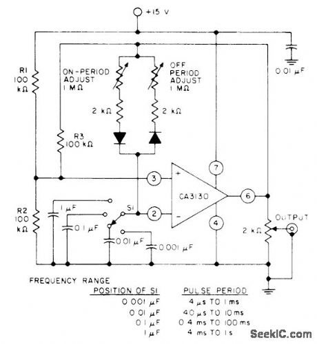
High input resistance of CA3130 opamp permits use of high RC ratios in timing circuits, to give pulse period range of 4 μs to 1 s with switch-selected capacitors.- Circuit Ideas for RCA Linear ICs, RCA Solid State Division, Somerville, NJ, 1977, p5. (View)
View full Circuit Diagram | Comments | Reading(822)
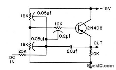
CURRENT_CONTROLLED_OSCILLATOR
Published:2009/7/14 4:06:00 Author:May
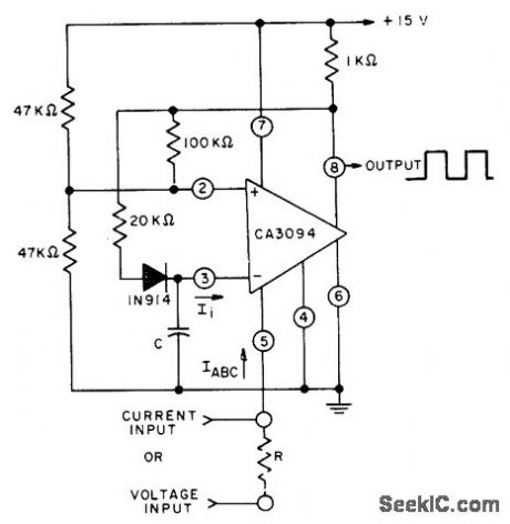
Makes use of proportional relationship between input current li and amplifier input bias current lABC of CA3094 programmable opamp. Linearity is within 1% over middle half of characteristic. Circuit can be used for voltage input if voltage is applied to pin 5 through appropriate dropping resistor R. Output is square wave. - Circuit Ideas for RCA Linear ICs, RCA Solid State Division, Somerville, NJ, 1977, p4. (View)
View full Circuit Diagram | Comments | Reading(1122)
| Pages:63/195 At 206162636465666768697071727374757677787980Under 20 |
Circuit Categories
power supply circuit
Amplifier Circuit
Basic Circuit
LED and Light Circuit
Sensor Circuit
Signal Processing
Electrical Equipment Circuit
Control Circuit
Remote Control Circuit
A/D-D/A Converter Circuit
Audio Circuit
Measuring and Test Circuit
Communication Circuit
Computer-Related Circuit
555 Circuit
Automotive Circuit
Repairing Circuit