
Signal Processing
Index 62
AVC_AND_VOX
Published:2009/7/14 7:59:00 Author:May
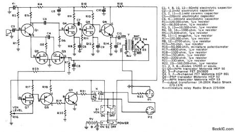
Voice-operated ON/OFF switch uses microphone to sense normal back-ground sound. Anything above background threshold preset by R16 energizes relay K for turning on recorder. Circuit provides about 2-s delay after subject stops talking, before releasing relay. Automatic volume control circuit keeps recorded signal essentially constant despite movements of loudspeaker toward or away from microphone.-G. Beard, Automatic Volume and VOX for Your Tape Recorder, Popular Science, Oct. 1973, p 134 and 136. (View)
View full Circuit Diagram | Comments | Reading(1513)
TWO_54_MC_OUTPUTS_FROM_3_MC
Published:2009/7/15 2:45:00 Author:Jessie
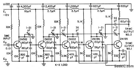
Uses three class AB common-emitter amplifiers.First two are triplets that multiply 3-Mc input to 27 Mc. Third doubles this to 54 Mc, and drives two parallel 54.Mc class AB output amplifiers providing 25 mw each.-J. W. Hamblen and J. B. Oakes, Instrumentation and Telemetry of Transit Navigational Satellites, Electronics, 34:32, p 148-153. (View)
View full Circuit Diagram | Comments | Reading(783)
SEQUENCE_GENERATOR
Published:2009/7/15 2:44:00 Author:Jessie
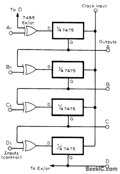
Uses gated shift register assembled from 7475 D-type latch, along with four EXCLUSIVE-OR gates. Clock pulse should be narrow to avoid race-around effects.-P. D, Maddison, Sequence Generator, Wireless World, Dec. 1977, p 80. (View)
View full Circuit Diagram | Comments | Reading(1445)
COMPLETE_40_MC_160_MC_QUADRUPLER
Published:2009/7/15 2:44:00 Author:Jessie
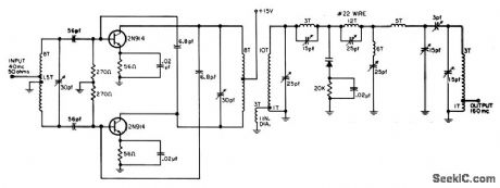
Transistor drive stage provides 10 db gain at 70% efficiency. Output power is 80 mw into 200 ohms. All coils are 1/2 inch diameter, using No.14 wire, unless otherwise specified.-R. C. Wonson, Designing VHF Varactor Multipliers, EEE, 11:12, p 48-52. (View)
View full Circuit Diagram | Comments | Reading(672)
60_420_CPS_FREQUENCY_SEPTUPLER
Published:2009/7/15 2:43:00 Author:Jessie
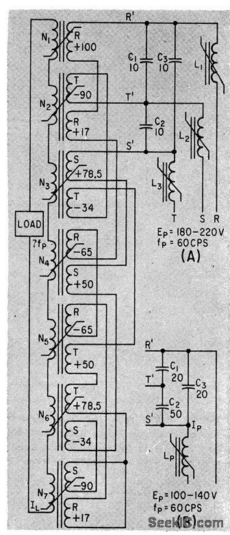
Seven saturable-core transformers, with series-star connected multiple primary windings and series-aiding secondaries, serve as static frequency multipliers delivering 40 w at 420 cps. Input may be three-phase (A) or single phase (B).-W. A. Geyger, Frequency Septupler Provides Stable 420-Cps Voltage, Electronics, 36:18, p 58-61., (View)
View full Circuit Diagram | Comments | Reading(775)
CONTROLLED_DURATION__PULSES
Published:2009/7/15 2:42:00 Author:Jessie
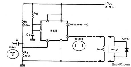
Economical Signetics IC provides output pulse currents up to 200mA at duration ranging from microseconds to many minutes depending on values used for R3 and C2. Input pulses may have duration under a microsecond, negative-going. With positive-going input pulses, output will be delayed until trailing edge occurs, Diode is required across output relay coil to suppress transients that might damage IC and cause automatic retriggering.-J. B. Dance, Simple Pulse Shaper or Relay Driver, Wireless World, Dec. 1973, p 605-606. (View)
View full Circuit Diagram | Comments | Reading(838)
FREQUENCY_MULTIPIJER
Published:2009/7/15 2:42:00 Author:Jessie
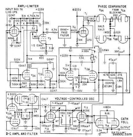
Phase comparator is combined with divider and digital feed. back loop to give highly accurate frequency multiplication over wide band of inputs. Multiplying factor is 1,000, but technique is adaptable to other values. Amplified output of phase comparator is used to regulate voltage-controlled oscillator.-W. O. Brooks, Stepping up Frequency with Counter Circuits, Electronics, 32:29, p 60-62. (View)
View full Circuit Diagram | Comments | Reading(820)
SELF_STARTING_DATA_GENERATOR
Published:2009/7/14 7:14:00 Author:May

Pseudo-random sequence built from shift resisters and exclusive-OR gates often are used to supply binary test data. If constructed from 100-kΩ ECL parts, such generators can run at up to 200 Mbits/s.Although an N-bit shift register can be connected to generate a sequence that repeats every 2N-1 bits,if it should start up in its all-zeros state, no output will be generated. What is needed is a counter to inject a 1 or to preload the shift register whenever N consecutive zeros are detected. The illustratesd circuit generates a 127-bit sequence. It provides a synchronization pulse once per repetition without using additional parts ,and it is guaranted to start. It uses the “wired-OR” property of ECL to generate a 1-bit period negative sync pulse when six zero are present (only five of these zeros are consecutive; a different set of N-1 bits might br needed if a longer shift register is used ). The sync pulse parallel-loads the shift register with the next state in the sequence. As a result, no seven-zero detector is needed to start the generator. (View)
View full Circuit Diagram | Comments | Reading(2002)
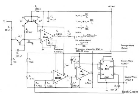
SWEEP_GENERATOR
Published:2009/7/14 7:09:00 Author:May
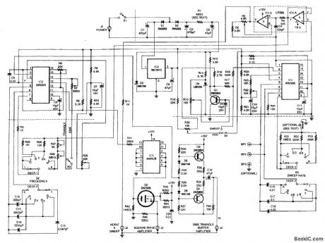
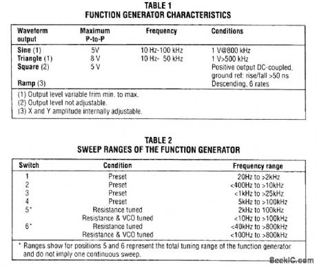
Both IC2 and IC4 are Exar XR2206 monolithic function generators; IC4 functions as a ramp generator, and IC2 functions as a generator of sine, triangular, and square waveforms. Dual operational-amplifier IC1 produces a scaled, level-shifted ramp output that is capable of deflecting an oscilloscope's horizontal sweep. This ensures that the sweep generator and the oscilloscope's sweep circuit are always properly synchronized. Any frequency of interest along the horizontal axis of an oscilloscope that is coupled to this function generator can be measured with an extemal frequency counter by manually tuning the function generator's VCO instead of sweeping it. The performance characteristics of the sweep/function generator are summarized in Table 1. The generator's sweep rate and frequency can be set by front-panel rotary six-position switches, SWEEP RATE switch S5 and FREQUENCY switch S2. The VCO control R30 manually tunes the VCO. Table 2 lists the sweep ranges of the function generator. Sweep ranges other than those covered in ranges 1 to 4 can be set up as required on positions 5 and 6. Selecting the VCO setting on the front-panel toggle switch S4 permits tuning any fixed frequency within the total frequency range of the instrument with both the FREQUENCY switch S2 and VCO control R30.
(View)
View full Circuit Diagram | Comments | Reading(0)
MULTIPLIER_GIVES_324_MC
Published:2009/7/15 2:39:00 Author:Jessie
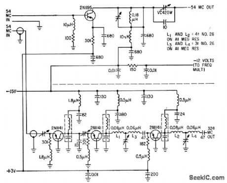
Two class B common-base stages (one tripler and one doubler) drive class AB common-base output amplifier to give 50 mw at 324 Mc from 54-Mc input. Upper section, a 54-Mc transmitter, is simply a single class AB common emitter that gives 200 mw output from 25-mw input.-J. W. Hamblen and J. B. Oakes, Instrumentation and Telemetry of Transit Navigational Satellites, Electronics, 34:32, p 148-153. (View)
View full Circuit Diagram | Comments | Reading(725)
ULTRA_FAST_MONOCYCLE_GENERATOR_
Published:2009/7/14 7:03:00 Author:May
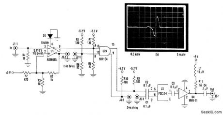
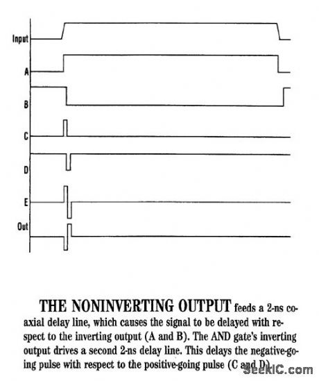
This circuit (Fig. 1a) can test an ultra-fast sample-and-hold amplifier, producing the monocycle shown (Fig.1b) when triggered with a TTL input pulse. The comparator (U1) squares up the input pulse and drives the AND gate (U2) with complementary outputs. The hysteresis resistors are chosen to provide reliable triggering despite the 50-Ω loading of the TTL input. The noninverting comparator output feeds a 2-ns coaxial delay line, causing the signal to be delayed with respect to the inverting output (Fig. 2). This forces the outputs of the AND gate to change state for a period of time equal to the delay. The inverting output of the AND gate drives a second 2-ns delay line, delaying the negative-going pulse, with respect to the positive-going pulse (Fig. 2). The power combiner (U3) sums the signals, producing a monocycle output. U4 amplifies the signal. Shorter pulses could be produced by shortening the delay lines and replacing U2 with an AND gate from a faster ECL family. (View)
View full Circuit Diagram | Comments | Reading(1670)
SIMPLE_FREQUENCY_GENERATOR_
Published:2009/7/14 7:00:00 Author:May
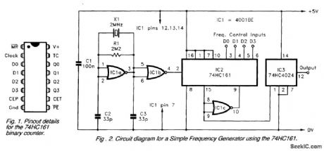
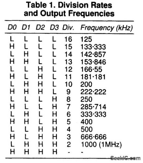
The circuit diagram for a simple frequency generator that uses a divide-by-N counter, based on a single 74HC161, is shown. Although IC1a and IC1b are NOR gates, in this circuit, they are used as inverters in a crystal clock generator. This provides an accurate 2-MHz output signal that is fed to the input of the divide-by-N circuit based on IC2 and IC1c. An inversion is needed between the comparator output and the negative active preset enable input, and this inversion is provided by IClc.Unfortunately, setting the division rate is more convoluted than simply writing the required value for N to the data inputs (D0 to D3). Table 1 shows the division rates and output frequencies for the 16 input codes for IC2. If the data inputs of IC2 are controlled via inverters, the division rate is one more than the value written to the port. Without a hardware inversion, a software inversion is required.This is actually quite easy, and it is just a matter of deducting the required division rate from 16 (e.g., for a division rate of 4, a value of 12 is written to IC2). Notice that the minimum division rate is 2, and that writing a value of 15 to IC2 will not give a division by 1. (View)
View full Circuit Diagram | Comments | Reading(3072)
150_450_MC_TRIPLER
Published:2009/7/15 2:37:00 Author:Jessie
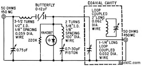
Charge-storage 1N4387 varactor gives 20 w at 450 Mc of 150-Mc input.-G. Schaffner, Charge Strorage Varactors Boost Power,Electronics,37:20, p42-47. (View)
View full Circuit Diagram | Comments | Reading(848)
PULSE_SHAPER_FOR_FREQUENCY_MULTIPLIER
Published:2009/7/15 2:36:00 Author:Jessie
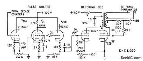
Combines clipping with cathode peaking to increase rise time to 1 microsec for 150.v pulses that drive blocking oscillator.-W. O. Brooks, Stepping up Frequency with Counter Circuits, Electronics, 32:29, p 60-62. (View)
View full Circuit Diagram | Comments | Reading(821)
PINK_NOISE_GENERATOR
Published:2009/7/14 7:15:00 Author:May
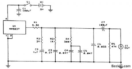
The MM5837 is a digital white-noise generator IC. It produces a clean white noise signal with only a power source. White noise appears at the output of this IC when power is applied. The white-noise signal is then fed through a -3-dB/octave filter to give pink noise. Because the minimum rolloff with a single-stage RC (resistor/capacitor) filter is -6 dB/octave (because of capacitive reactance), an unconventional filter design is needed. The technique involves cascading several stages of lag compensation so that the zeros of one stage partially cancel the poles of the next stage. The result is shown in the schematic of the figure. The response of this circuit is accurate to within ±1/2 dB. (View)
View full Circuit Diagram | Comments | Reading(0)
DIAL_TONE_GENERATOR
Published:2009/7/14 6:07:00 Author:May
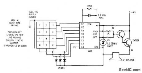
Simultaneous pairs of Touch-Tone frequencies used by telephone company are generated by adjustment-free circuit using Motorola Touch-Tone dialer with extenal 1-MHz crystal. Internal circuits of IC select proper division rates and convert outputs to synthesized sine waves of correct frequencies. Grounding one of row inputs by pressing key gives lower-frequency tone, while grounding one of column inputs gives higher-frequency tone. Special Touch-Tone keyboard provides this grounding action automatically when single key is pressed.-D. Lancaster, CMOS Cook-book, Howard W. Sams, Indianapolis, IN, 1977, p 239-240. (View)
View full Circuit Diagram | Comments | Reading(5272)
ERASE_BIAS_OSCILLATOR
Published:2009/7/14 5:09:00 Author:May
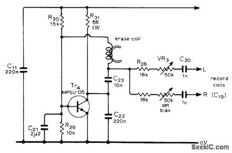
Used in high-quality stereo cassette deck operating from AC line or battery. Provides up to 33 VRMS at 50-kHz erase frequency, as required for completely erasing existing recording on tape when recording over it. Supply voltage should be in range of 12-14 V. Article gives all other circuits of cassette deck and describes operation in detail.- J. L. Linsley Hood, Low-Noise, Low-Cost Cassette Deck, Wireless World, Part 1-May 1976, p 36-40 (Part 2-June 1976, p 62-66; Part 3-Aug. 1976, p 55-56) (View)
View full Circuit Diagram | Comments | Reading(3909)
CONSTANT_CURRENT_GENERATOR
Published:2009/7/14 5:23:00 Author:May
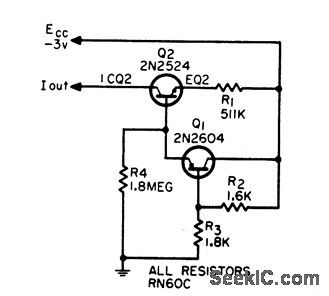
Provides 28 microamp, regulated within 0.75% over range of -20 to +60℃, to feed emitters low-level differential amplifier. Circuit compensates for base-emitter voltage change with temperature.-M. Wolpert and D. Spooner, Temperature Compensated Constant-Current Generator, EEE, 12:12, p 58. (View)
View full Circuit Diagram | Comments | Reading(1060)
EXPON_ENTIAL_VCO
Published:2009/7/14 4:58:00 Author:May
Can be driven with linear time base of voltage and used with logarithmic frequency display, as in frequency-response tests Useful range of circuit is four decades Values shown give timing-current range of 10 nA to 100 μA, yielding frequency range of 1 Hz to 10 kHz. Input voltage range of 60 mV per decade is obtained from voltage divider R1-R2 to allow higher and more practical value for actual input voltage to circuit. –W. G. Jung, IC Timer Cookbook, Howard W. Sams, Indianapolis, IN, 1977, p 174-179. (View)
View full Circuit Diagram | Comments | Reading(1191)
1_kHz_VCO
Published:2009/7/14 4:56:00 Author:May
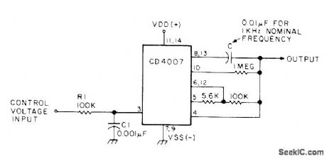
Changes in control voltage input are used to vary nominal 1-kHz output of CD4007 CMOS voltage-controlled oscillator proportionately. Values of R and C can be changed to obtain other nominal frequencies.-W. J. Prudhomme, CM0S Oscillators, 73 Magazine, July 1977, p 60-63.
(View)
View full Circuit Diagram | Comments | Reading(2632)
| Pages:62/195 At 206162636465666768697071727374757677787980Under 20 |
Circuit Categories
power supply circuit
Amplifier Circuit
Basic Circuit
LED and Light Circuit
Sensor Circuit
Signal Processing
Electrical Equipment Circuit
Control Circuit
Remote Control Circuit
A/D-D/A Converter Circuit
Audio Circuit
Measuring and Test Circuit
Communication Circuit
Computer-Related Circuit
555 Circuit
Automotive Circuit
Repairing Circuit